
Arduino Nano 33 IoT - BTS7960 Motor Driver
Say you have a 12V DC water pump for a garden bed or an aquarium, and you want to choose how strong the flow is. This tutorial instructs you how to use Arduino Nano 33 IoT and a BTS7960 motor driver module for this kind of job: the board sends a small PWM signal, and the BTS7960 turns it into real power for the motor. Later, the Wi-Fi of the Nano 33 IoT can bring that speed control to your phone. In detail, we will learn:
- Which job the two BTS7960B chips do, and where each wire of the 2 x 4 header goes on the Nano 33 IoT
- Why the VCC pin takes 5V from the +5V pin of the board, while the 12V adapter feeds only the B+ and B- terminals
- How to write a sketch in six steps: ramp up, full speed, ramp down, brake, half-speed reverse and coast
We suggest:
- Taking the Arduino Nano 33 IoT - DRV8833 DC Motor Driver tutorial when your motors are small. That tiny driver runs two of them from 2.7V to 10.8V.
- Picking the Arduino Nano 33 IoT - MOSFET Module tutorial when the pump only ever needs to turn one way.
Hardware Preparation
Or you can buy the following kits:
| 1 | × | DIYables Sensor Kit (18 sensors/displays) |
Additionally, some of these links are for products from our own brand, DIYables .
Overview of the BTS7960 Motor Driver and Its Pinout
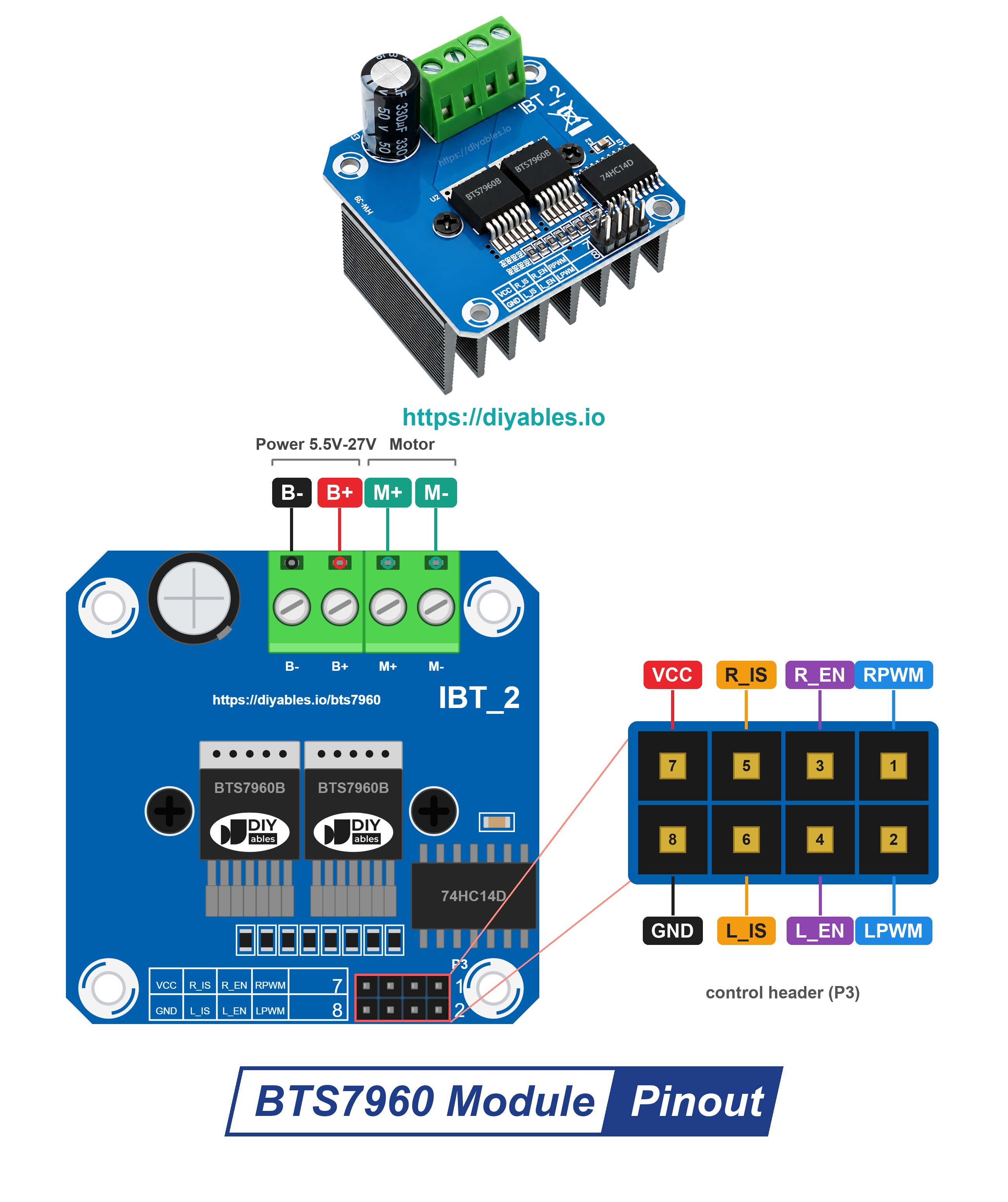
Shops also list this same board under the names IBT-2 and HW-039. Two Infineon BTS7960B chips sit on top of the board, and a big heat sink under the board keeps them cool. One chip alone is a half-bridge; the pair makes a full H-bridge. That is why the module can spin one brushed DC motor both ways, with PWM for the speed. Next to small drivers like the L298N or the DRV8833, it is the heavyweight: think big gear motors, wiper motors, winches, scooters and strong robot bases.
| BTS7960 Motor Driver Module | |
|---|---|
| Driver chips | Infineon BTS7960B, two of them (a half-bridge each) |
| Motor count | one brushed DC motor, forward or backward |
| Motor supply on B+ / B- | 5.5V to 27V DC, fits 6V, 12V or 24V motors |
| Current | up to 43A (the current-limit level, a peak value) |
| Highest PWM frequency | 25 kHz |
| Input buffer | 74HC14 chip, fed by the VCC pin |
| Safety features | current limiting and over-temperature protection |
The control side is a 2 x 4 male header. The top row holds VCC, R_IS, R_EN and RPWM. The bottom row holds GND, L_IS, L_EN and LPWM, so each "R" pin sits right above its "L" twin. Here is what each pin does:
- RPWM pin: must be connected to a PWM pin of the Arduino Nano 33 IoT. Pulses here spin the motor forward.
- LPWM pin: must be connected to a second PWM pin. Pulses here spin the motor backward.
- R_EN pin: must be connected to a digital pin. A HIGH level wakes up the right half-bridge.
- L_EN pin: must be connected to a digital pin. A HIGH level wakes up the left half-bridge.
- R_IS, L_IS pins: these report the current and any fault. This project ignores them, so leave them free.
- VCC pin: must be connected to the +5V pin of the Arduino Nano 33 IoT. It feeds just the 74HC14 buffer and the power LED; the motor takes nothing from it.
- GND pin: must be connected to a GND pin of the Arduino Nano 33 IoT.
- B+ and B- screw terminals: the motor power comes in here, plus on B+, minus on B-.
- M+ and M- screw terminals: the motor's own two leads go here.
※ NOTE THAT:
The silkscreen shortens R_IS / L_IS to "R_S" / "L_S". Other sellers of this IBT-2 style board may print the labels in a slightly different way. Go by the text on your own module, not by the position of the pin.
How the BTS7960 Turns the Motor
Think of each BTS7960B chip as a very fast switch for one motor wire: it can tie that wire to B+ or to B-. When one chip feeds its wire from B+ and the other chip ties its wire to B-, current runs through the motor one way. Swap the jobs of the two chips, and the current, and the motor, go the other way. The PWM signal flicks the B+ side on and off very quickly. The longer it stays on in each cycle (the duty cycle), the faster the motor spins.
As long as D12 and D11 hold R_EN and L_EN HIGH, the result depends only on the two PWM pins:
| RPWM (D9) | LPWM (D10) | Result |
|---|---|---|
| duty 0 to 255 | held at 0 | spins forward; more duty, more speed |
| held at 0 | duty 0 to 255 | spins backward; more duty, more speed |
| held at 0 | held at 0 | brake - M+ and M- are linked to each other, and the motor halts in a moment |
Drive R_EN and L_EN LOW, and both half-bridges switch off. This is "coast": the motor gets no power and rolls to a stop on its own, more slowly than with the brake.
At any moment, RPWM or LPWM (or both) must sit at 0. PWM on the two of them together is never allowed.
Powering the Module From a 3.3V Board
The BTS7960 module has two power sides. Keep them apart:
- Logic side: the VCC pin goes to the +5V pin. VCC only runs the buffer chip, and the module maker calls for 5V there. The control inputs are fine with 3.3V signals, so the pins of the Arduino Nano 33 IoT drive them without any help. (On this board, the +5V pin is VUSB. It gives 5V only after you close the VUSB solder jumper on the bottom of the board, and only while the board runs on USB power.)
- Motor side: the 12V adapter plugs into a DC power jack, and two wires run from the jack to the module: plus to B+, minus to B-. Never connect B+ to any pin of the Arduino Nano 33 IoT.
- Ground: on the module, the header GND is wired to B-. A single wire from a GND pin of the board to the GND pin of the header is enough: the board and the 12V adapter now share one ground.
Nothing is wired to R_IS or L_IS, so no signal travels from the module back to the board. The four control inputs only have pull-down resistors, so the 5V on VCC does not reach the board's pins. Nothing from the 12V side can reach the 3.3V pins this way.
What about the 43A? The chips start to limit the current at that point, so think of it as a peak, not a value for long runs. A motor or pump that runs for minutes or hours should draw far less. For long runs, how well the heat sink gets rid of heat sets the real limit. Also pick a 12V adapter rated for more amps than the motor draws.
Wiring Diagram
Only six jumper wires go to the Arduino Nano 33 IoT: four control lines, +5V and GND. The motor and the 12V adapter connect to the big screw terminals of the module, never to the board.
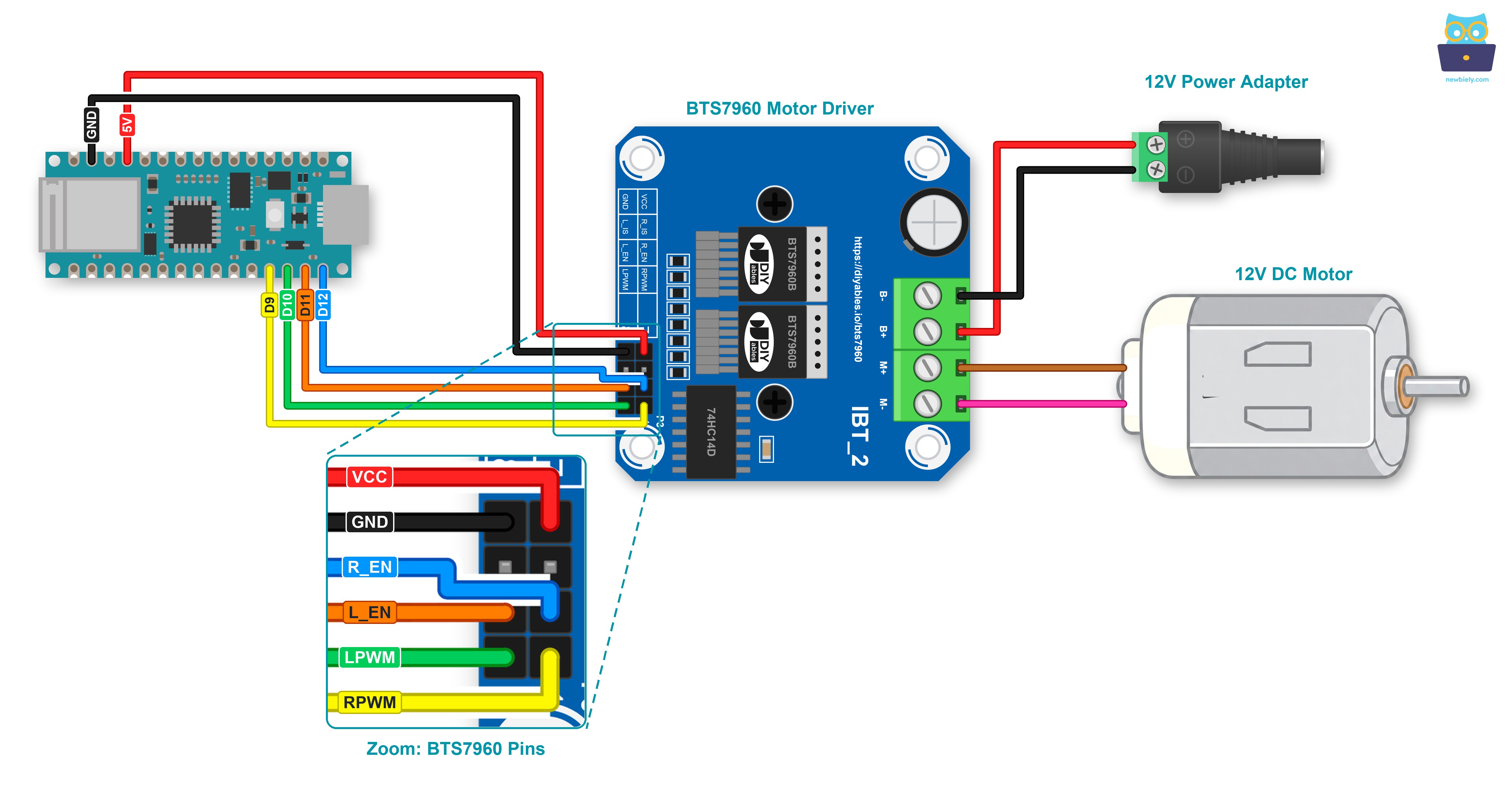
This image is created using Fritzing. Click to enlarge image
| BTS7960 Module | Arduino Nano 33 IoT / 12V Side |
|---|---|
| RPWM | D9 |
| LPWM | D10 |
| R_EN | D12 |
| L_EN | D11 |
| VCC | +5V (close the VUSB jumper first) |
| GND | GND |
| R_IS, L_IS | leave free |
| B+ | DC power jack, plus (+) terminal |
| B- | DC power jack, minus (-) terminal |
| M+, M- | motor leads (12V DC motor or 12V pump) |
A screw terminal keeps each wire tight, even when the board shakes. To do that, mount the Arduino Nano 33 IoT on a Screw Terminal Expansion Board for Arduino Nano. Below is the wiring diagram with the screw terminal board.
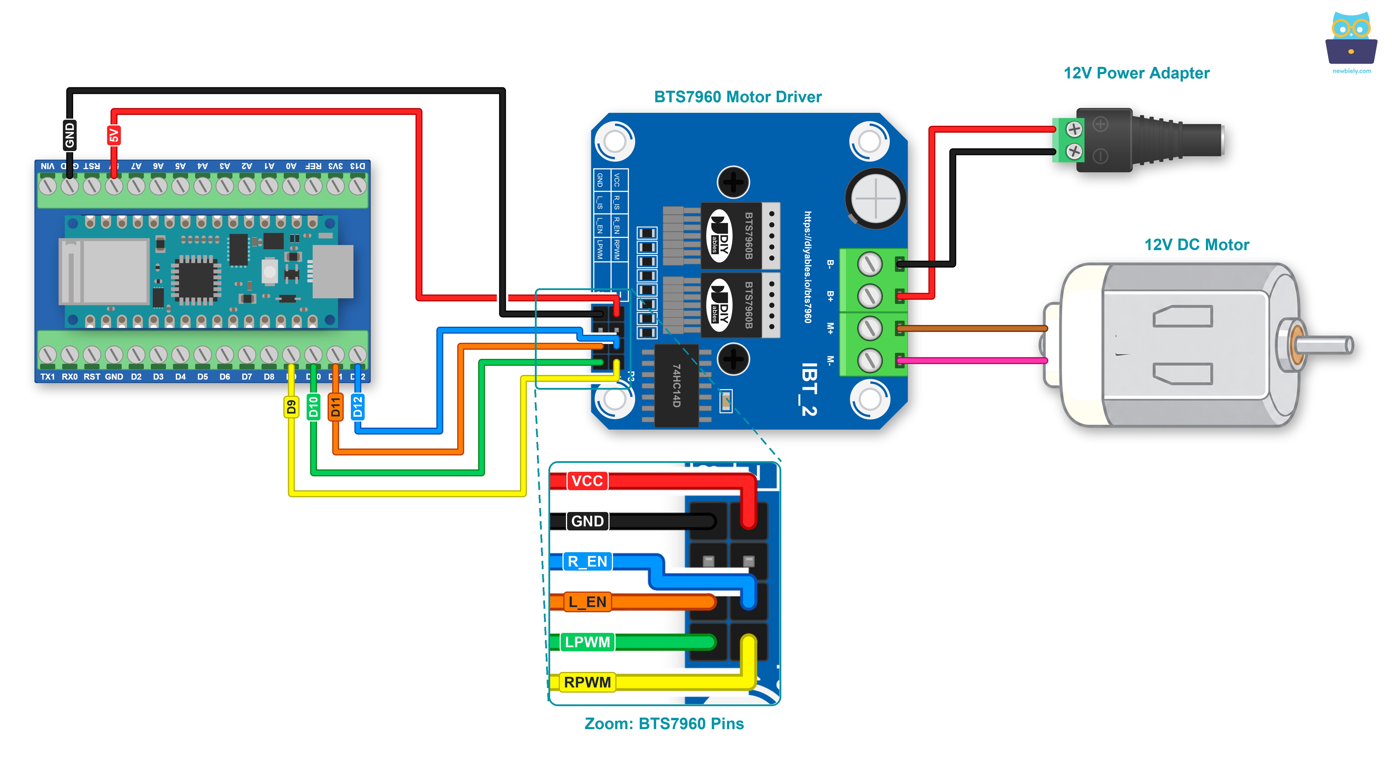
This image is created using Fritzing. Click to enlarge image
※ NOTE THAT:
Finish all the wiring first, and plug in the 12V adapter last. Before you plug it in, check that plus goes to B+ and minus goes to B-. Plus and minus the wrong way round can ruin the module.
How To Program For BTS7960 Motor Driver
No library is needed. The module only needs two kinds of signals: PWM from analogWrite() and HIGH / LOW from digitalWrite().
- The first step is to give a name to each Arduino Nano 33 IoT pin that goes to the control header:
- In setup(), make all four pins outputs. Hold both PWM pins at 0, and only then switch the driver on:
- To run forward, put 0 on LPWM and the speed (0 to 255) on RPWM:
- To run in reverse, it is the other way round:
- A brake is simply 0 on RPWM and on LPWM, with R_EN and L_EN left HIGH. For a coast, the enable pins go LOW as well, and they must be HIGH again before the motor can move once more.
※ NOTE THAT:
On the Arduino Nano 33 IoT, a pin that has been used with analogWrite() no longer listens to digitalWrite(). This wiring avoids the problem: D9 and D10 only ever get analogWrite(), while D12 and D11 only ever get digitalWrite().
Arduino Nano 33 IoT Code for BTS7960 Motor Driver
The sketch below wraps those lines into small helper functions: motorForward(), motorReverse(), motorBrake() and motorCoast(). Then it runs one round after another, and each round has six steps:
- Forward, with the speed rising from 0 to 255
- Full speed forward for 2 seconds
- Forward, with the speed falling back to 0
- Brake for 1 second
- Reverse at about half speed (128) for 2 seconds
- Coast for 2 seconds (driver off), then the driver is switched on again
Each step prints one line, with its number, to the Serial Monitor.
Detailed Instructions
First time with the Arduino Nano 33 IoT? Then set it up in the Arduino IDE with the Getting Started with Arduino Nano 33 IoT tutorial before you go on.
- Close the VUSB solder jumper on the bottom of the board, so the +5V pin gives 5V to VCC.
- Wire the components as shown in the diagram. The 12V adapter stays unplugged until the upload is done.
- Connect the Arduino Nano 33 IoT board to your computer using a USB cable.
- Open Arduino IDE on your computer.
- Select the Arduino Nano 33 IoT board and its COM port.
- Copy the code above and paste it into the Arduino IDE.
- Click the Upload button and wait for the upload to finish.
- Now connect the 12V adapter to the wall socket, so the motor side gets its power.
- Open the Serial Monitor, set it to 9600 baud, and keep your eyes on the motor shaft. It speeds up, runs at full speed, slows down, stops hard, turns the other way at half speed, and then rolls to a stop.
Does the motor turn the wrong way in step 1? Pull out the 12V adapter, then exchange the two motor leads on M+ and M-. The code stays the same.
At low speed, you may hear the motor hum or whine. This is normal: the default PWM frequency of the board is below 1 kHz, a sound you can hear.
Running a pump instead of a motor? Most pumps are made to turn in one direction only. Keep the forward steps, and remove the reverse step from the loop.
Additional Knowledge
BTS7960, L298N or DRV8833?
This board already has tutorials for the DRV8833 (also used in Arduino Nano 33 IoT - DC Motor) and the BTS7960 on this page. Here is how they compare with the older L298N:
| BTS7960 | L298N | DRV8833 | |
|---|---|---|---|
| How much current | up to 43A (peak) | about 2A per motor | about 1.5A per motor (2A peak) |
| Voltage drop in the driver | very little | about 2V | very little |
| How many motors | one | two | two |
It is evident that the BTS7960 is the one to choose when a single motor needs a lot of current. For two small motors, the DRV8833 is smaller and simpler.
Project Ideas
The Wi-Fi of the Arduino Nano 33 IoT and the strength of the BTS7960 work well together:
- A garden watering pump whose flow you set from your phone, slow for seedlings and strong for a big bed
- An aquarium pump that runs gently at night and at full flow during the day
- A pump that speeds up as the soil gets drier, with the reading from the Arduino Nano 33 IoT - Soil Moisture Sensor tutorial
- A small electric winch or a heavy robot base, where the motor needs both directions and a firm brake