
ESP32 S3 UNO - BTS7960 Motor Driver
Picture a robot that rolls on rubber tracks, like a small tank. Each track is pulled by a 12V gear motor, and the base is heavy with batteries. When it turns on the spot, the tracks drag sideways over the floor, and each motor asks for many amps, more than a hobby driver is made for. This is a job for the BTS7960. On this page, the ESP32 S3 Uno sends it four control signals and drives one such motor: faster, slower, backward, with a hard stop and with a soft one.
The route through this page:
- Find out what the RPWM, LPWM, R_EN and L_EN pins do, and why VCC goes to 5V on this 3.3V board
- Connect six jumper wires to D9, D10, D11, D12, 5V and GND, then the motor and the 12V adapter to the screw terminal
- Upload a sketch that ramps the motor up and down, brakes, backs up at half speed and then coasts
- See how a brake and a coast feel different, which matters when a heavy base must stop
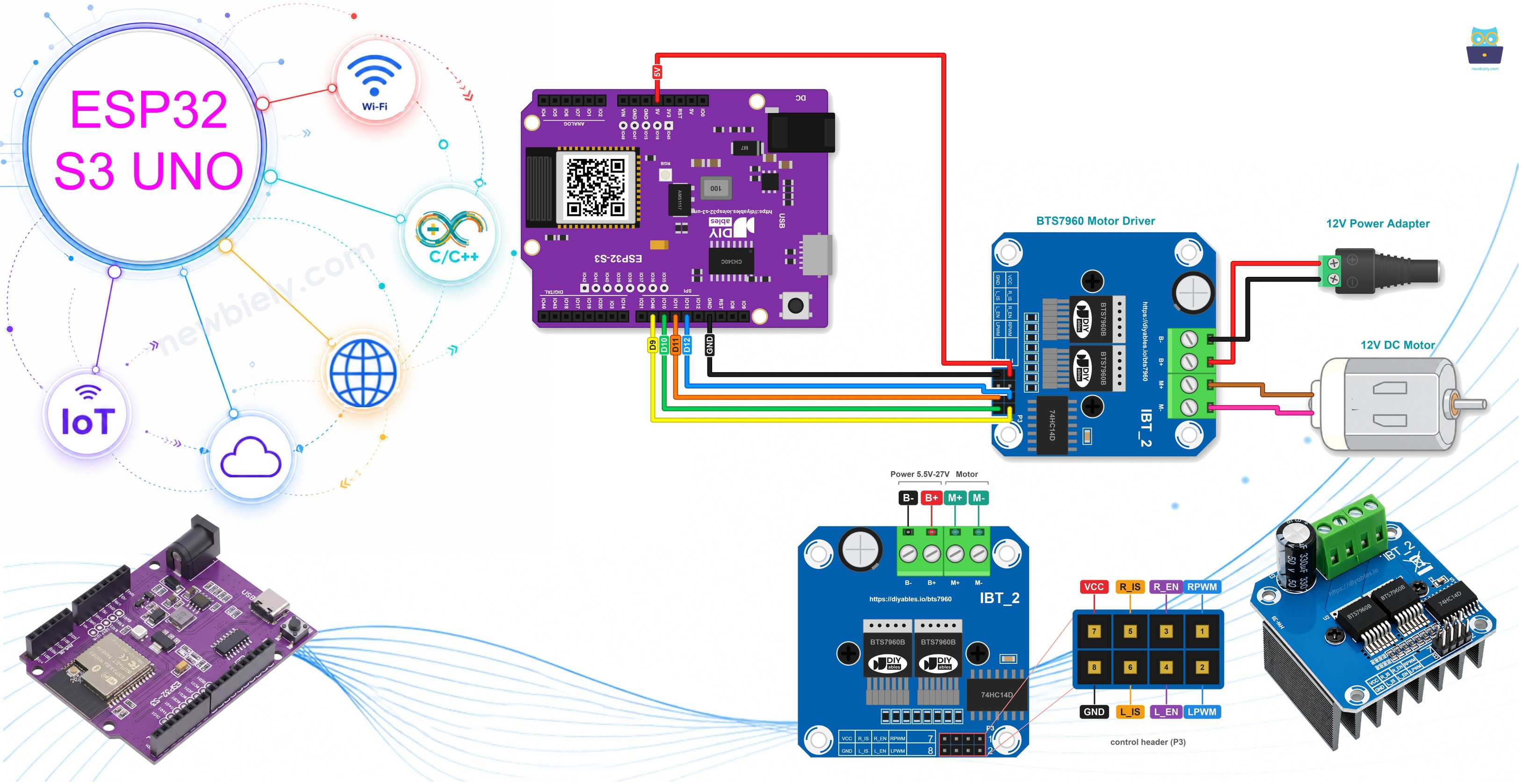
Nothing comes from the Library Manager this time. Two built-in functions do all the work: analogWrite() sets the speed, and digitalWrite() switches the driver on and off.
Hardware Preparation
Or you can buy the following kits:
| 1 | × | DIYables Sensor Kit (18 sensors/displays) |
Additionally, some of these links are for products from our own brand, DIYables .
Overview of BTS7960 Motor Driver
The DIYables BTS7960 43A Motor Driver Module is a large board with a big metal heat sink. Many shops sell the same design as "IBT-2" or "HW-039". Its power parts are two Infineon BTS7960B chips. Each chip is a half-bridge, and the two of them make one full H-bridge. So one board runs one brushed DC motor, in both directions, with PWM speed control. You can see it as the big brother of small drivers like the L298N and the DRV8833. It is made for large gear motors, wiper motors, winches, scooters, wheelchair motors and heavy robots.
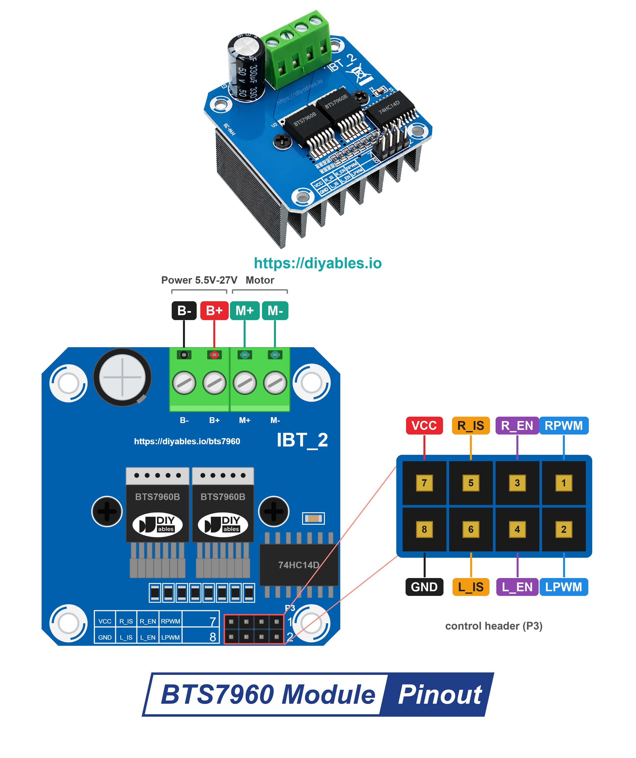
The board has two sides. The small 2 x 4 pin header is the control side, for the ESP32 S3 Uno. The screw terminal is the power side, for the 12V adapter and the motor. On the header, the pins come in pairs: every "R" pin in one row has its "L" partner right across from it in the other row.
- RPWM (pin 1): PWM signal for the right half-bridge (forward). Pulses here turn the motor forward. Goes to D9 (GPIO46).
- LPWM (pin 2): PWM signal for the left half-bridge (reverse). Pulses here turn the motor in reverse. Goes to D10 (GPIO10).
- R_EN (pin 3): switches the right half-bridge on when it is HIGH. Goes to D12 (GPIO13).
- L_EN (pin 4): switches the left half-bridge on when it is HIGH. Goes to D11 (GPIO11).
- R_IS (pin 5) and L_IS (pin 6): current-sense and fault outputs. On the silkscreen they read "R_S" and "L_S". This page does not use them, so they stay free.
- VCC (pin 7): power for the 74HC14 buffer chip and the power LED only. The motor never takes power from it. Goes to 5V.
- GND (pin 8): logic ground. The board joins it to B-. Goes to GND.
- B+ and B-: the motor supply, + and - of the 12V adapter.
- M+ and M-: the two wires of the DC motor.
| DIYables BTS7960 43A Motor Driver Module | |
|---|---|
| Driver | 2 x Infineon BTS7960B half-bridge = 1 full H-bridge |
| Motor | one brushed DC motor, turns both ways |
| Motor supply on B+ / B- | 5.5V to 27V DC (6V, 12V or 24V systems) |
| Current | up to 43A (current-limit peak of the chip) |
| PWM on RPWM / LPWM | up to 25 kHz |
| Logic input | 74HC14 buffer chip, fed by the VCC pin |
| Built-in protection | current limiting, over-temperature |
| Control header | 2 x 4 male pins |
A word on the 43A. That is the level where the chip starts to limit the current. It is a peak, not a value to run at all the time. A motor that works for minutes or hours should stay far below it, because the heat sink sets the real long-run limit.
Two switches, one motor
Imagine the motor between two switches. Each switch holds one motor wire, and it can push that wire up to B+ or pull it down to B-. The two BTS7960B chips are these switches. Right wire up and left wire down: the current flows one way, and the motor turns forward. Left up and right down: the current flows the other way, and the motor turns backward. PWM flicks the "up" switch on and off very fast. The longer each "on" part is (the duty cycle), the faster the motor turns.
What the four control pins do together
| Motor action | R_EN and L_EN | RPWM | LPWM |
|---|---|---|---|
| Forward | HIGH | PWM 0 to 255 (higher = faster) | 0 |
| Reverse | HIGH | 0 | PWM 0 to 255 (higher = faster) |
| Brake, fast stop | HIGH | 0 | 0 |
| Coast, free roll | LOW | 0 | 0 |
Keep one of the two PWM pins at 0 at every moment. Never send PWM to RPWM and LPWM together. The sketch on this page always clears one side before it drives the other.
Brake and coast both stop the motor, but in different ways. In a brake, the driver joins the two motor wires together. The spinning motor then works against itself and stops fast. In a coast, both half-bridges are off, so the motor simply rolls on until friction stops it. On a heavy tracked base, the brake is the one for a quick stop, and a coast gives a gentle one.
Power, VCC and ground on the ESP32 S3 Uno
- VCC goes to 5V. Its only job is to run the 74HC14 buffer chip, and the maker's spec for that supply is 5V. The ESP32 S3 Uno pins work at 3.3V, and the control inputs accept 3.3V signals, so the board drives them directly.
- No voltage comes back. R_IS and L_IS stay unconnected. The four control inputs have pull-down resistors, and the signal wires only carry signals out of the ESP32 S3 Uno, so no 5V can ever reach one of its pins.
- One ground wire is enough. GND of the module is joined to B- on the board. So the GND wire from the ESP32 S3 Uno also gives the common ground with the 12V adapter.
- The motor has its own power. A 12V adapter feeds B+ and B- through a DC power jack. Your adapter should be rated for more current than the track motor draws. B+ must never touch any pin of the ESP32 S3 Uno.
ESP32 S3 Uno Pinout
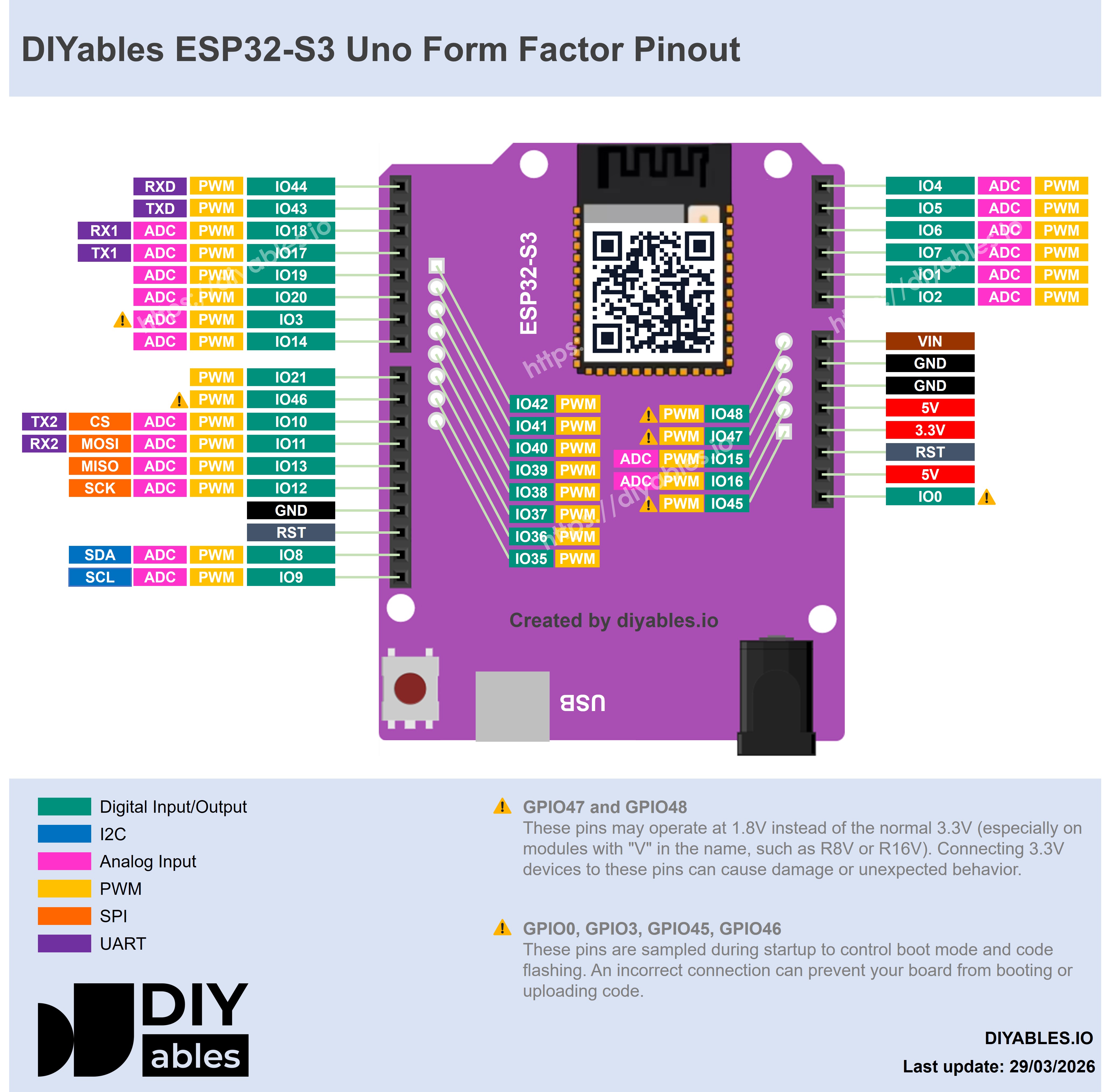
The ESP32 S3 Uno has the classic Uno headers, but the code uses the GPIO numbers of the ESP32-S3 chip. This project needs four pins on the digital header, D9 (GPIO46), D10 (GPIO10), D11 (GPIO11) and D12 (GPIO13), plus 5V and GND on the power header. All of these GPIOs can make PWM, but only D9 and D10 need it here. D11 and D12 just switch between HIGH and LOW.
Wiring Diagram
This project has two circuits that meet only on the module. The low-power one is six jumper wires from the ESP32 S3 Uno to the control header. The high-power one is the 12V adapter and the motor on the screw terminal. The GND-to-B- link inside the module ties the two together.
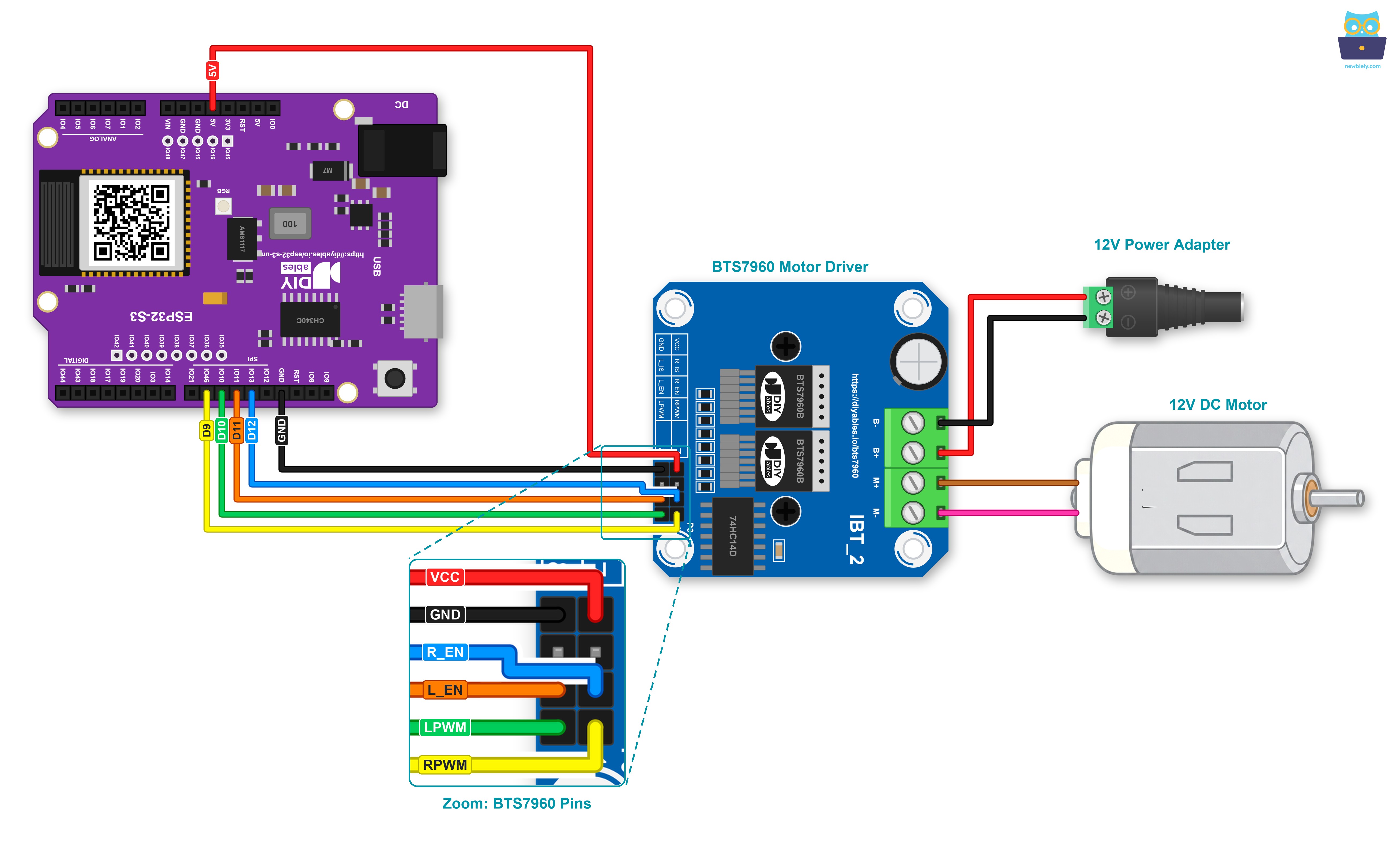
This image is created using Fritzing. Click to enlarge image
| BTS7960 Module | ESP32 S3 Uno / Other Part |
|---|---|
| RPWM | D9 (GPIO46) |
| LPWM | D10 (GPIO10) |
| R_EN | D12 (GPIO13) |
| L_EN | D11 (GPIO11) |
| VCC | 5V |
| GND | GND |
| R_IS, L_IS | not connected |
| B+ | + wire of the 12V adapter (via the DC power jack) |
| B- | - wire of the 12V adapter (via the DC power jack) |
| M+, M- | the two wires of the 12V DC motor |
Module wires and thick wires often do not sit well in the female headers. A Screw Shield V2 or a Proto Screw Terminal Block Shield solves this. Plug it into the ESP32 S3 Uno and screw the wires in. Here is the same circuit wired through the Screw Shield V2:
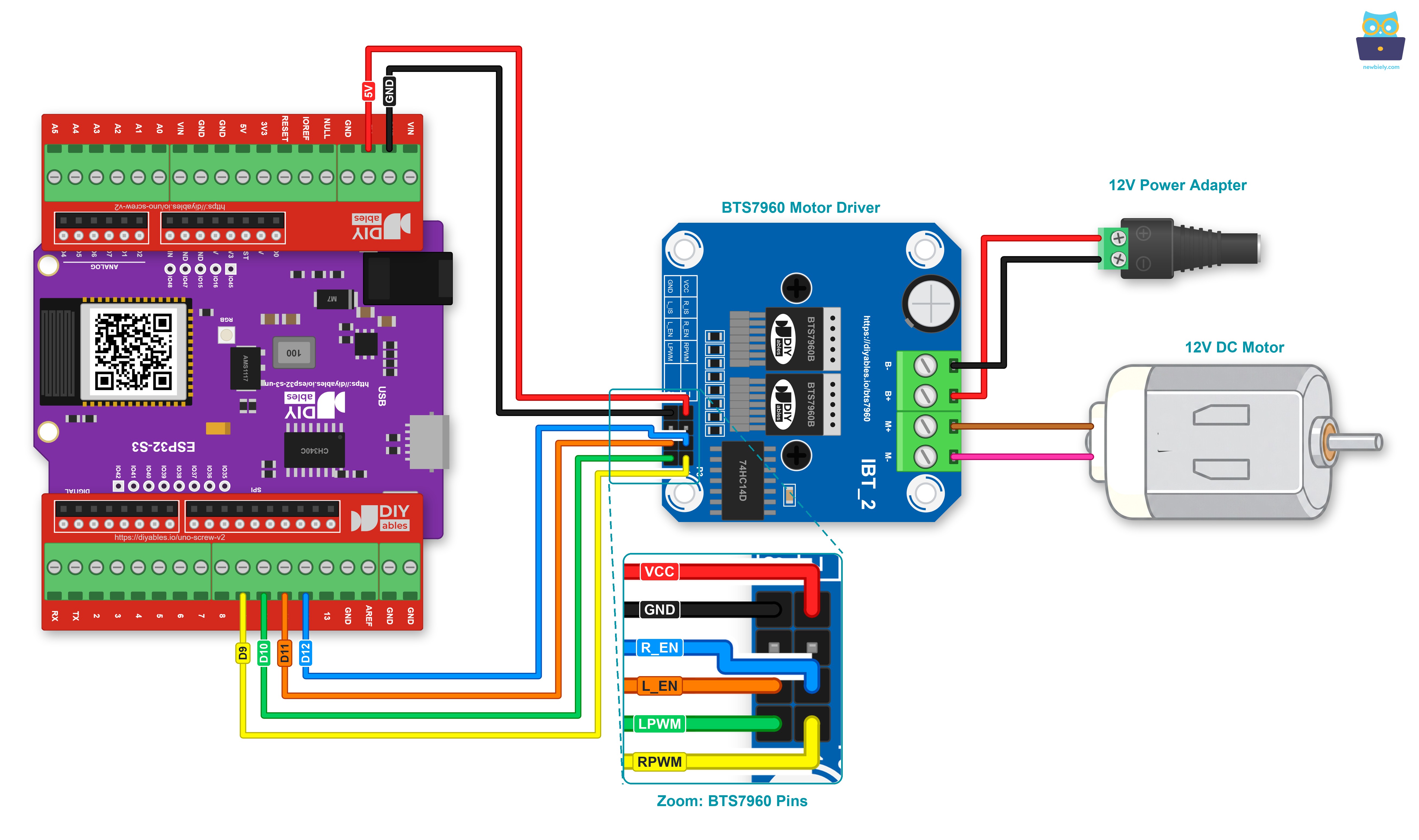
This image is created using Fritzing. Click to enlarge image
Watch the two enable wires: they cross. R_EN goes to D12 and L_EN goes to D11, so they are not in the same order as on the module.
WARNING
Look at + and - on the DC power jack before you plug in the 12V adapter. Wrong polarity on B+ and B- can damage the module. Keep B+ away from the ESP32 S3 Uno: 12V on any of its pins will destroy it.
※ NOTE THAT:
D9 is GPIO46, one of the boot strapping pins of the ESP32-S3. The chip checks its level at power-up. The RPWM input of the module normally leaves it alone. If the board ever does not start, or an upload fails while the module is wired, pull out the RPWM wire, upload, and then push it back in.
How To Program For BTS7960 Motor Driver
The BTS7960 needs no special commands. The code only writes PWM values and HIGH or LOW levels.
- Name the pins with GPIO numbers. On the ESP32 S3 Uno, header D9 is GPIO46, so the code writes 46:
- Wake the driver in a safe order. Both PWM pins go to 0 first, and only then the enable pins go HIGH. This way the motor cannot jump when the driver switches on:
- Drive one side at a time. For forward, clear LPWM first, then give RPWM a value from 0 to 255. Reverse is the mirror image, with the two pins swapped:
- Stop in one of two ways. Both PWM pins at 0 with the driver on is a brake. Both enable pins LOW is a coast:
On the ESP32 S3 Uno, analogWrite() takes a value from 0 to 255, just like on a classic Uno. The sketch puts each of these jobs in its own small function: motorForward(), motorReverse(), motorBrake() and motorCoast().
ESP32 S3 Uno Code - BTS7960 Motor Driver
The sketch repeats one test drive again and again: a slow start forward, two seconds at full power, a slow stop, a one-second brake, two seconds backing up at half speed, and two seconds of coasting. Each step prints one line, so you can match what the motor does with the text on the screen.
Detailed Instructions
- First time with this board? Install the ESP32 core in Arduino IDE with ESP32 S3 Uno - Getting Started.
- Leave the 12V adapter unplugged. Wire the six jumper wires, the motor and the DC power jack as the table shows.
- Connect the ESP32 S3 Uno to your computer with a USB Type-C cable.
- Select ESP32S3 Dev Module and the right COM port in Arduino IDE.
- Paste the code into a new sketch and click Upload.
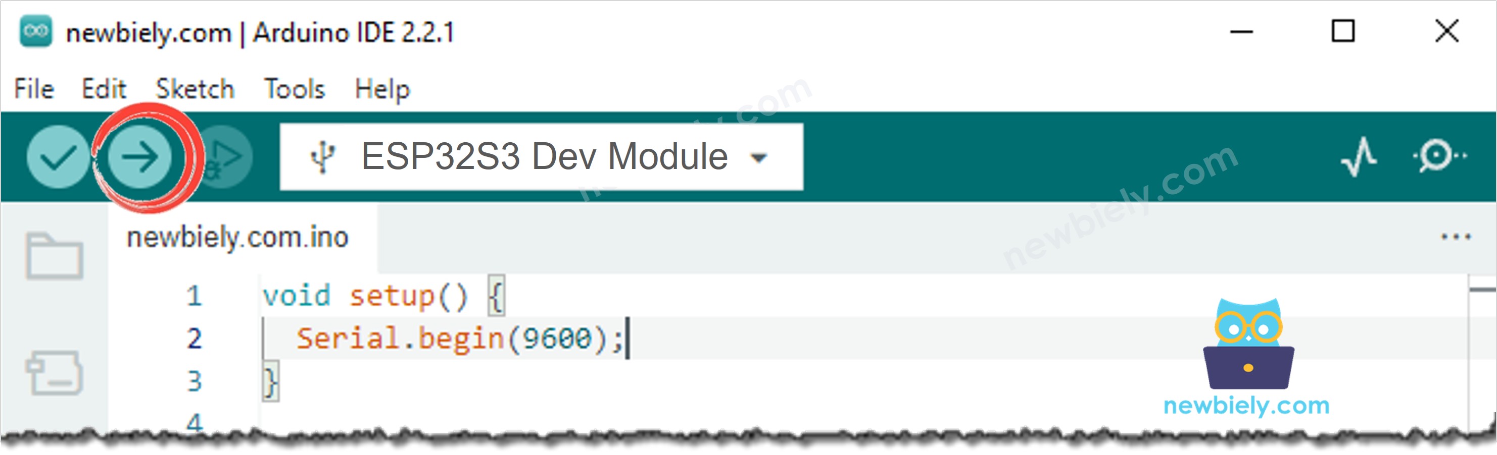
- Now plug in the 12V adapter. From this moment, the motor has power.
- Open the Serial Monitor at 9600 baud and watch the motor and the text together:
- Wrong direction? If the motor turns backward during the "forward" lines, unplug the 12V adapter and swap the M+ and M- wires on the screw terminal.
- A soft hum at low speed is normal. The PWM signal of the board runs at about 1 kHz, and the motor coils can sing a little at that speed.
Video Tutorial
Additional Knowledge
BTS7960 or L298N?
Both boards are H-bridges, and both take PWM for the speed. They suit very different motors:
| BTS7960 (this page) | L298N | |
|---|---|---|
| Motors per board | 1 | 2 |
| Current | up to 43A peak, much less for long runs | about 2A per motor |
| Voltage lost inside the driver | very little | about 2V |
| Good for | tracked bases, big gear motors, winches, wiper motors | small motors |
The L298N is handy when you need two small motors on one cheap board. The BTS7960 is the better pick when one motor needs a lot of current, or when you do not want to lose about 2V of your motor supply inside the driver. For small motors, a plug-on board is another easy path on this board: see ESP32 S3 Uno - DC Motor Shield.
Ideas for a tracked robot base
- Second track: add a second BTS7960 for the other track. Run one track forward and the other one in reverse, and the base turns on the spot.
- Joystick driving: read a stick with ESP32 S3 Uno - Joystick and turn its position into speed and direction.
- Wall guard: measure the distance with ESP32 S3 Uno - Ultrasonic Sensor and brake when something is closer than 30 cm.
- Phone remote: put Forward, Reverse and Stop buttons on a web page with ESP32 S3 Uno - Web Server.
- Speed dial: set the top speed with a knob, using ESP32 S3 Uno - Potentiometer.
Function References
FAQ
Why does VCC go to 5V on a 3.3V board?
VCC only feeds the 74HC14 buffer chip on the module, and the module maker asks for 5V there. The control pins still take 3.3V signals, so a HIGH from the ESP32 S3 Uno works without a level shifter. The motor does not need VCC at all: it takes its power from B+.
Can the module send 12V back into the ESP32 S3 Uno?
Not with this wiring. The four signal wires only carry signals out of the board, and R_IS and L_IS stay free. Just make sure B+ is never connected to the ESP32 S3 Uno.
Why does the code write 46, 10, 11 and 13?
The ESP32 core in Arduino IDE uses the GPIO numbers of the chip. D9 is GPIO46, D10 is GPIO10, D11 is GPIO11 and D12 is GPIO13. If you write 9 or 12, the code drives other pins.
What if RPWM and LPWM both get PWM?
Then the two halves of the bridge no longer work as a team, and the motor does not do what you asked. Keep one of them at 0 at all times. The helper functions in the sketch do this for you: each one clears the other side first.
Can one ESP32 S3 Uno drive both tracks of a tank base?
Yes. Give the second BTS7960 its own four control pins, for example D3 (GPIO17) for RPWM, D2 (GPIO18) for LPWM, D7 (GPIO14) for R_EN and D8 (GPIO21) for L_EN. Copy the defines and helper functions once more with those GPIO numbers. The second module also needs its VCC (5V) and GND wires. Leave D6 (GPIO3) free, because it is a boot strapping pin.
Troubleshooting
| Problem | Possible Cause | Solution |
|---|---|---|
| The steps scroll in the Serial Monitor, but the motor never moves | 12V adapter not plugged in, or R_EN / L_EN not wired | Plug in the adapter. Check the D11 and D12 wires and the VCC wire to 5V |
| Motor turns forward but never backward | LPWM wire loose or on the wrong pin | LPWM must go to D10, and the code must use 10 |
| Motor turns the wrong way | M+ and M- are swapped | Unplug the 12V adapter and swap the two motor wires |
| Motor gets slow or stops under load | The 12V adapter is too weak | Use an adapter that gives more current than the motor needs |
| Motor hums at low speed | PWM at about 1 kHz with a small duty cycle | This is normal. Use higher speed values if the motor does not start |
| Board does not start or upload with the module wired | D9 (GPIO46) is a boot strapping pin | Pull out the RPWM wire, upload, then plug it back in |
| No COM port in Arduino IDE | USB driver missing or charge-only cable | Install the CP210x or CH340 driver, use a data cable, or hold BOOT while you press RESET |
| Strange characters in the Serial Monitor | Baud rate does not match | Set the Serial Monitor to 9600 baud |