
Arduino UNO Q - ACS712 Current Sensor
How much current does your motor really pull? And what if it gets stuck and the current shoots up? The ACS712 sensor lets the Arduino UNO Q read the current of a load in amps. Then the Linux side of the board can send you a Telegram message the moment the load is overloaded.
In this tutorial, you will learn:
- How the ACS712 turns current into a voltage the MCU can read
- Why the UNO Q needs a small voltage divider between the sensor and its 3.3V analog pin
- How to program the MCU (C/C++) to measure DC current, with zero calibration at startup
- How to share the current value with the Linux side (Python) via Bridge
- How to get a Telegram alert when the current goes above 2 A (overload or a stalled motor)
- How to measure AC current (RMS)
- How to use OpenClaw on Arduino UNO Q with the ACS712
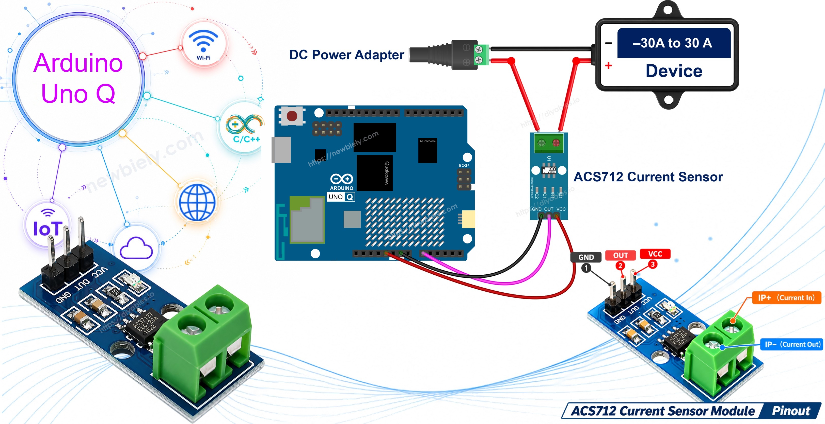
Hardware Preparation
Or you can buy the following kits:
| 1 | × | DIYables Sensor Kit (18 sensors/displays) |
Additionally, some of these links are for products from our own brand, DIYables .
Overview of the ACS712 Current Sensor
The ACS712 from Allegro measures current with the Hall effect. The current goes through a thick copper path inside the chip. This makes a small magnetic field, and a Hall sensor next to the path turns the field into a voltage. The load side and the Arduino side are not connected by any wire (2.1 kV RMS isolation), and the copper path is only about 1.2 mΩ, so the sensor hardly changes your circuit.
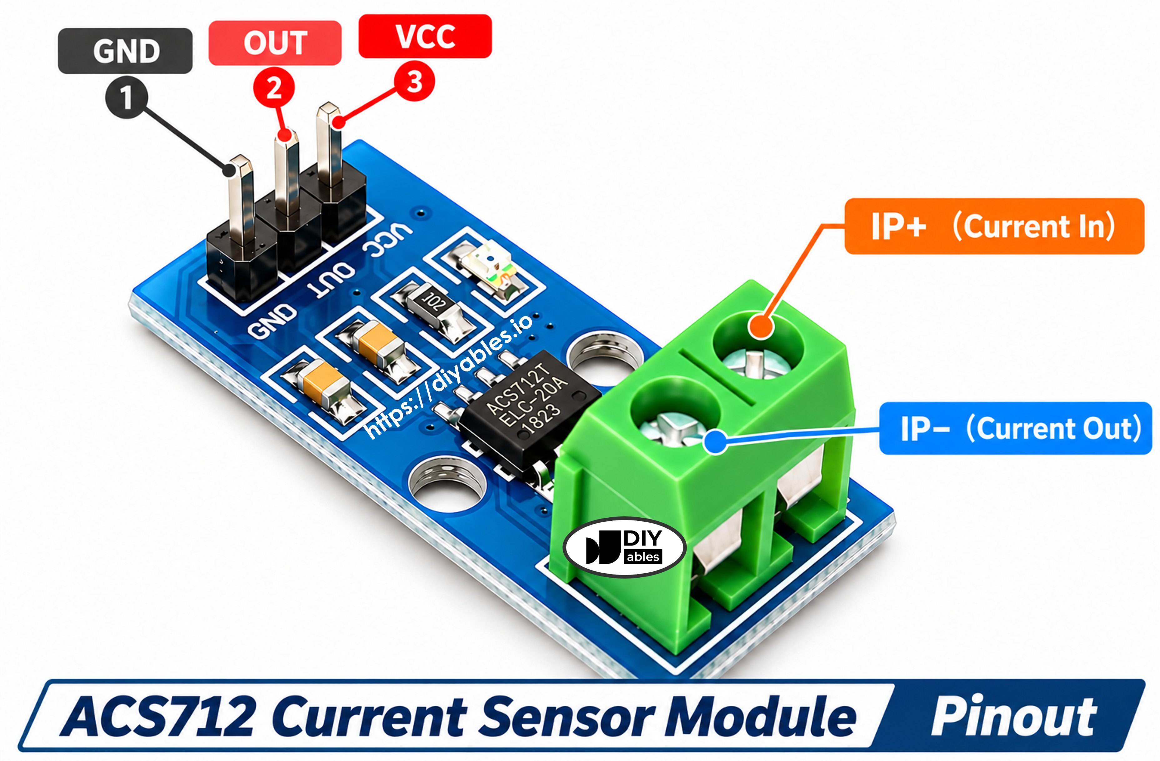
The module has two sides:
- 3-pin header (to the Arduino UNO Q):
- VCC: 5V power. The chip needs 4.5V to 5.5V — 3.3V is not enough.
- GND: Ground (0V)
- OUT: Analog voltage that shows the current
- 2-pin screw terminal (to the load): IP+ and IP−. It goes in series with the load: cut one supply wire of the load and put the terminal in between. Current that flows from IP+ to IP− gives a positive reading.
The red LED on the module only shows that it has power.
| ACS712 30A | |
|---|---|
| Chip | ACS712ELCTR-30A-T |
| Supply Voltage | 5V (4.5V to 5.5V) |
| Measuring Range | −30 A to +30 A (DC and AC) |
| Sensitivity | 66 mV per amp |
| Output at 0 A | about 2.5V (half of VCC) |
| Bandwidth | 80 kHz |
| Total Output Error | about ±1.5% at 25°C |
| Isolation | 2.1 kV RMS |
The same chip comes in three versions. They differ only in range and sensitivity:
| Version | Range | Sensitivity |
|---|---|---|
| ACS712 5A | ±5 A | 185 mV/A |
| ACS712 20A | ±20 A | 100 mV/A |
| ACS712 30A (this tutorial) | ±30 A | 66 mV/A |
From Volts to Amps
At 0 A the output sits near 2.5V. Current one way pushes it up, the other way pulls it down — 66 mV for every amp:
- +30 A: 2.5 + 30 × 0.066 ≈ 4.48V
- 0 A: about 2.5V
- −30 A: 2.5 − 30 × 0.066 ≈ 0.52V
So the formula is:
$$current\,(A) = \frac{V_{out} - V_{zero}}{0.066}$$
$V_{zero}$ is the real output at 0 A. It is rarely exactly 2.5V, so the code measures it at startup while no current flows.
※ NOTE THAT:
Small currents: the 30A version is made for loads of about 0.5 A and up — motors, lamps, LED strips, heaters, chargers. On the Arduino UNO Q, one ADC step is about 18 mA, and the sensor itself has some noise, so a reading of ±0.05 to 0.1 A with nothing connected is normal. Averaging many readings, as the code does, makes the value much calmer.
※ NOTE THAT:
Safety: mains AC (110V/220V) can kill. Practice with a low-voltage DC load like the 12V DC device in this tutorial. The screw terminal and the copper side carry the full voltage of the load — never touch them while a mains circuit is live.
Wiring Diagram
The Arduino UNO Q MCU (STM32U585) reads analog pins from 0V to 3.3V only. The ACS712 runs at 5V and its OUT pin can go up to about 4.5V. That is too high for A0. A simple divider fixes this: OUT → 10kΩ → A0 → 20kΩ → GND. A0 now sees 2/3 of the output (4.5V becomes 3.0V), and the code multiplies by 1.5 to get the real value back.
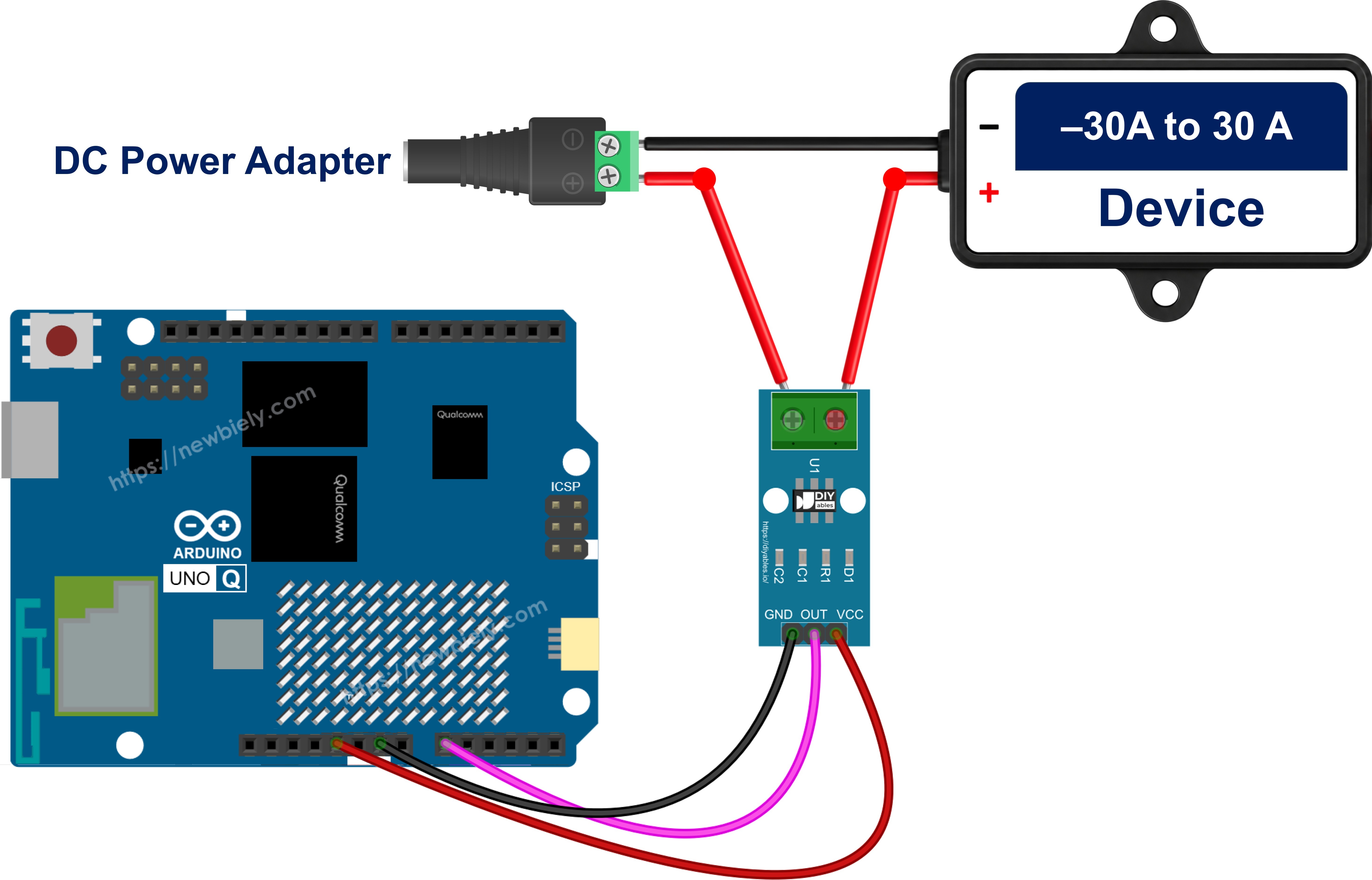
This image is created using Fritzing. Click to enlarge image
Sensor side (low voltage):
| ACS712 Pin | Arduino UNO Q MCU |
|---|---|
| VCC | 5V |
| GND | GND |
| OUT | 10kΩ resistor → A0 |
| (A0) | 20kΩ resistor → GND |
Load side (12V):
| From | To |
|---|---|
| 12V adapter (+) via DC power jack | ACS712 IP+ |
| ACS712 IP− | DC device (+) |
| DC device (−) | 12V adapter (−) via DC power jack |
The 12V circuit does not need to share ground with the Arduino UNO Q — the sensor keeps the two sides apart.
How To Program For ACS712
No library is needed. These are the key steps:
- Use the 12-bit ADC (0–4095, 3.3V reference) and set the sensor constants:
- Average many readings and turn the result back into the sensor's OUT voltage:
- At startup, with the load OFF, store the zero point (the code averages 1000 readings here):
- Convert to amps:
Arduino UNO Q Code
The Arduino UNO Q has two processors:
- The STM32 MCU reads the ACS712 on pin A0
- The Qualcomm MPU runs Debian Linux and has Wi-Fi
- Here only the MCU runs code. The Bridge section later gives the current value to Linux.
This sketch measures DC current. It finds the zero point once, then prints the sensor voltage and the current every 500 ms.
Detailed Instructions
First time with Arduino UNO Q? Read Getting Started with Arduino UNO Q first.
- Wire: Build the circuit from the wiring diagram. Check the 10kΩ/20kΩ divider twice — A0 must never get the raw OUT signal.
- Load OFF: Leave the 12V adapter unplugged for now.
- Open Arduino App Lab: Wait until it detects your Arduino UNO Q.
- Create a new App: Click Create New App.
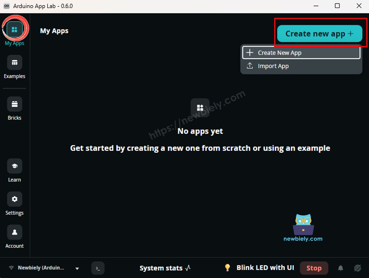
- Name it ACS712Current and click Create.
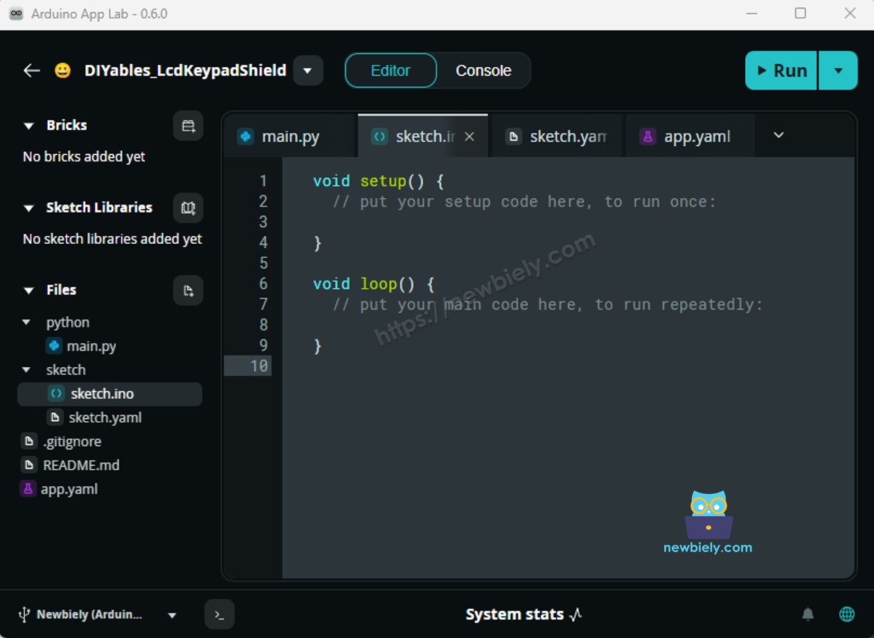
- Paste the sketch: Put the code above into sketch/sketch.ino. No library is needed.
- Run: Click the Run button.
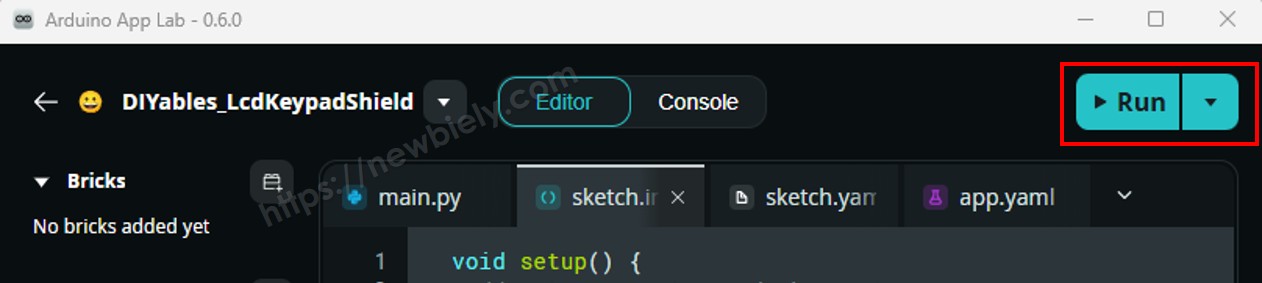
- Wait for "Zero point": Then plug in the 12V adapter so the DC device turns on.
- Test it: If your DC device is a motor, gently slow its shaft with your fingers (a short moment only) — the current goes up.
App Lab Console Output
The first lines are the idle noise with the DC device off. With a 12V DC motor as the DC device, it starts at about 0.8 A, and 1.32 A is the moment the shaft was slowed by hand. A negative value means the current flows from IP− to IP+ — swap the two load wires if you want positive numbers.
Bridge: Linux + MCU
Now let the Linux side read the current:
- The ACS712 is wired to the MCU's analog pin A0 — the MPU has no way to read it directly
- The MCU measures the current every 500 ms and keeps the latest value in memory
- It shares that value with Bridge.provide("get_current", ...)
- Python calls Bridge.call("get_current") and gets the cached value at once — the callback never waits for the ADC
- ⚠️ /dev/ttyHS1 (Linux) and Serial1 (MCU) are RESERVED by the router — never open them in user code
In short: MCU averages 200 readings → stores the amps → Python asks over Bridge → Linux can log it or send it online.
MCU Code (Bridge)
Python Code (Bridge)
Detailed Instructions
- Create a new App in Arduino App Lab, for example ACS712Bridge.
- Paste the MCU sketch into sketch/sketch.ino, and add the library:
- Install the library: Click the Add sketch library button (the open book icon with a + sign) in the left sidebar.
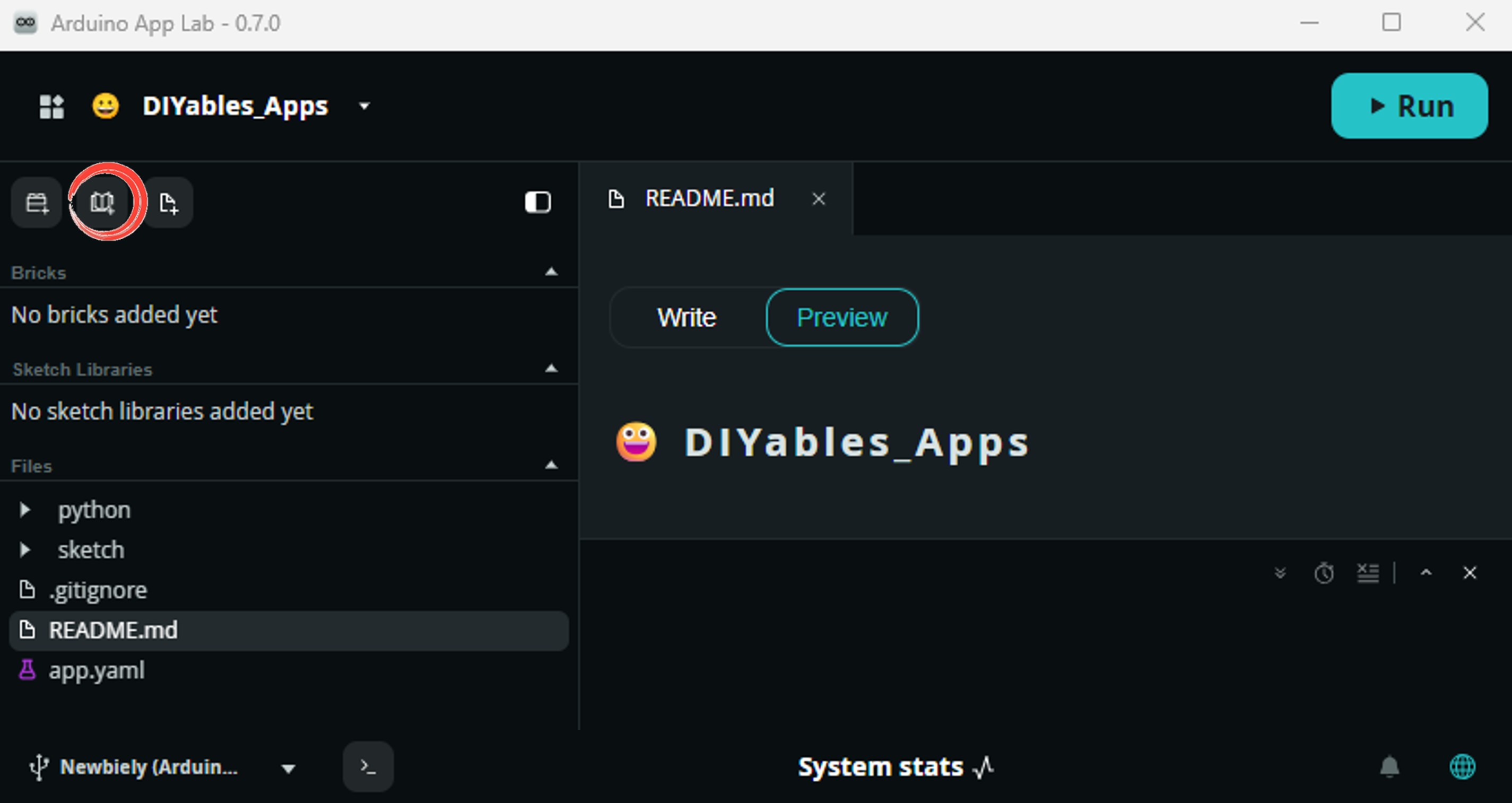
- Search for Arduino_RouterBridge created by Arduino and click the Install button.
- Paste the Python code into the Python file of the same App.
- Keep the load OFF, click the Run button, and switch the load on after the MCU prints "ready".
App Lab Console Output
Telegram
A jammed motor pulls much more current than a free-running one, and it gets hot fast. This bot watches the current and sends one message when it goes above 2.0 A. When the current falls under 1.5 A again, it sends an "all clear". The gap between the two numbers stops a flood of messages when the value sits near the limit.
MCU sketch: Keep the same MCU sketch from the Bridge section.
Python Code (Telegram)
Detailed Instructions
- Replace YOUR_TELEGRAM_BOT_TOKEN with your bot token from BotFather. New to bots? See How to Create a Telegram Bot.
- Replace YOUR_CHAT_ID with your Telegram chat ID — alerts go there.
- Paste this code into the Python file of your App (keep the Bridge MCU sketch).
- Click Run, then send /current to your bot.
- Pick the limit for your own load: measure its normal current first, then set CURRENT_ALERT_A a bit above it (and CURRENT_CLEAR_A a little lower).
App Lab Console Output


ArduinoBot
Measuring AC Current
The ACS712 can also measure AC current, but AC changes direction many times per second (50 or 60 Hz). A single reading lands anywhere on the wave, so it tells you nothing. Instead, the code samples for 200 ms (10 to 12 full cycles) and calculates the RMS value — the "effective" current that a clamp meter shows:
$$I_{RMS} = \frac{\sqrt{mean\big((V - V_{zero})^2\big)}}{0.066}$$
The wiring on the Arduino side is the same. The screw terminal goes in series with one wire of the AC load.
※ NOTE THAT:
Danger: this means working with mains voltage. If you are not trained for it, stop here or use a ready-made, closed power-monitor device. Never touch the screw terminal, the module, or loose wires while the plug is in the socket.
Arduino UNO Q Code — AC Current (RMS)
Detailed Instructions
- Keep the load unplugged, replace the code in sketch/sketch.ino with the sketch above, and click Run.
- After "Zero point" appears, switch on the AC load.
App Lab Console Output
Here a 1000 W kettle on 230V was switched on (1000 / 230 ≈ 4.35 A). With no load, the RMS value never reaches exactly 0 — the 0.06 to 0.07 A is sensor noise.
OpenClaw
You can adapt the OpenClaw to this tutorial by refering the instruction on Arduino Uno Q - OpenClaw Tutorial
Project Ideas
Ideas that use the ACS712 with both processors of the Arduino UNO Q:
- Motor Stall Guard: Switch a 12V motor through a relay and cut its power when the current stays above the limit for more than one second
- Battery Charger Log: Python records the charging current every minute to a CSV file and sends a Telegram message when it drops low (battery full)
- Power Use Report: Multiply current by the supply voltage to get watts, add it up on the Linux side, and send a daily watt-hour summary
- 3D Printer Watch: Follow the heater current of a 12V/24V printer and get a message when a print ends (current drops) or a heater stays on too long
- Appliance "Done" Notifier: With a trained person's help on the mains wiring, detect when a washing machine stops pulling current and send "laundry is done"
Challenge Yourself
Ready to go further with the ACS712 on Arduino UNO Q? Try these:
- Easy: Turn on the built-in LED in the MCU sketch while the current is above 1 A.
- Medium: Make the Python Bridge script keep the highest current since startup and print it next to every reading.
- Advanced: Add a /power Telegram command that uses the 12V supply value to report watts, plus the watt-hours used since the script started.