
Arduino UNO Q - DRV8833 DC Motor Driver
The DRV8833 is a tiny, cool-running driver that can spin two small DC motors from a battery pack — a perfect fit for a first robot car built on the Arduino UNO Q. The STM32 MCU produces the PWM signals, and the Linux side can later take over as the "remote control" through Bridge and Telegram.
In this tutorial, you will learn:
- What the DRV8833 module does and what each of its pins is for
- How the IN1/IN2 truth table gives forward, reverse, coast, and brake
- How to program the Arduino UNO Q MCU to drive ONE DC motor with speed ramping
- How to drive TWO DC motors like a small robot car (forward, backward, left, right)
- How to steer the two-motor car from the Linux side (Python) through Bridge
- How to drive the car from your phone with Telegram commands
- How to use OpenClaw on Arduino UNO Q with the DRV8833
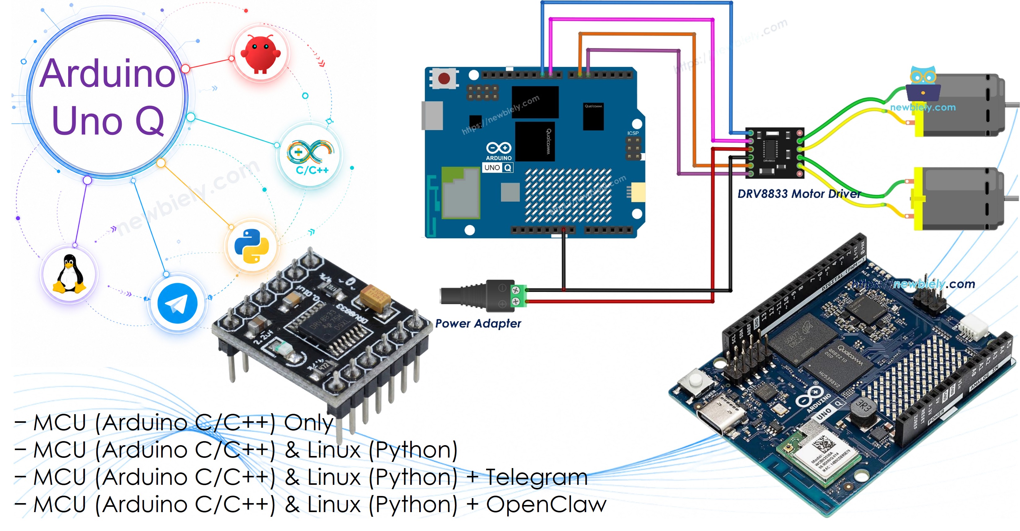
Hardware Preparation
Or you can buy the following kits:
| 1 | × | DIYables Sensor Kit (18 sensors/displays) |
Additionally, some of these links are for products from our own brand, DIYables .
Part 1 needs only one motor. The second motor is for Part 2.
Overview of the DRV8833 Module
The DRV8833 is a dual H-bridge chip from Texas Instruments. One module can run two brushed DC motors in both directions (or one small bipolar stepper motor). Its outputs use MOSFETs, so very little voltage is lost inside the chip — your motors get almost the full battery voltage and the board stays cool, unlike the older L298N.
| DRV8833 | |
|---|---|
| Motor Supply (VCC / VM) | 2.7V to 10.8V |
| Logic Input Level | 3.3V or 5V (no separate logic supply needed) |
| Output Current | about 1.5A RMS per channel, 2A peak |
| Channels | 2 (motor A and motor B) |
| PWM Frequency | up to 50 kHz |
| Protection | under-voltage, over-current, over-temperature |
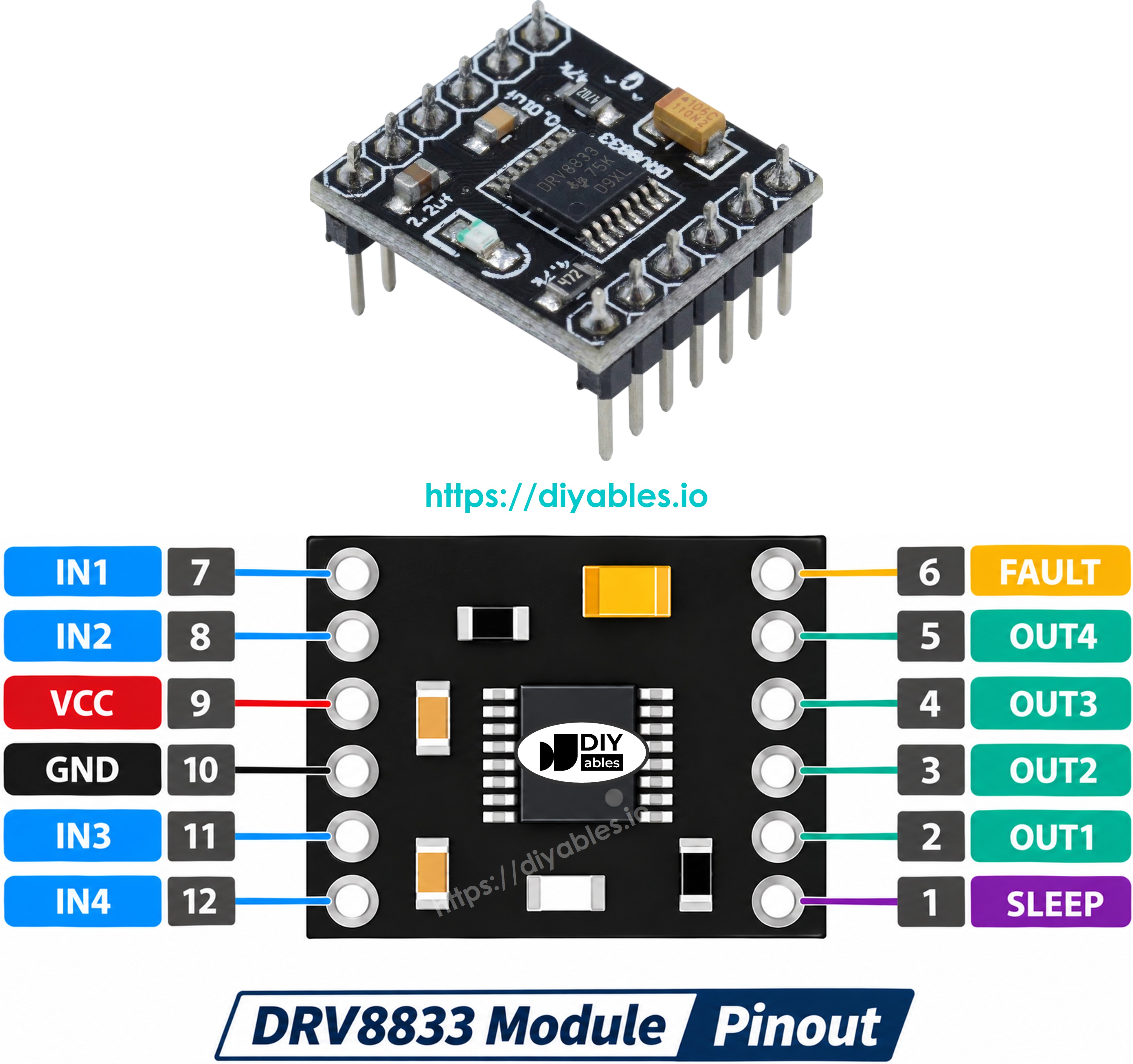
Control pins (to the Arduino UNO Q MCU):
- IN1, IN2: Control motor A — direction and speed (PWM)
- IN3, IN4: Control motor B — direction and speed (PWM)
- EEP: Enable pin (nSLEEP). Must be HIGH for the driver to work — connect it to 3.3V. LOW puts the chip to sleep.
- ULT: Fault output (nFAULT). Goes LOW on over-current or over-heat. Optional — you can leave it unconnected.
Power and motor pins:
- VCC: Motor power, 2.7V to 10.8V, from an external supply
- GND: Ground — shared by the supply, the module, and the Arduino UNO Q
- OUT1, OUT2: Motor A wires
- OUT3, OUT4: Motor B wires
Labels vary between makers: some boards print AIN1/AIN2/BIN1/BIN2, AOUT1/AOUT2/BOUT1/BOUT2, SLP and FLT instead. The job of each pin is the same.
Truth Table — How the DRV8833 Moves a Motor
There is no ENA/ENB speed pin like on the L298N. Each motor is controlled by just its two IN pins:
| IN1 | IN2 | Motor A |
|---|---|---|
| LOW | LOW | Coast (free-runs to a stop) |
| HIGH | LOW | Forward |
| LOW | HIGH | Reverse |
| HIGH | HIGH | Brake (fast stop) |
For speed, send PWM to one IN pin and hold the other LOW: PWM on IN1 for forward, PWM on IN2 for reverse. That is why all four IN pins must go to PWM-capable pins of the Arduino UNO Q. Motor B (IN3/IN4) works the same way.
※ NOTE THAT:
- Power the motors from the external supply on VCC — never from the 3.3V or 5V pin of the Arduino UNO Q.
- The GND of the power supply, the DRV8833, and the Arduino UNO Q must all be connected together.
- For one bigger motor you can join both channels to get about 3A, but that is not needed for small 5V motors.
Part 1 — Control One DC Motor
Wiring Diagram
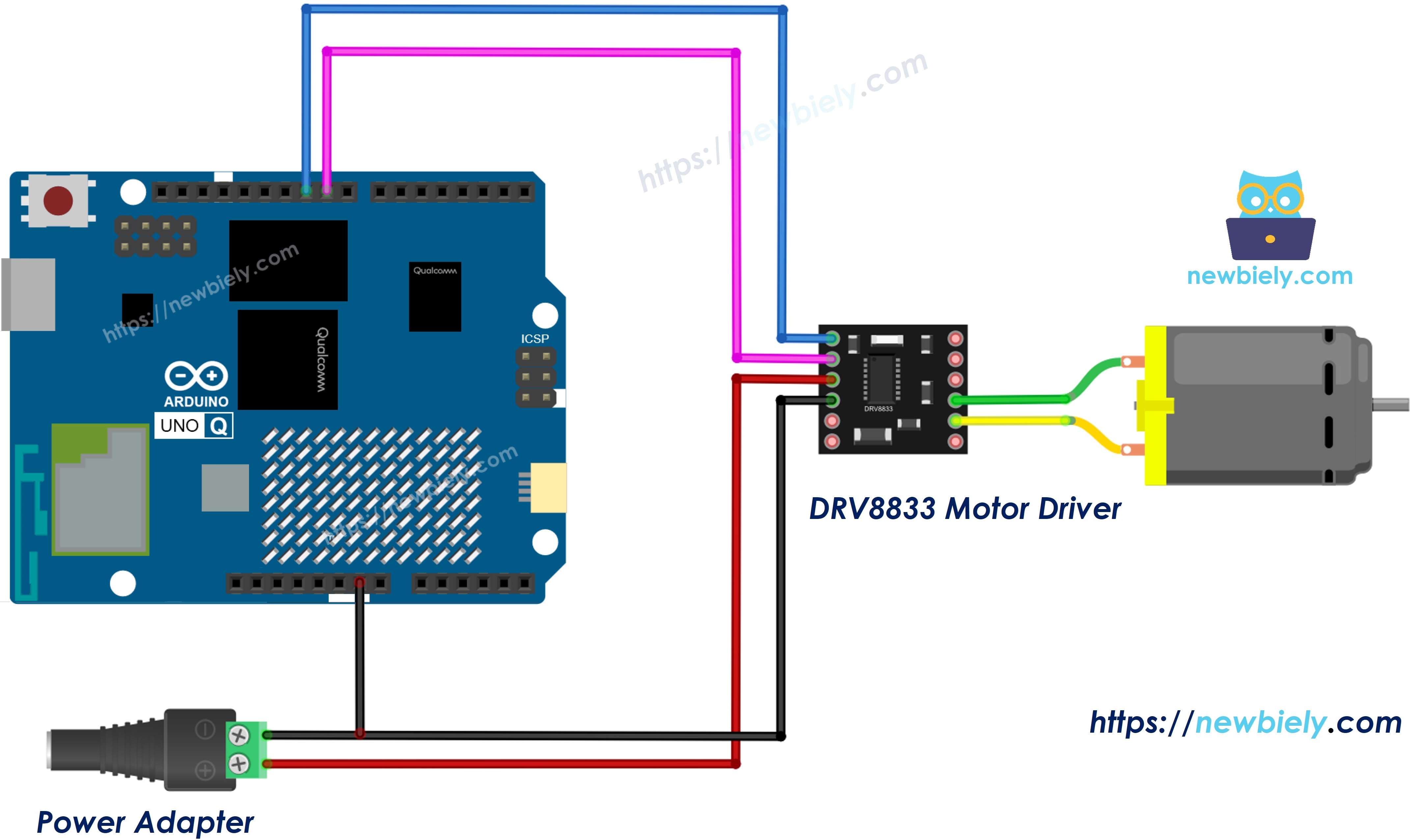
This image is created using Fritzing. Click to enlarge image
| DRV8833 Pin | Connect To |
|---|---|
| IN1 | Arduino UNO Q D10 (PWM) |
| IN2 | Arduino UNO Q D9 (PWM) |
| EEP | Arduino UNO Q 3.3V |
| GND | Arduino UNO Q GND and power supply (-) |
| VCC | 5V power supply (+) via DC power jack |
| OUT1, OUT2 | DC motor wires |
How To Program For DRV8833
- Pick two PWM pins for motor A and set them as outputs:
- Spin forward at a chosen speed (0 to 255) — PWM on IN1, IN2 LOW:
- Spin in reverse — IN1 LOW, PWM on IN2:
- Coast (outputs off, the motor rolls to a stop):
- Brake (fast stop):
The sketch wraps these lines in one helper, motorA(speed), where a positive speed means forward and a negative speed means reverse.
Arduino UNO Q Code — One Motor
The Arduino UNO Q has two processors:
- The STM32 MCU creates the PWM signals for the DRV8833 — motor timing is real-time work, so it lives here
- The Qualcomm MPU runs Debian Linux with Wi-Fi and Python
- Here only the MCU is programmed. The Linux side joins in the Bridge section below.
The sketch ramps the motor up in the forward direction, holds full speed, coasts, reverses at speed 150, and finally brakes — printing each step.
Detailed Instructions
New to Arduino UNO Q? Start with the Getting Started with Arduino UNO Q tutorial.
- Wire it up: Connect the DRV8833, one motor, and the 5V adapter as in the wiring diagram. Double-check that EEP goes to 3.3V and all grounds are joined.
- Connect: Plug the Arduino UNO Q into your computer with the USB-C cable.
- Open Arduino App Lab: Wait until it finds your Arduino UNO Q.
- Create a new App: Click the Create New App button.
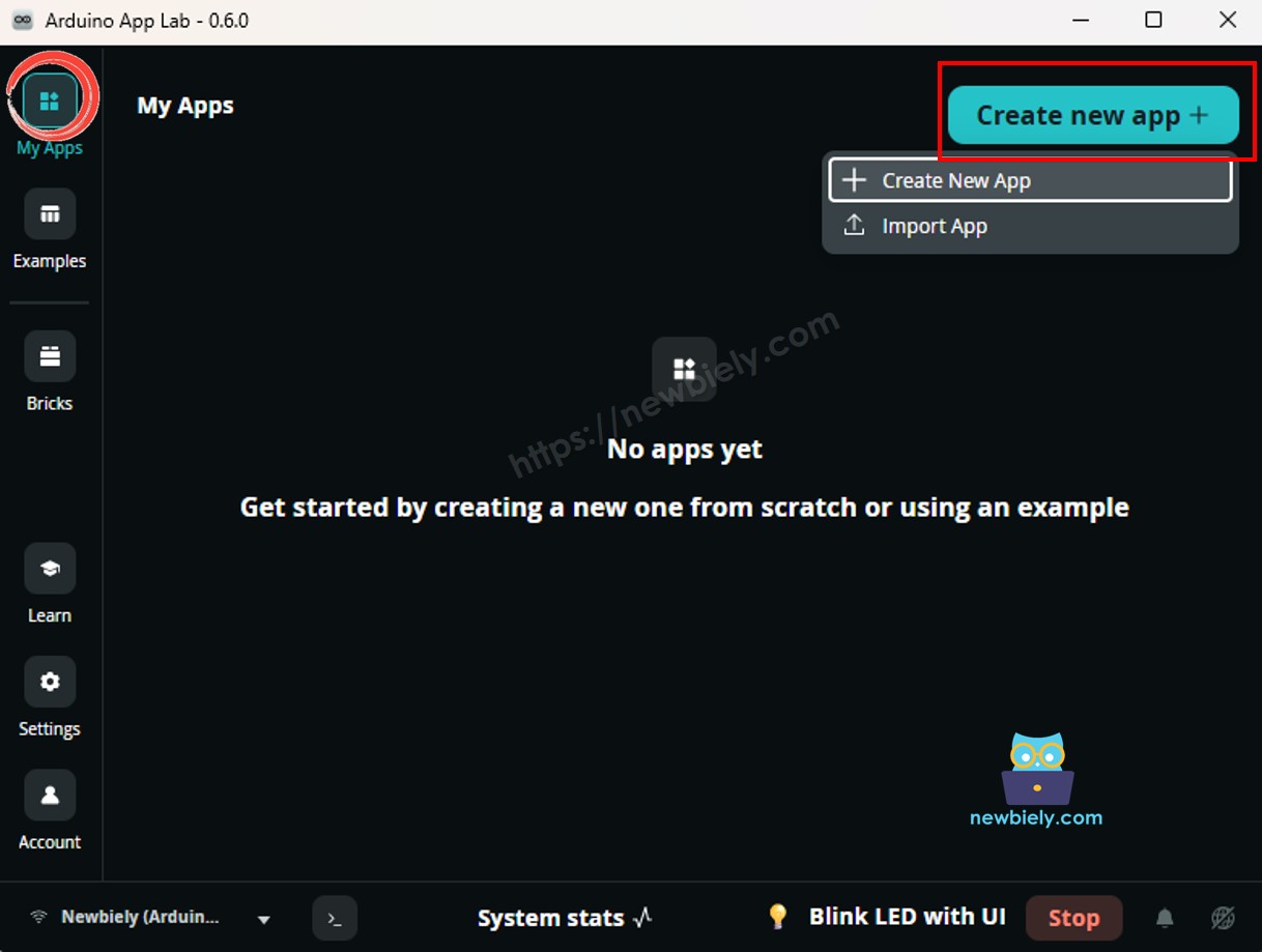
- Name it, for example DRV8833OneMotor, and click Create.
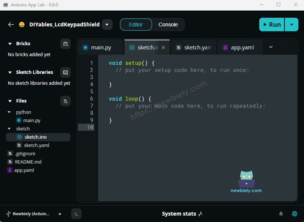
- Paste the sketch: Copy the code above into sketch/sketch.ino. Leave the other files as they are. No extra library is needed — the sketch uses only analogWrite() and digitalWrite().
- Run: Click the Run button.
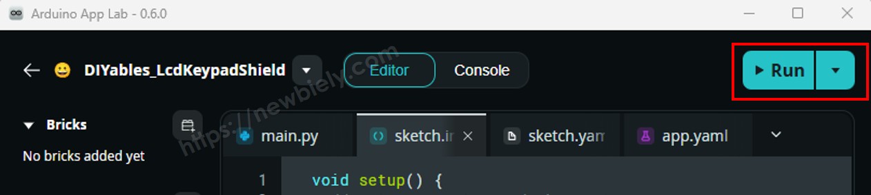
- Watch the motor: It speeds up slowly, runs fast, rolls to a stop, turns the other way, then stops sharply on the brake step. If "forward" turns the wrong way, swap the two wires on OUT1/OUT2.
App Lab Console Output
You can hear the difference: on Coast the motor winds down for a moment, while on Brake it stops almost at once.
Part 2 — Control Two DC Motors
Now use both channels. Think of a two-wheel robot car: motor A is the left wheel, motor B is the right wheel. Turning is done by spinning the wheels in opposite directions.
Wiring Diagram
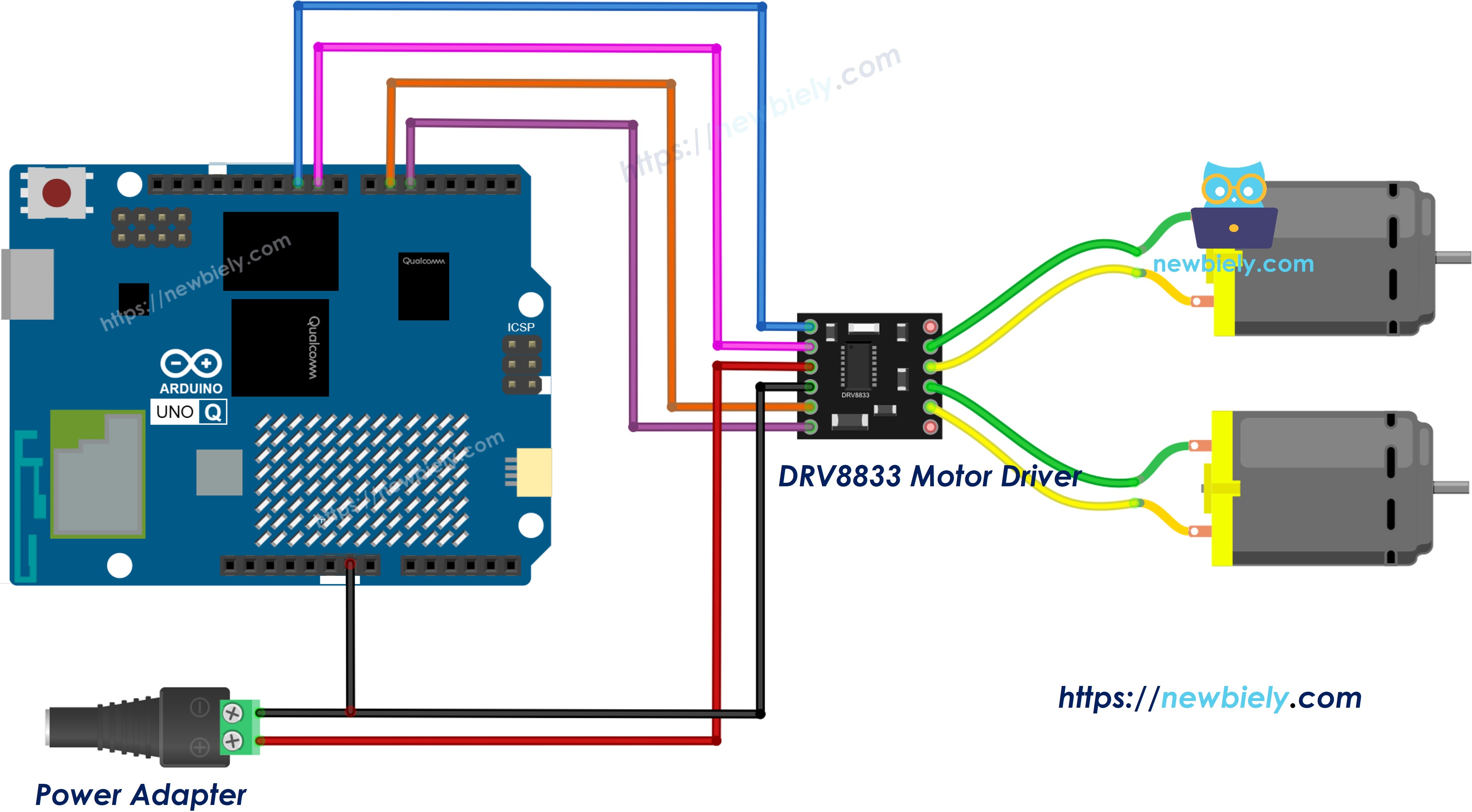
This image is created using Fritzing. Click to enlarge image
| DRV8833 Pin | Connect To |
|---|---|
| IN1 | Arduino UNO Q D10 (PWM) |
| IN2 | Arduino UNO Q D9 (PWM) |
| IN3 | Arduino UNO Q D6 (PWM) |
| IN4 | Arduino UNO Q D5 (PWM) |
| EEP | Arduino UNO Q 3.3V |
| GND | Arduino UNO Q GND and power supply (-) |
| VCC | 5V power supply (+) via DC power jack |
| OUT1, OUT2 | Left motor (motor A) |
| OUT3, OUT4 | Right motor (motor B) |
Arduino UNO Q Code — Two Motors
The sketch adds a setMotor() helper that works for either channel, then builds five car moves from it: forward, backward, turn left (A reverse, B forward), turn right, and stop.
Detailed Instructions
- Wire the second motor to OUT3/OUT4 and connect IN3 → D6, IN4 → D5.
- Create a new App in Arduino App Lab (for example DRV8833TwoMotors), paste the sketch into sketch/sketch.ino, and click Run.
- Lift the wheels off the desk, or the "car" will drive away! Watch both motors go through the move sequence.
App Lab Console Output
Bridge: Linux + MCU
Keep the Part 2 wiring. In this section, the Linux side becomes the "driver" of the car:
- The DRV8833 is wired to the MCU (STM32) — only the MCU can write PWM to IN1..IN4
- The MPU (Linux) sends commands with Bridge.call() — forward, backward, left, right, stop, brake
- set_speed takes a number (0..255), so Python can change the speed while the car runs
- The motor functions touch hardware pins, so the MCU registers them with Bridge.provide_safe()
- ⚠️ /dev/ttyHS1 (Linux) and Serial1 (MCU) are RESERVED by the router — never open them in your code
In short: Python calls a move → MCU sets the IN pins → DRV8833 drives both motors.
MCU Code (Bridge)
Python Code (Bridge)
The Python script runs a short demo route: forward, left, right at speed 150, then backward at speed 230, brake, and stop.
Detailed Instructions
- Create a new App: In Arduino App Lab click Create New App, name it DRV8833Bridge, and click Create.
- Paste the MCU sketch into sketch/sketch.ino.
- Install the library: Click the Add sketch library button (the open book icon with a + sign) in the left sidebar.
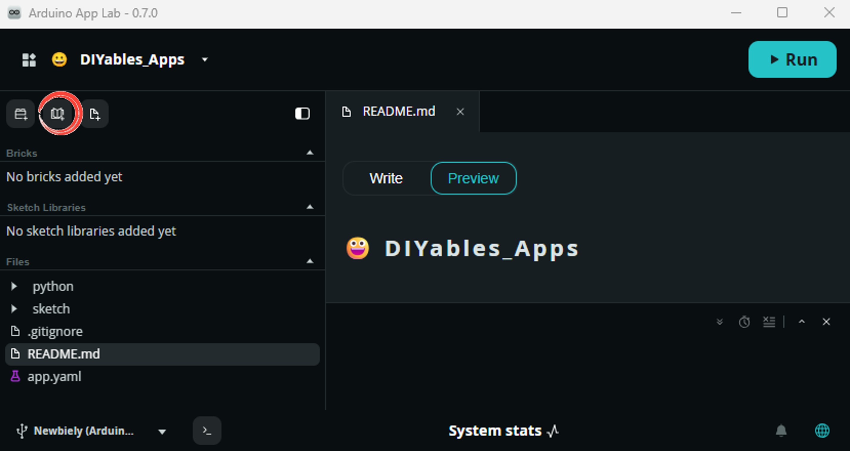
- Search for Arduino_RouterBridge created by Arduino and click the Install button.
- Paste the Python code into the Python file of the same App.
- Run: Click the Run button. The car repeats the demo route.
- Check both consoles: The MCU Monitor shows what the motors do; the Python console shows what Linux asked for.
App Lab Console Output
Telegram
Drive the two-motor car from your phone. Each move command starts the motors, and /stop or /brake ends it. As a safety net, the script stops the car by itself if no new command arrives within 10 seconds — handy if your phone loses signal.
Need a bot first? See How to Create a Telegram Bot.
MCU sketch: Keep the Bridge MCU sketch from the previous section — no change.
Python Code (Telegram)
Detailed Instructions
- Replace YOUR_BOT_TOKEN with the token from @BotFather.
- Paste the code into the Python file of your App (the MCU sketch stays the same).
- Click Run, then open your bot in Telegram and send /forward.
- Try /speed 120 followed by /forward to drive slower, and /left or /right to turn.
App Lab Console Output


ArduinoBot
OpenClaw
You can adapt the OpenClaw to this tutorial by refering the instruction on Arduino Uno Q - OpenClaw Tutorial
Project Ideas
Some builds that suit the DRV8833 and the two brains of the Arduino UNO Q:
- Wi-Fi Robot Car: Two motors on a small chassis, steered from Telegram — the Linux side handles the network, the MCU handles the wheels
- Battery Line Follower: Run on 4 x AA batteries (about 6V) and add IR sensors; the low-loss DRV8833 keeps more power for the wheels
- Motorized Blinds: One channel rolls a blind up or down; the Linux side opens it at sunrise on a schedule
- Pet Treat Spinner: A small geared motor turns a dispenser wheel when you send a Telegram command
- Desk Fan Mixer: Two small fans at different PWM speeds, set from a Python script based on room temperature
Challenge Yourself
Ready to push the DRV8833 further on the Arduino UNO Q?
- Easy: Wire the ULT (fault) pin to a digital input with INPUT_PULLUP and print a warning when it goes LOW.
- Medium: Add a set_motors(int, int) Bridge function that takes a signed speed for each wheel, so Python can make smooth curves instead of sharp turns.
- Advanced: Use EEP as a GPIO output: put the driver to sleep when the car has been stopped for 30 seconds and wake it on the next Telegram move command, then report the idle time with a /status command.