
Raspberry Pi - IR Slotted Optical Speed Sensor
This tutorial instructs you how to use Raspberry Pi to read the pulses from an IR slotted optical speed sensor with a short Python script. You may also know this part as a photo interrupter or an opto interrupter. It sees when something passes through its narrow gap. With that one signal, the Raspberry Pi can count objects, or it can tell how fast a wheel or a motor shaft turns. In detail, we will learn:
- What happens inside the U-shaped IR sensor when the gap is open and when it is blocked
- How to connect the IR slot sensor to the GPIO header of a Raspberry Pi 4 at 3.3V
- How to program Raspberry Pi to count every object that goes through the slot
- How to program Raspberry Pi to measure the speed of a motor in RPM with an encoder disc and a GPIO event callback
We suggest:
- Utilizing a rotary encoder when you want a hand-turned knob that also tells the direction of rotation.
- Utilizing an infrared obstacle avoidance sensor when the object is in front of the sensor, a few centimeters away, and cannot fit inside a slot.
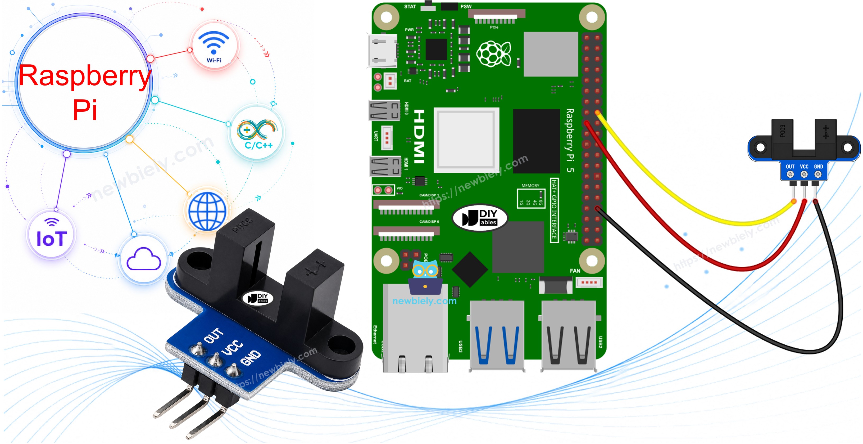
Hardware Preparation
Or you can buy the following kits:
| 1 | × | DIYables Sensor Kit (18 sensors/displays) |
Additionally, some of these links are for products from our own brand, DIYables .
Overview of IR Slotted Optical Speed Sensor
Look at the module from the side and you will see the letter U. The two arms of the U face each other across a gap that is 5.9 mm wide. One arm holds an infrared LED. The other arm holds an NPN phototransistor. The LED shines across the gap all the time, and the phototransistor watches for that light.
| IR Slotted Optical Speed Sensor | |
|---|---|
| Sensor type | slot-type photoelectric (IR LED + NPN phototransistor) |
| Slot width | 5.9 mm |
| Operating voltage | 3.3V to 5V DC |
| Output | digital (TTL), LOW when blocked, HIGH when clear |
| Signal conditioning | built-in Schmitt trigger |
| Mounting | M3 screw holes at both ends |
| Pins | 3 (VCC, GND, OUT) |
People use this sensor for jobs like these:
- Measuring the speed (RPM) of a motor that has an encoder disc
- Building a simple tachometer
- Counting objects or pulses
- Measuring distance by counting how many times a wheel turns
- Giving speed feedback for the wheels of a robot
- Detecting a limit or a home position
How It Works

The OUT pin follows the light beam:
- Empty gap: the infrared light gets to the phototransistor, so OUT stays HIGH.
- Something opaque in the gap (a piece of card, or one tooth of an encoder disc): the light cannot get across, so OUT drops to LOW.
There is also a Schmitt trigger on the board. It turns the raw signal into a clean 0 or 1 with no jitter at the edges. Because of this, your Python script does not need any debounce code.
Two small things to keep in mind:
- Clear plastic or glass may let the IR light pass, so the sensor may not see it. Use opaque objects.
- A few modules from other makers work the other way round. If your module reports "blocked" while the gap is empty, swap LOW and HIGH in the first script. The RPM script counts one edge for each tooth, so it gives the right speed either way.
The IR Slotted Optical Speed Sensor Pinout
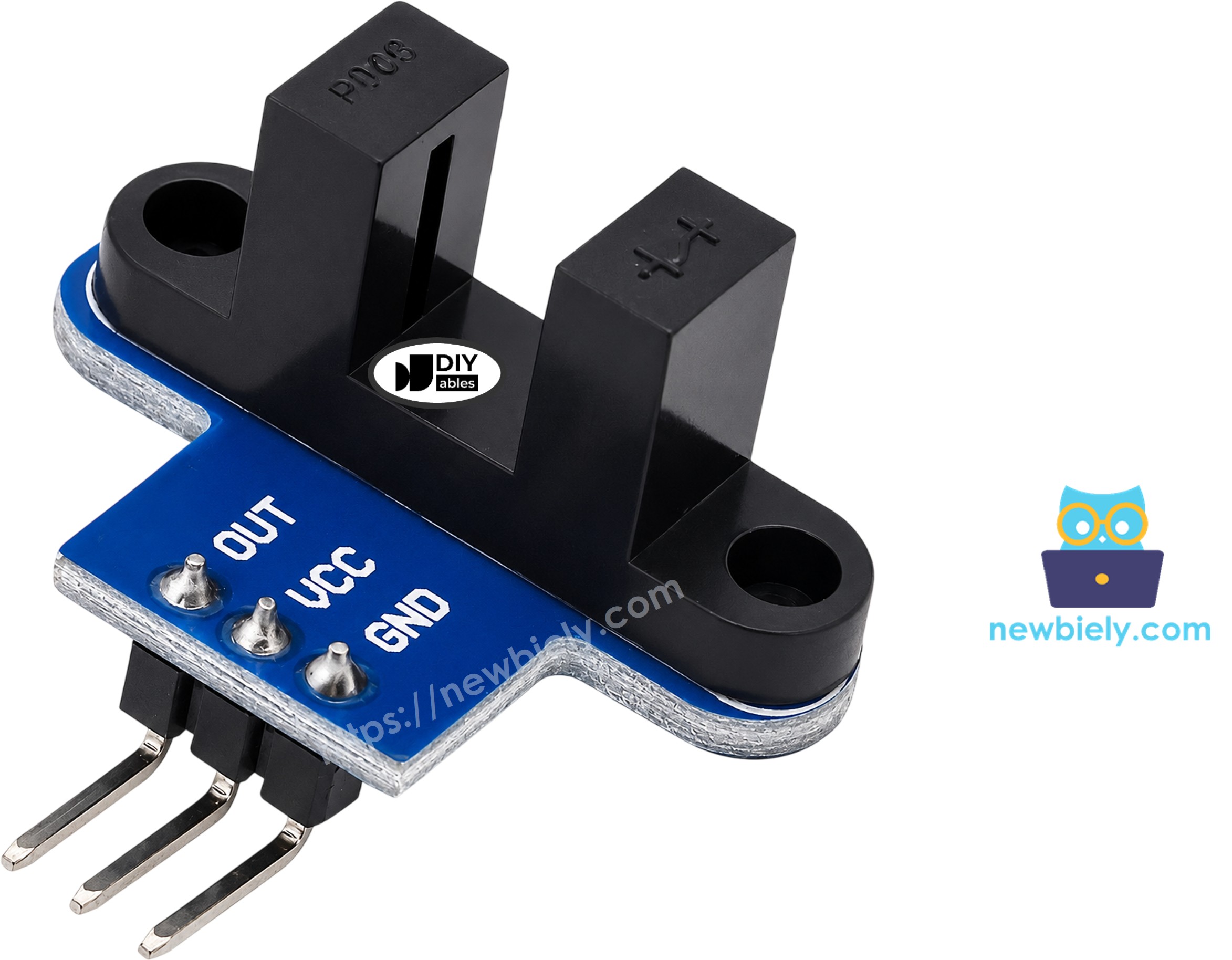
The module has three pins:
- VCC: This pin must be connected to the voltage supply (3.3V to 5V). On the Raspberry Pi, use 3.3V.
- GND: This pin must be connected to ground (0V)
- OUT: This pin sends the digital signal to a GPIO input pin of the Raspberry Pi
※ NOTE THAT:
The arrangement of pins on a module can differ between manufacturers, and even between batches. It is essential to always use the labels printed on the module when working with it. Be sure to take a close look!
Wiring Diagram
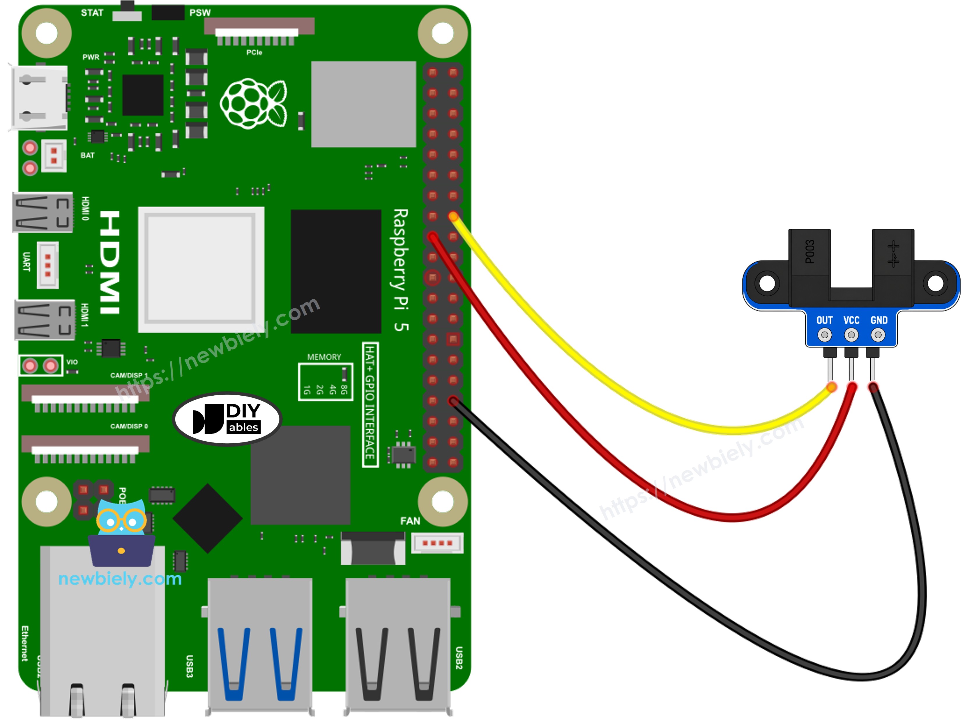
This image is created using Fritzing. Click to enlarge image
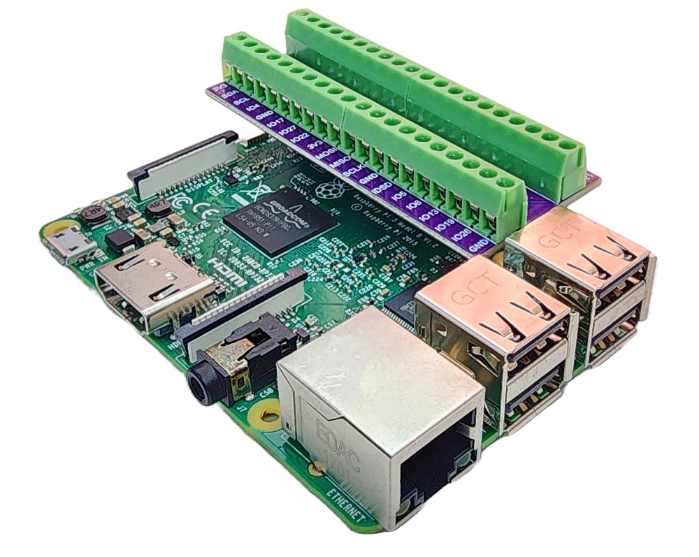
To simplify and organize your wiring setup, we recommend using a Screw Terminal Block Shield for Raspberry Pi. This shield ensures more secure and manageable connections, as shown below:
- Sensor VCC pin to Raspberry Pi 3.3V (pin 1)
- Sensor GND pin to Raspberry Pi GND (pin 6 or any other GND pin)
- Sensor OUT pin to Raspberry Pi GPIO17 (pin 11)
WARNING
Do not power this sensor from the 5V pin of the Raspberry Pi. The OUT pin goes as high as the VCC voltage. With 5V on VCC, OUT would send 5V into GPIO17, but the Raspberry Pi GPIO pins accept 3.3V only. Powering the sensor from 3.3V keeps the OUT signal safe.
Encoder Disc Setup for Speed Measurement
The second script needs an encoder disc. This is a round disc with slots cut around its edge.
- Fix the disc on the motor shaft or on the wheel.
- Mount the sensor with its M3 screw holes, so the edge of the disc runs inside the gap.
- Check that the teeth of the disc pass through the slot without touching the sensor arms.
You can spin the disc by hand, or you can run the motor. The motor wiring is not part of this page. To drive a motor from the Raspberry Pi, see the Raspberry Pi - DC Motor tutorial.
How To Program for Raspberry Pi to Detect and Count Objects with IR Slotted Optical Speed Sensor
This first script checks GPIO17 again and again in a loop. It prints a line only when the state of the pin changes. Each time the gap becomes blocked, the count goes up by one.
Detailed Instructions
- Make sure you have Raspbian or any other Raspberry Pi compatible operating system installed on your Pi.
- Make sure your Raspberry Pi is connected to the same local network as your PC.
- Make sure your Raspberry Pi is connected to the internet if you need to install some libraries.
- If this is the first time you use Raspberry Pi, See how to set up the Raspberry Pi
- Connect your PC to the Raspberry Pi via SSH using the built-in SSH client on Linux and macOS or PuTTY on Windows.
- Make sure the RPi.GPIO library is installed. If it is missing, install it with these commands:
- Wire the sensor to the Raspberry Pi as shown in the wiring diagram above.
- Create a Python script file OpticalSpeedSensor.py and add the following code:
- Save the file and start the script with this command:
- Slide a piece of card, or your finger, into the gap and pull it out again. Do it a few times.
- Check the results on the terminal.
The terminal stays quiet while nothing changes. A new line shows up only at the moment the gap gets blocked or becomes clear again. The script keeps watching until you press Ctrl + C keys in the terminal. It then cleans up the GPIO pin before it exits.
How To Program for Raspberry Pi to Measure Motor Speed (RPM) with IR Slotted Optical Speed Sensor
When a disc spins fast, the pulses come very quickly. A simple loop like the one above could miss some of them. So this script asks RPi.GPIO to watch the pin in the background with GPIO.add_event_detect(). Each FALLING edge (the moment a tooth blocks the gap) calls a small function that adds one to a counter. In this way, each tooth gives exactly one count.
Once per second, the script reads the counter, sets it back to zero, and works out the speed:
- One full turn of a 20-slot disc gives 20 pulses.
- Pulses in 1 second × 60 = pulses in 1 minute.
- Pulses in 1 minute ÷ 20 = turns in 1 minute, which is the RPM.
The value 20 is stored in SLOTS_PER_TURN. That is the slot count of the common encoder disc sold with TT gear motors. If your disc has a different number of slots, change this constant.
Detailed Instructions
- Do the same preparation as in the first example: SSH into the Raspberry Pi, install RPi.GPIO, and keep the same wiring.
- Put the encoder disc in place, as shown in the encoder disc setup above.
- Create a Python script file OpticalSpeedSensorRPM.py and add the following code:
- Save the file and start the script with this command:
- Spin the disc by hand, or turn on the motor.
- Check the results on the terminal. The lines below come from a motor that turns at about 300 RPM:
Unlike the first script, this one prints a line every 1 second (from the time.sleep(1) line), even when the disc is not moving. In that case, it shows 0 pulses and 0.00 RPM. The readings keep coming until you press Ctrl + C keys in the terminal. The script then cleans up the GPIO pin and stops.
Additional Knowledge
Slotted Optical Sensor vs Obstacle Avoidance Sensor vs Rotary Encoder
All three parts send pulses or ON/OFF signals to the Raspberry Pi, so they are easy to mix up. Let's compare what each one is made for:
| IR Slotted Optical Speed Sensor | IR Obstacle Avoidance Sensor | Rotary Encoder | |
|---|---|---|---|
| What it senses | an object inside a 5.9 mm gap | an object in front of it, a few centimeters away | how far and which way a knob is turned |
| How it senses | light beam across the gap is blocked | reflected infrared light | two signals out of step with each other |
| Best use | RPM, counting, wheel turns, home position | detecting obstacles for robots | user input knob |
| Tells direction | no | no | yes |
Evidently, the slotted optical sensor is the right pick when the moving part can pass through its gap and you need speed or an exact count. If the object stays outside, use the obstacle sensor. If a person turns a knob and the direction matters, use the rotary encoder.
Choosing the Number of Slots on the Encoder Disc
Let's compare a disc with few slots and a disc with many slots:
- More slots give more pulses per turn. The RPM value gets finer steps, and it reacts better at low speed. With 20 slots and a 1-second window, each extra pulse changes the result by 3 RPM (60 ÷ 20).
- Fewer slots give fewer pulses per second. This is easier for the Raspberry Pi to follow when the motor is very fast, but the result moves in bigger steps.
Whatever disc you use, write its real slot count into SLOTS_PER_TURN. Otherwise the RPM value will be wrong.
Measuring Distance from Wheel Turns
If the encoder disc turns together with a wheel, you can also find out how far the wheel has rolled:
- Wheel circumference = π × wheel diameter
- Distance = number of turns × wheel circumference
- Number of turns = total pulses ÷ SLOTS_PER_TURN
For example, a wheel with a diameter of 65 mm rolls about 204 mm in one turn. So after 10 turns, it has moved about 2 meters.