
Raspberry Pi - DRV8833 DC Motor Driver
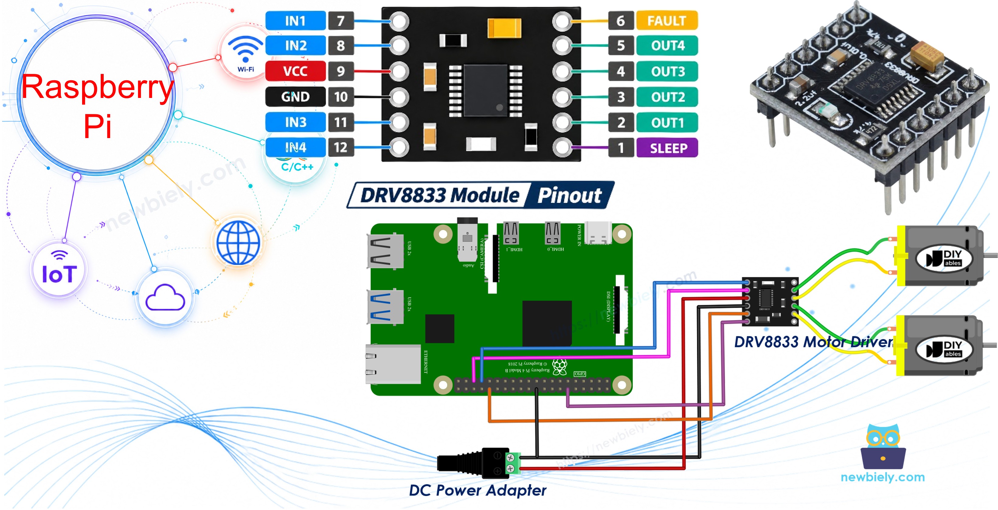
A Raspberry Pi GPIO pin gives only a few milliamps at 3.3V, which is nowhere near enough to spin a motor. The DRV8833 is a tiny board that sits between the Pi and the motors and does the heavy lifting. It handles two brushed DC motors at once, which makes it a nice fit for small battery-powered robot cars. This tutorial instructs you how to use Raspberry Pi with the DRV8833 motor driver. In detail, we will learn:
- What the DRV8833 module is and what each of its pins does
- How the two input pins of a channel decide forward, reverse, coast and brake
- How to wire one DC motor and write a Python script that changes its speed and direction
- How to wire two DC motors and drive them like the wheels of a robot car
We suggest:
- Reading the Raspberry Pi - DC Motor tutorial if you have an L298N driver and a 12V motor instead.
Hardware Preparation
Or you can buy the following kits:
| 1 | × | DIYables Sensor Kit (18 sensors/displays) |
Additionally, some of these links are for products from our own brand, DIYables .
You need only one DC motor for Part 1. The second motor is used in Part 2.
Overview of DRV8833 Motor Driver
The DRV8833 is a dual H-bridge chip from Texas Instruments. Each H-bridge can push current through a motor in either direction, so one module runs two DC motors on their own (it can also drive one small bipolar stepper motor, but that is not covered here). Its switches are MOSFETs with low on-resistance (about 360 mΩ), so it loses much less voltage and runs cooler than the older L298N. That is a big plus when your motors run from a 3V to 9V battery pack.
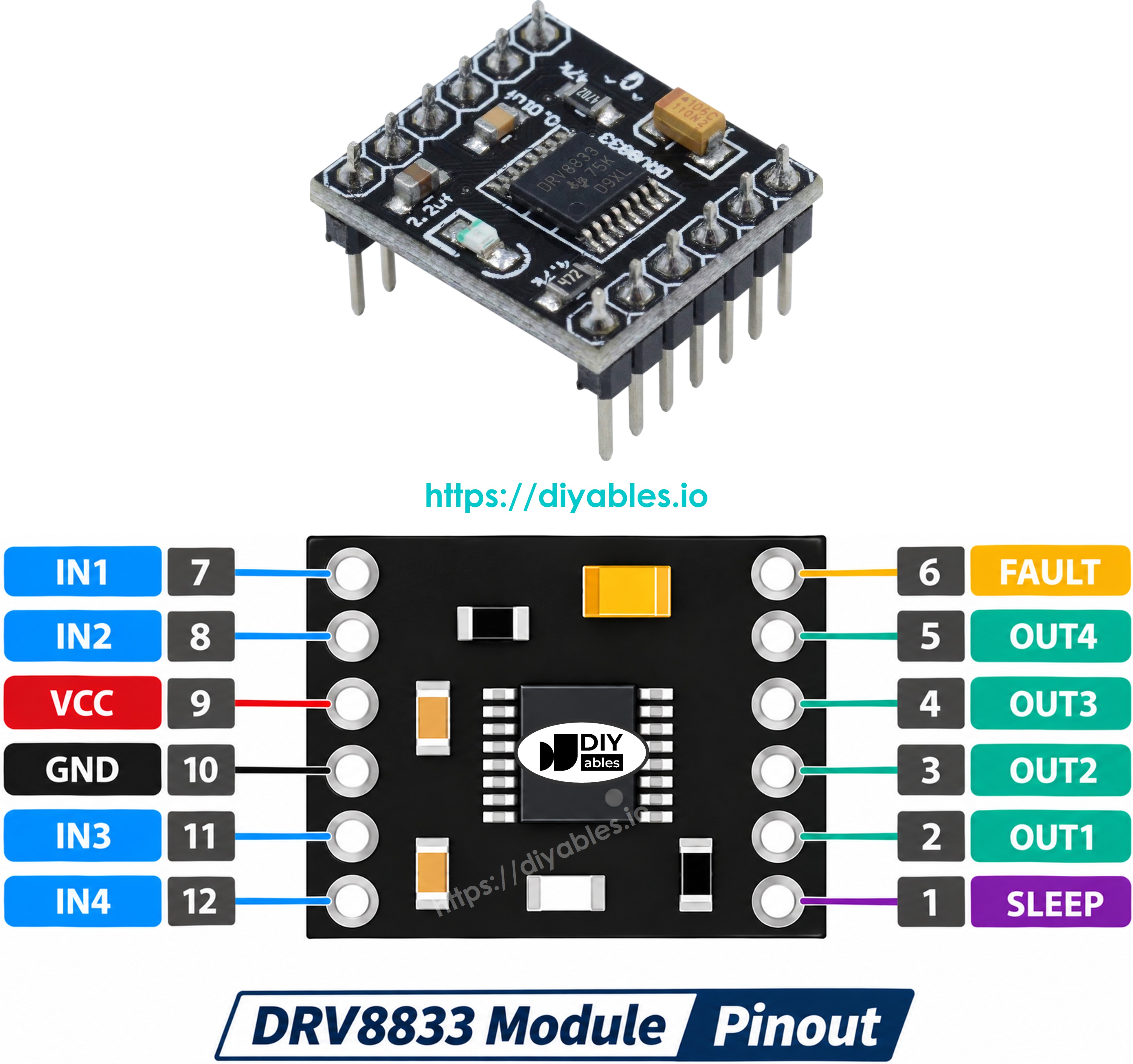
The module has the following pins (the labels vary between makers, for example AIN1/AIN2/BIN1/BIN2, AOUT1/AOUT2, SLP and FLT):
- VCC: This pin must be connected to the positive side of the motor power supply (2.7V to 10.8V)
- GND: This pin must be connected to ground (0V). The ground of the motor supply and the ground of Raspberry Pi both go here
- IN1, IN2: control inputs for motor A
- IN3, IN4: control inputs for motor B
- OUT1, OUT2: the two wires of motor A are connected here
- OUT3, OUT4: the two wires of motor B are connected here
- EEP (nSLEEP): the enable pin. It must be HIGH for the driver to work. If it is LOW, the chip goes to sleep and the motors do not move
- ULT (nFAULT): an optional fault output. It goes LOW on over-current, over-heating or too-low supply voltage. You can leave it unconnected
※ NOTE THAT:
The arrangement of pins on a module can differ between manufacturers. It is essential to always use the labels printed on the module when working with it. Be sure to take a close look!
Some facts that are good to know:
- There is no separate logic power pin. The chip makes its own logic voltage inside, so the 3.3V GPIO signals of Raspberry Pi work directly
- Each channel can deliver about 1.5A continuous and 2A peak (with good cooling)
- It has built-in protection: under-voltage lockout, over-current and thermal shutdown
- PWM signals up to 50 kHz are accepted on the input pins
How Speed and Direction Are Controlled
Unlike the L298N, the DRV8833 has no ENA/ENB speed pin. Both the direction and the speed come from the two input pins of a channel. Here is what motor A does for each combination of IN1 and IN2 (motor B works the same way with IN3 and IN4):
| IN1 pin | IN2 pin | Motor A |
|---|---|---|
| LOW | LOW | Coast (the motor spins freely and slowly stops) |
| HIGH | LOW | Forward |
| LOW | HIGH | Reverse |
| HIGH | HIGH | Brake (the motor stops quickly) |
To change the speed, we send a PWM signal to one input and keep the other LOW:
- Forward at a given speed: PWM on IN1, IN2 LOW
- Reverse at a given speed: IN1 LOW, PWM on IN2
This means both input pins of a channel need PWM. On Raspberry Pi, the RPi.GPIO library can make a software PWM signal on any GPIO pin, with a duty cycle from 0 to 100. A duty cycle of 0 is the same as LOW, and 100 is the same as HIGH. The pins used in this tutorial (GPIO12, GPIO13, GPIO18 and GPIO19) are also the hardware-PWM pins of Raspberry Pi, but the scripts here use software PWM.
Powering the Motors
The motors get their power from the 5V power adapter through the DC power jack, connected to the VCC and GND pins of the DRV8833. A 4 x AA battery pack (about 6V) works too.
※ NOTE THAT:
- Never power the motors from the 5V or 3.3V pin of Raspberry Pi. A motor pulls a big current when it starts, and this can make the Pi reboot or even damage it.
- The ground of the power adapter, the DRV8833 and Raspberry Pi must be connected together. Without a common ground, the control signals have no reference and the motor will not respond correctly.
Part 1 - Control One DC Motor with DRV8833
In this part, we use channel B of the DRV8833: the motor is connected to OUT3 and OUT4, and it is driven by IN3 and IN4.
Wiring Diagram
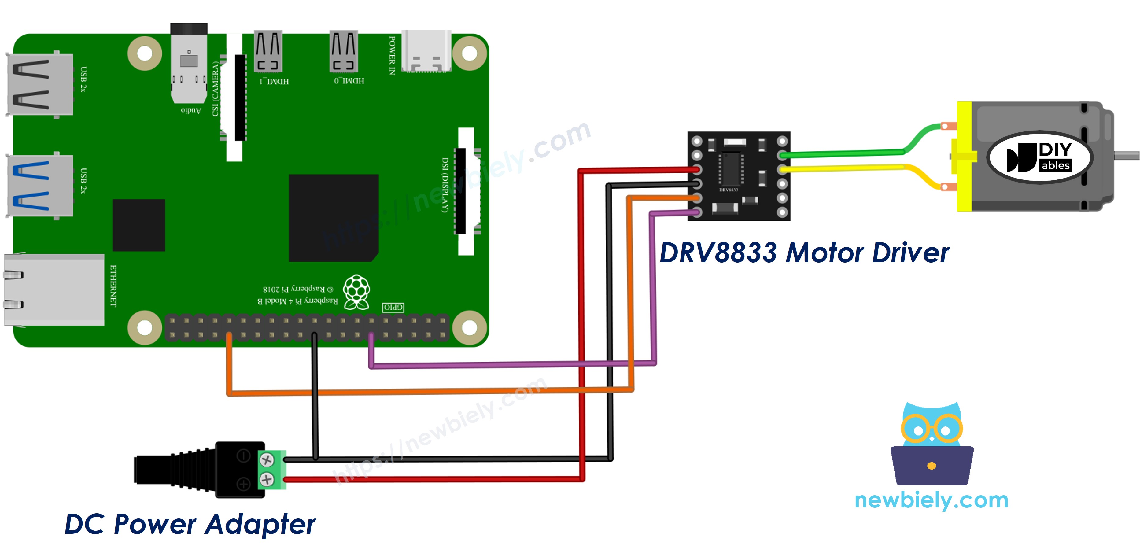
This image is created using Fritzing. Click to enlarge image
Connect the components as follows:
- DRV8833 IN3 pin to Raspberry Pi GPIO 12 (pin 32)
- DRV8833 IN4 pin to Raspberry Pi GPIO 18 (pin 12)
- DRV8833 EEP pin to Raspberry Pi 3.3V (pin 1), so the driver is always awake
- DRV8833 GND pin to Raspberry Pi GND (pin 6) and to the negative terminal of the DC power jack
- DRV8833 VCC pin to the positive terminal of the DC power jack (5V adapter)
- DRV8833 OUT3 and OUT4 pins to the two wires of the DC motor
- DRV8833 ULT pin: not connected
How To Program for Raspberry Pi to Control One DC Motor
The script below runs the motor through a repeating cycle:
- Forward, with the speed going up slowly from 0 to 100%
- Full speed forward for 2 seconds
- Coast for 2 seconds
- Reverse at 60% speed for 2 seconds
- Brake for 2 seconds
The helper function motor_b(speed) takes a signed speed from -100 to 100. A positive value turns the motor forward, a negative value turns it in reverse, and 0 lets it coast.
Detailed Instructions
- Make sure you have Raspbian or any other Raspberry Pi compatible operating system installed on your Pi.
- Make sure your Raspberry Pi is connected to the same local network as your PC.
- Make sure your Raspberry Pi is connected to the internet if you need to install some libraries.
- If this is the first time you use Raspberry Pi, See how to set up the Raspberry Pi
- Connect your PC to the Raspberry Pi via SSH using the built-in SSH client on Linux and macOS or PuTTY on Windows. See to how connect your PC to Raspberry Pi via SSH.
- Make sure you have the RPi.GPIO library installed. If not, install it using the following command:
- Create a Python script file drv8833_one_motor.py and add the following code:
- Plug the 5V power adapter into the DC power jack.
- Save the file and run the Python script by executing the following command in the terminal:
- Watch the motor and check the terminal:
You will hear the motor speed up, run at full speed, roll down to a stop, spin the other way, and then stop sharply. If the motor turns the wrong way when the terminal says "Forward", swap the two motor wires on OUT3 and OUT4.
The script runs in an infinite loop continuously until you press Ctrl + C in the terminal. When it stops, the finally block turns off PWM and resets the GPIO pins, so the motor does not keep running.
Part 2 - Control Two DC Motors with DRV8833
Now let's use both channels. Think of motor A as the left wheel and motor B as the right wheel of a small robot car.
Wiring Diagram
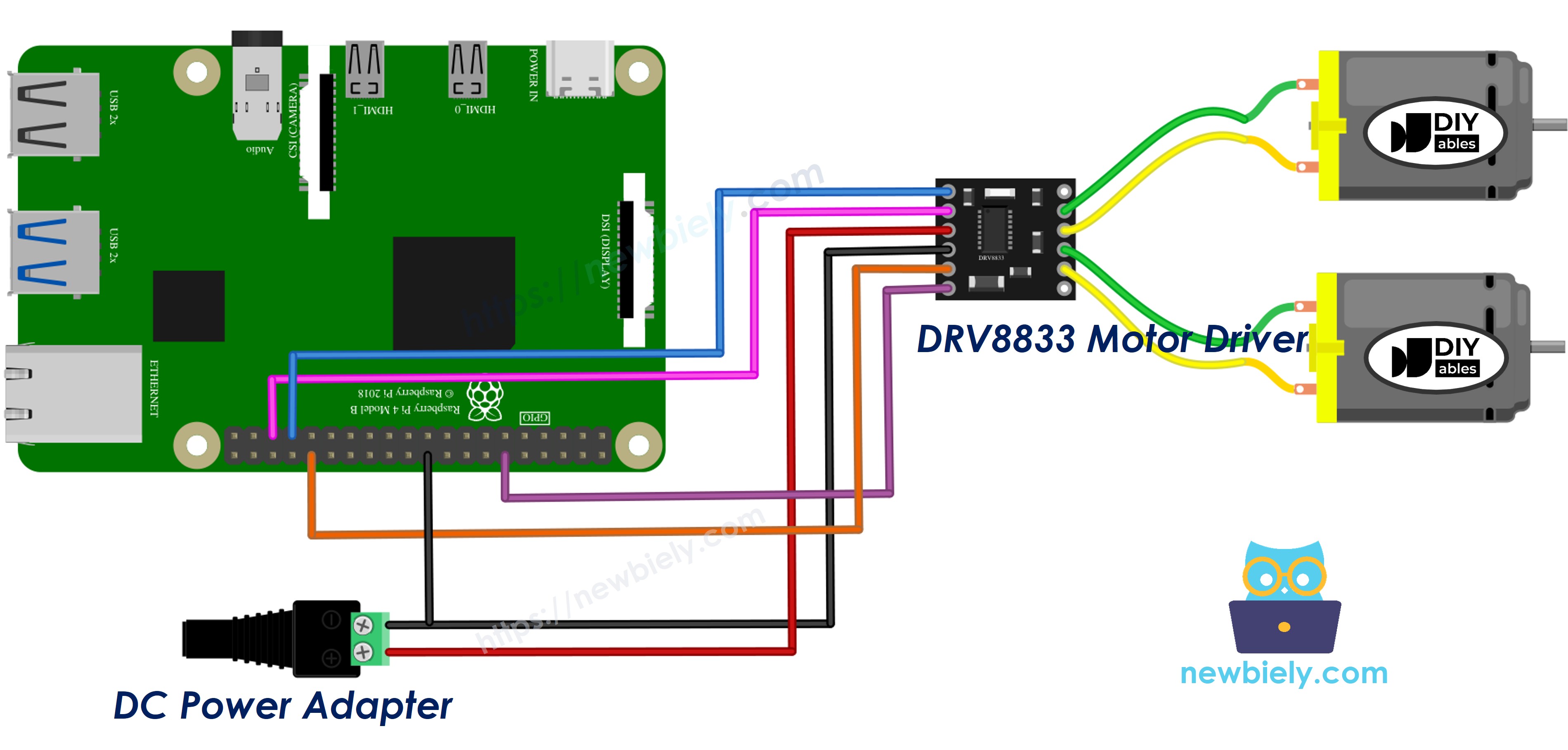
This image is created using Fritzing. Click to enlarge image
To simplify and organize your wiring setup, we recommend using a Screw Terminal Block Shield for Raspberry Pi. This shield ensures more secure and manageable connections, as shown below:
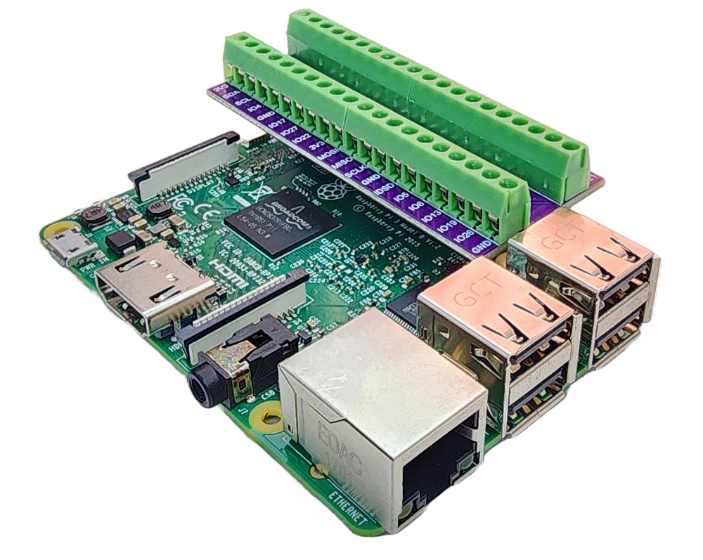
Keep all the wires from Part 1 (motor B on OUT3/OUT4, IN3 and IN4), then add:
- DRV8833 IN1 pin to Raspberry Pi GPIO 13 (pin 33)
- DRV8833 IN2 pin to Raspberry Pi GPIO 19 (pin 35)
- DRV8833 OUT1 and OUT2 pins to the two wires of the second DC motor (motor A)
Both motors now share the same power adapter, so make sure it can deliver enough current for two motors at the same time.
How To Program for Raspberry Pi to Control Two DC Motors
The script uses motor_a(speed) and motor_b(speed), both with a signed speed from -100 to 100. A small drive() function prints the action name, sets both motors and waits. The car moves through this cycle:
- Forward: both motors forward
- Backward: both motors in reverse
- Turn left: motor A in reverse, motor B forward
- Turn right: motor A forward, motor B in reverse
- Stop: both motors coast
Detailed Instructions
- Create a Python script file drv8833_two_motors.py and add the following code:
- Save the file and run the Python script by executing the following command in the terminal:
- Check the terminal output:
If one wheel spins the opposite way from the other while "Moving forward" is printed, swap the wires of that motor on its OUT pins.
You can tune DRIVE_SPEED and TURN_SPEED at the top of the script. Small motors often need at least 30 to 40% duty cycle to start moving at all.
Additional Knowledge
Let's compare the DRV8833 with the L298N, which is used in the Raspberry Pi - DC Motor tutorial:
| DRV8833 | L298N | |
|---|---|---|
| Motor supply voltage | 2.7V to 10.8V | 5V to 35V |
| Current per channel | about 1.5A (2A peak) | about 2A |
| Switch type | MOSFET (low voltage drop) | Bipolar transistor (about 2V drop or more) |
| Speed control | PWM on IN pins | PWM on ENA/ENB pins |
| Logic supply | not needed | 5V pin |
| Size | very small | large, with heatsink |
In short, the DRV8833 is the better choice for small 3V to 9V motors and battery robots, because more of the battery voltage reaches the motors. The L298N is the choice when the motors need 12V or more.
If one motor needs more current, the two channels of the DRV8833 can be connected in parallel to give about 3A. This is an advanced setup and is not needed for small 5V motors.