
Raspberry Pi - PC817 Optocoupler: Monitor 12V/24V DC Input Signal
The GPIO pins of a Raspberry Pi work at 3.3V and they are NOT 5V tolerant, so a stray 12V or 24V wire touching the 40-pin header does not just damage one pin - it usually kills the whole board, including the SD card slot, the Ethernet port and everything else on it. A PC817 optocoupler removes that risk completely: the external voltage never reaches the Pi, because the signal crosses the gap as light instead of electricity.
Most people who wire one of these up are really asking one plain question: is that machine, pump, heater or lamp actually running right now? A Raspberry Pi is a good answer to it, because it can be left switched on for weeks and can write down what it saw. This tutorial shows how to turn a Raspberry Pi into an always-on node that watches an isolated 12V or 24V line and keeps a record of it. In detail, we will learn:
- Why an optocoupler is the safest way to read a 12V/24V signal with a Raspberry Pi
- Which of the three PC817 module variants - 3-5V, 12V or 24V - matches the line you want to watch
- How to wire a ready-made PC817 isolation module to the Raspberry Pi, and how to build the same thing from the bare chip if you prefer
- How to find out in under a minute whether your module is active-LOW or active-HIGH, and how to flip the code with one constant
- How to tap the PC817 across a device, in parallel with it, so that the Pi follows whether that device is on or off
- How to program the Raspberry Pi in Python to read the isolated input
- How to log every change of the external signal to a file with a timestamp, so you end up with a run-time record
We suggest:
- Reading the Raspberry Pi - Button tutorial first if you have never configured a GPIO pin as a pull-up input. The PC817 is read in exactly the same way.
- Reading the Raspberry Pi - Limit Switch tutorial instead if the thing you want to detect is a dry mechanical contact that carries no voltage at all. In that case no optocoupler is needed.
- Reading the Raspberry Pi - Log Data with Timestamp to SD Card tutorial if you plan to leave the Pi running as a long-term logging node.
- Reading the Raspberry Pi - Relay tutorial if you want to switch a 12V/24V load rather than read one. A relay is the output-side counterpart of the optocoupler.
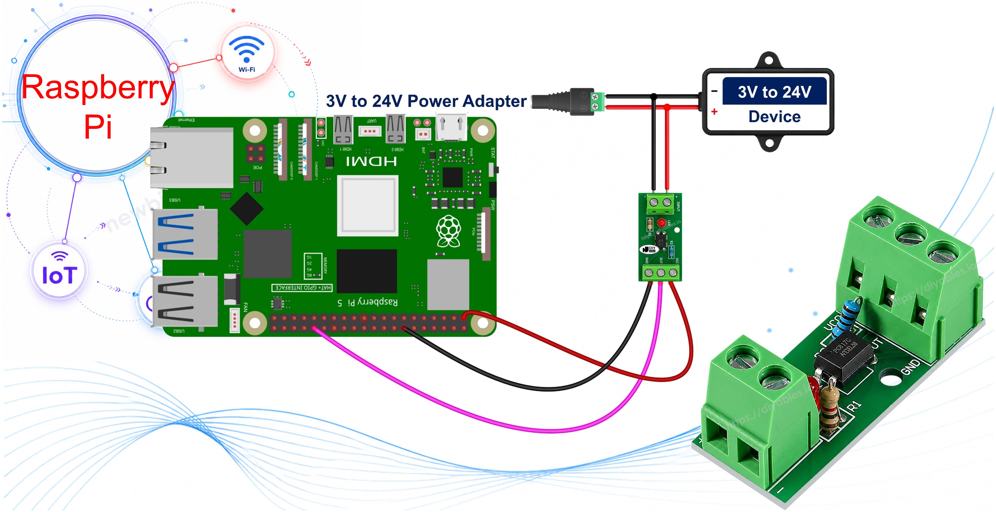
Hardware Preparation
Or you can buy the following kits:
| 1 | × | DIYables Sensor Kit (18 sensors/displays) |
Additionally, some of these links are for products from our own brand, DIYables .
The module variants are the same board sold in different flavours - you buy the one that matches your signal, not more than one.
Overview of PC817 Optocoupler
The PC817 is a photocoupler, also called an opto-isolator or optocoupler. Inside its small black package there is an infrared LED facing a phototransistor across an insulating gap. When current flows through the LED, its light switches the phototransistor on. Because the only thing crossing the gap is light, the two sides of the chip stay electrically separate - which is exactly what protects the Raspberry Pi.
The specifications of the PC817 are:
- Package: 4-pin DIP, with pin 1 marked by a dot or a notch
- Input LED forward voltage (Vf): about 1.2 V typical, 1.4 V maximum
- Input LED forward current (If): 20 mA continuous maximum, 5 mA to 20 mA in normal use, 10 mA is a good target
- Output collector-emitter voltage (VCEO): 35 V maximum
- Output collector current (IC): 50 mA maximum
- Collector power dissipation: 150 mW
- Isolation voltage: 5000 Vrms for 1 minute
- Current Transfer Ratio (CTR): 50% to 600% depending on the rank (rank A 80-160%, rank B 130-260%, rank C 200-400%, rank D 300-600%)
- Switching speed: rise time about 4 us, fall time about 3 us
- Operating temperature: -30 °C to +100 °C
The 5000 Vrms isolation figure is the number that matters for a Raspberry Pi. It means the 12V or 24V circuit would have to break through five thousand volts of insulation before it could reach the header.
The PC817 Optocoupler Isolation Module
The practical way to use a PC817 with a Raspberry Pi is a ready-made isolation module. It carries the same chip on a small board together with a series resistor, a status LED and screw terminals, so nothing has to be calculated or soldered:
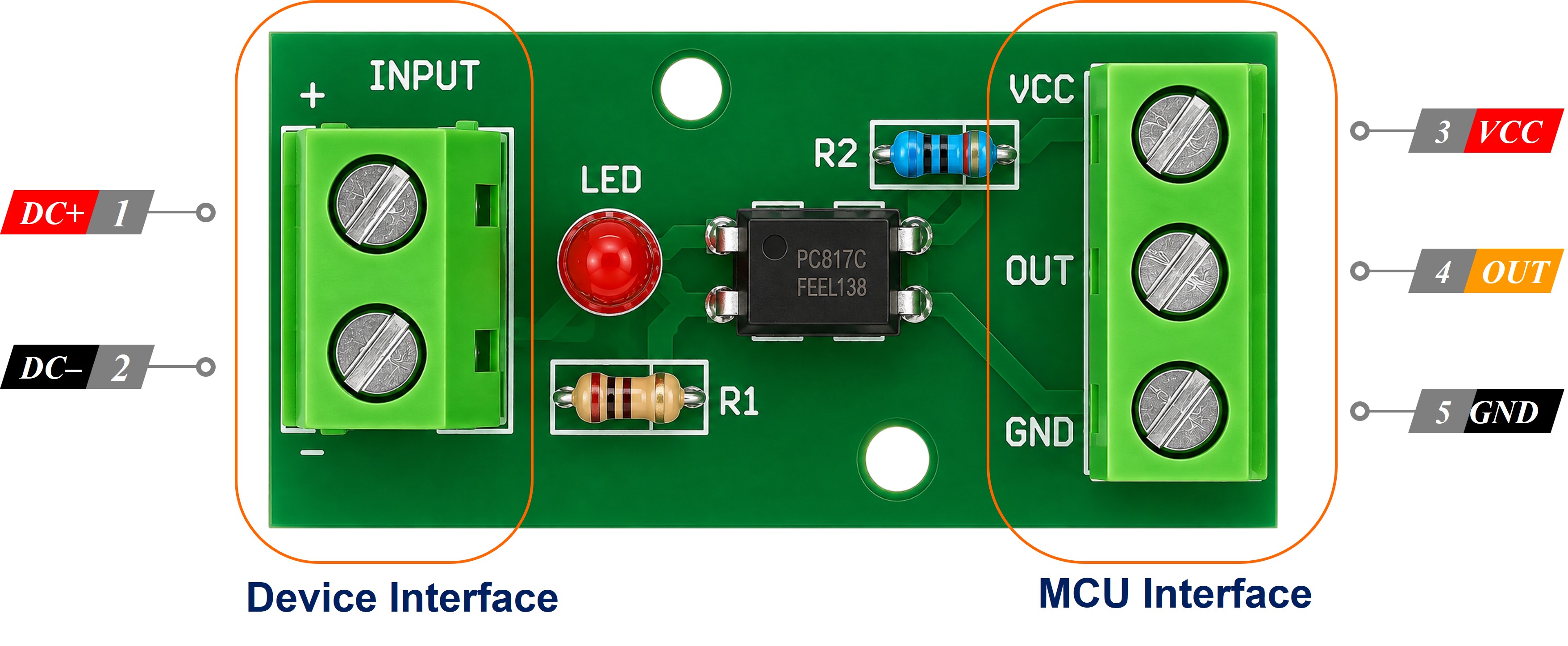
- IN+ and IN- screw terminals: the input side. The 12V/24V signal must be connected to IN+ and the ground of that same 12V/24V circuit must be connected to IN-.
- VCC pin: must be connected to the 3.3V (pin 1) of the Raspberry Pi.
- GND pin: must be connected to a ground pin of the Raspberry Pi, for example GND (pin 6).
- OUT pin (sometimes labelled DO or OUT1): must be connected to a GPIO pin of the Raspberry Pi, for example GPIO 12 (pin 32).
The status LED on the board is worth knowing about before you wire anything: it lights when the input side is energised, so it tells you the input half is working even before the Raspberry Pi is switched on.
※ NOTE THAT:
The arrangement of the pins on a module can differ between manufacturers. Some boards swap VCC and GND, and some print the input terminals as + and - instead of IN+ and IN-. Always trust the labels printed on your own module rather than the picture above, and look closely before powering anything.
Which Optocoupler Module Do I Need - 3-5V, 12V or 24V?
This is the one purchase decision on the whole page, and it is easy to get wrong because all three variants look identical. The series resistor is already fitted on the board, and it is sized for ONE input voltage. That is why the modules are sold as three separate versions:
| The line you want to watch | The module to buy | Typical example |
|---|---|---|
| A 3.3V or 5V logic signal | the 3-5V module | a sensor output, a 5V PLC signal, another microcontroller |
| A 12V DC signal | the 12V module | an automotive circuit, a 12V pump or fan, an alarm panel |
| A 24V DC signal | the 24V module | an industrial machine output, a UPS alarm contact, a 24V solenoid |
Two mistakes to avoid, because they cost either a module or an afternoon:
- Feeding a 12V module from a 24V line pushes roughly double the intended current through its internal LED and will damage it.
- Feeding a 24V module from a 12V line underdrives the LED, so the output may switch late, switch unreliably, or not switch at all - and an intermittent input is far harder to diagnose than a dead one.
If your signal sits between the listed voltages, or you are not sure what it is, measure it with a multimeter before ordering. On a module you do not calculate anything, you choose the right variant - and that choice is the module equivalent of picking the resistor value by hand.
The 3-5V variant surprises some people: why isolate a signal that a GPIO pin could read directly? Because isolation is about breaking the ground path, not only about high voltage. It earns its place whenever the two circuits run from separate power supplies, sit at opposite ends of a long cable, or one of them is electrically noisy - a motor driver, or the low-voltage control board inside a mains-powered appliance. With a Raspberry Pi that argument is stronger than usual, because the thing you are protecting is a whole Linux computer with an SD card in it.
How It Works
The GPIO pin of the Raspberry Pi is configured as an input with the internal pull-up enabled, so it sits at 3.3V whenever nothing pulls it down. The phototransistor is what pulls it down.
| External 12V/24V signal | Internal LED | Phototransistor | Raspberry Pi GPIO reading |
|---|---|---|---|
| PRESENT | on | conducting | LOW |
| ABSENT | off | not conducting | HIGH |
So the reading is INVERTED: the pin reads LOW when the external signal is present, and HIGH when it is absent. This surprises almost everyone the first time. The code on this page inverts it back, so that a variable named signal_active is True when the 12V/24V line really is live.
The Raspberry Pi has software-selectable internal pull-up resistors on its GPIO pins, so no external pull-up resistor has to be added. It is enabled with one argument in GPIO.setup().
Is Your Optocoupler Module Active-LOW or Active-HIGH?
The table above is settled physics for the bare chip wired as this page describes: with a pull-up on the GPIO pin, the phototransistor pulls the pin down, so signal present = LOW.
A module is a different matter. Some manufacturers add an inverting stage on the board, so the OUT pin follows the input instead of opposing it. Both kinds are on sale, they look the same, and the seller listing rarely says which one you have got. So do not assume - spend a minute finding out:
- Wire the module to the Raspberry Pi as shown below and run the first script on this page, which reports the raw state of the pin.
- With nothing connected to the input screw terminals, note what the terminal prints.
- Now energise the input side and note what it prints instead.
- Whatever appears while the signal is present is your module's active level. If the pin is reading LOW there, the module is active-LOW; if it is reading HIGH, the module is active-HIGH.
- Cross-check it against the on-board status LED: that LED lights when the input side is energised, so the LED coming on and the pin reaching its active level should always happen together. If the LED lights and nothing at all changes on the Pi, the problem is on the output side - VCC, GND or the OUT wire - not on the input side.
Whichever way yours turns out, the fix is one word in the code. Both Python scripts on this page start with:
MODULE_ACTIVE_LOW = True
Leave it as True for an active-LOW module, set it to False for an active-HIGH one. Nothing else in either script has to change, because every reading is derived from that single constant.
Wiring Diagram
Wiring a PC817 optocoupler isolation module to the Raspberry Pi
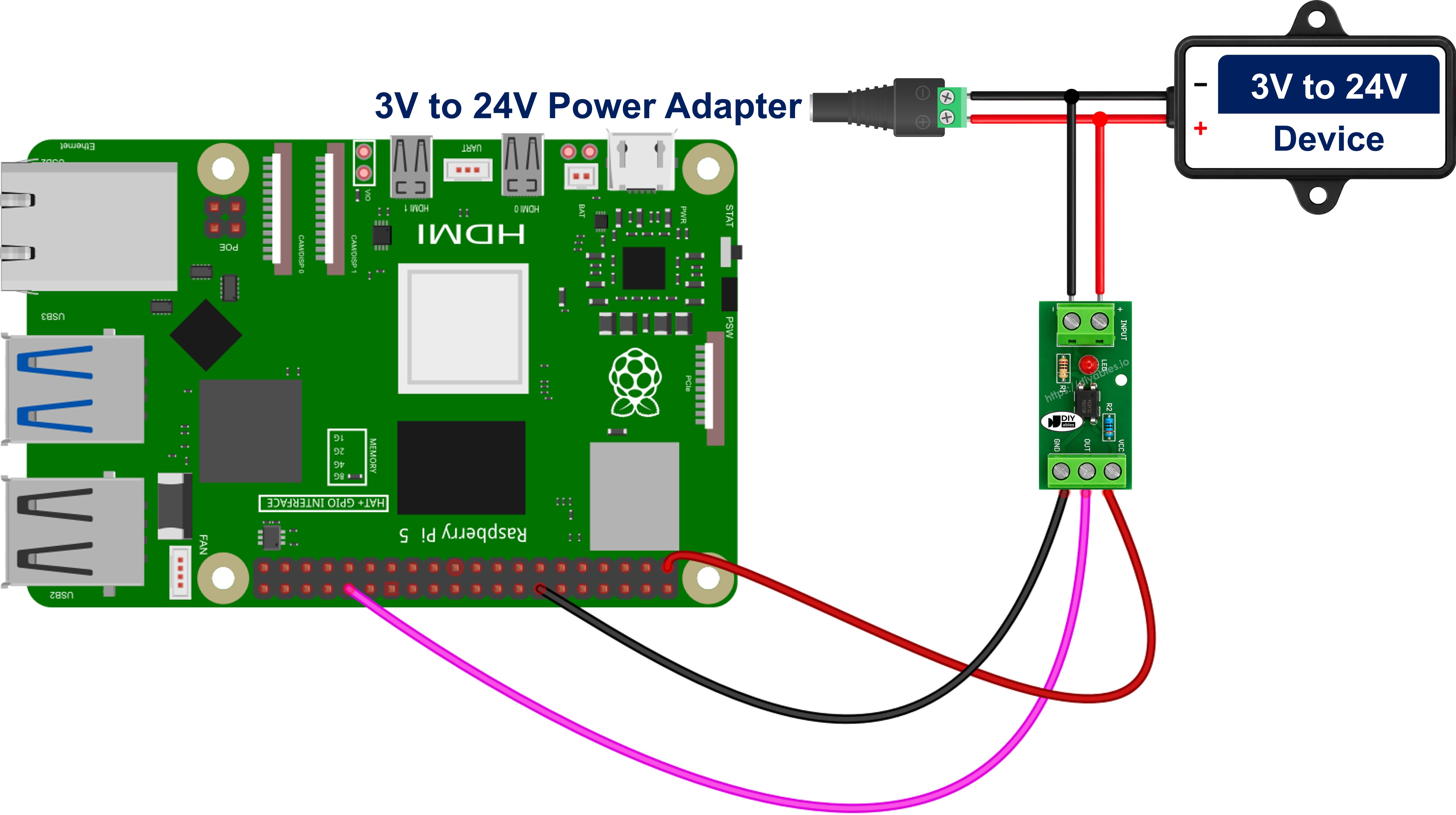
This image is created using Fritzing. Click to enlarge image
To simplify and organize your wiring setup, we recommend using a Screw Terminal Block Shield for Raspberry Pi. This shield ensures more secure and manageable connections, as shown below:
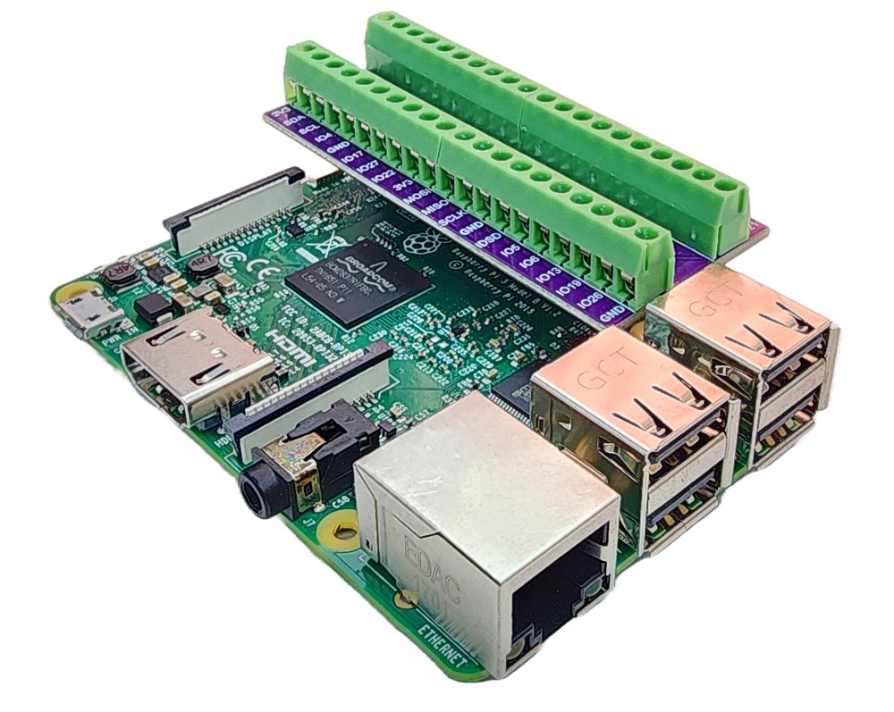
The connections are:
- The positive wire of the external 12V/24V signal to the IN+ screw terminal of the module
- The ground of the external 12V/24V circuit to the IN- screw terminal of the module
- The VCC pin of the module to 3.3V (pin 1) of the Raspberry Pi
- The GND pin of the module to GND (pin 6) of the Raspberry Pi
- The OUT pin of the module to GPIO 12 (pin 32) of the Raspberry Pi
There is no series resistor anywhere in that list, and that is the whole point of a module - as long as the variant matches the voltage arriving at the input terminals, the resistor is already on the board.
※ NOTE THAT:
Power the output side of the optocoupler from the 3.3V (pin 1 or pin 17) of the Raspberry Pi, NOT from the 5V (pin 2 or pin 4). A GPIO pin is only rated for 3.3V, and a module powered from 5V can present 5V on its OUT pin.
※ NOTE THAT:
The ground of the 12V/24V circuit must NOT be connected to the ground of the Raspberry Pi. Those two grounds must stay apart - that separation is the entire reason the PC817 is there. If the two grounds are tied together the circuit still switches and the code still works, but the isolation is gone and the Raspberry Pi is once again exposed to whatever happens on the 12V/24V side.
Optional - Building the Same Input From the Bare PC817 Chip
If you would rather solder it yourself, the bare chip does the same job for less money - you simply take back the resistor decision that the module made for you.
The chip is a 4-pin DIP, with pin 1 marked by a dot or a notch and the pins numbered anticlockwise from there.
The connections are:
- The positive wire of the external 12V/24V signal to one leg of the series resistor
- The other leg of the series resistor to PC817 pin 1 - Anode (A)
- PC817 pin 2 - Cathode (K) to the ground of the external 12V/24V circuit, NOT to the ground of the Raspberry Pi
- PC817 pin 4 - Collector (C) to GPIO 12 (pin 32) of the Raspberry Pi
- PC817 pin 3 - Emitter (E) to GND (pin 6) of the Raspberry Pi
Pins 1 and 2 are the input side, pins 3 and 4 the output side, with no electrical path between them. Size the resistor with R = (Vin - 1.2) / 0.01 for a target LED current of 10 mA: 220 Ω at 3.3V, 390 Ω at 5V, 1 kΩ at 12V, 2.2 kΩ at 24V (a 1/2 W part at 24V). Leaving a 1 kΩ resistor in place on a 24V line pushes about 22.8 mA through an LED rated for 20 mA - the bare-chip version of fitting a 12V module to a 24V line. A bare chip wired this way is always active-LOW.
Connecting the PC817 in parallel with the device you want to monitor
The diagrams above show the input fed from a supply of its own, which is what you would do on a bench. On a real installation the input side is not fed by anything of its own at all - it is tapped ACROSS the device whose state you want to know, in parallel with it. The example used here is the 24V alarm contact of a machine or a UPS, the kind of line that is already wired to a beacon or a panel and that you now want the Raspberry Pi to watch as well.
WARNING
Never put the optocoupler input in SERIES with the device. In series, the entire load current of that device - a relay coil, a contactor, a lamp, a motor - is forced through the internal LED, and the LED is destroyed the moment the device is switched on. The input goes in parallel, across the two terminals of the device, and nothing in the existing circuit is cut or rerouted.
Taking that 24V machine or UPS alarm contact as the example, and using a 24V module for it, the connections are:
- The positive (switched) terminal of the 24V alarm contact to the IN+ screw terminal of the module
- The negative (return) terminal of the 24V alarm contact to the IN- screw terminal of the module
- The VCC pin of the module to 3.3V (pin 1) of the Raspberry Pi
- The GND pin of the module to GND (pin 6) of the Raspberry Pi
- The OUT pin of the module to GPIO 12 (pin 32) of the Raspberry Pi
- The existing wiring of the alarm contact stays exactly as it was - nothing is disconnected
A parallel tap on a module needs no series resistor of its own; the one on the board is already sized for 24V, which is precisely why the variant has to match the line you are tapping. On the bare-chip route the same tap gets a 2.2 kΩ resistor in front of pin 1.
The tap draws about 10 mA. Beside what a relay coil, a lamp, a solenoid valve or a motor draws that is nothing at all, so the device carries on working exactly as before. The measurement is non-invasive and read-only.
Polarity matters, because the input side is an LED and an LED conducts in one direction only. Swap IN+ and IN- - or pin 1 and pin 2 on a bare chip - and the circuit will simply never turn on, with no other symptom to go on. Check which side of the tap is positive before wiring it.
※ NOTE THAT:
An inductive device needs a clamp diode. A relay coil, a solenoid, a contactor, a valve or a motor throws out a large reverse-voltage spike the moment it switches off, and the PC817 input LED is rated for only 6 V in reverse, so that spike can kill it. Fit an ordinary diode in reverse-parallel directly across the input terminals - diode cathode to IN+, diode anode to IN- (on a bare chip, cathode to pin 1 and anode to pin 2). In normal operation that diode is reverse-biased and does nothing at all; on a spike it conducts and clamps the reverse voltage to well under a volt. A 1N4148 suits a small tap, a 1N4007 a heavier one.
Some solid-state outputs leak. PLC transistor outputs, triac outputs and LED-lamp drivers can pass a small current even while they are switched off, and enough of that leakage partially lights the internal LED - at which point the Raspberry Pi reports the device as ON while it is actually sitting idle. The symptom is easy to recognise: the reading never returns to inactive, and on a module the status LED glows faintly instead of going out. The cure is a bleeder resistor of about 4.7 kΩ to 10 kΩ fitted in parallel with the optocoupler input terminals, so that the leakage flows through the resistor instead of through the LED.
This is also a DC-only tap: the PC817 input is a single LED and responds to one polarity only, so it is the wrong part for sensing an AC line - that needs an optocoupler whose input stage carries two back-to-back LEDs.
Because the tap sits across the device rather than in front of it, what the Raspberry Pi reads is the real state of that device, no matter what caused it - a thermostat, a float switch, a PLC, a timer, or somebody pressing a button at the other end of the building. It follows the device just as faithfully when the device fails to come on at all, which is what makes this worth logging: run-time totals, fault alerts and "did it actually start?" checks all fall out of the same tap. One honest limitation: this tells you the device is energised, not that it is doing its job. A seized motor or a burnt-out heater still draws power and will still read as ON.
Raspberry Pi Code - Reading an Isolated 12V/24V Signal Through the PC817 Optocoupler
No library is required for this project. The PC817 turns the external voltage into a plain HIGH/LOW level, so RPi.GPIO alone is enough.
Detailed Instructions
- Wire the PC817 to your Raspberry Pi as shown in the module wiring diagram above, and double-check that the 12V/24V ground is not touching the Pi.
- Make sure you have Raspberry Pi OS or any other Raspberry Pi compatible operating system installed on your Pi.
- Make sure your Raspberry Pi is connected to the same local network as your PC.
- Make sure your Raspberry Pi is connected to the internet if you need to install some libraries.
- If this is the first time you use Raspberry Pi, See how to set up the Raspberry Pi
- Connect your PC to the Raspberry Pi via SSH using the built-in SSH client on Linux and macOS or PuTTY on Windows.
- Make sure you have the RPi.GPIO library installed. If not, install it using the following command:
- Create a Python script file pc817_optocoupler.py and add the following code:
- Save the file and run the Python script by executing the following command in the terminal:
- Energise the external 12V/24V line, then switch it off again.
- Check the result in the Terminal.
The script keeps polling the GPIO pin every half a second and prints one line each time, forever. It stops only when you press Ctrl + C in the terminal, which also releases the GPIO pin.
This is also the script to run for the active-LOW or active-HIGH check described earlier: energise the input and see which label appears. If it prints ENERGISED while the line is idle and idle while the line is live, your module inverts on-board - set MODULE_ACTIVE_LOW to False at the top of the file and run it again. Nothing else in the script decides which way round the reading goes, so that single constant is the only thing to change.
Code Explanation
Check out the line-by-line explanation contained in the comments of the source code!
Raspberry Pi Code - Monitoring Whether a Device Is On or Off and Logging It with a Timestamp
Printing the same line twice a second is useful for a first test, but a Raspberry Pi is usually left running as a small always-on server. In that role you do not want a stream of identical lines - you want a record of the moments when something actually changed. This second script prints and appends one line to a file only when the isolated input changes state, together with how long the previous state lasted.
That makes it directly usable for a 24V machine running or fault lamp line, and for a 12V freezer compressor or sump-pump run signal, where the interesting question is not the state right now but how often and for how long the thing ran overnight. Left running for weeks - under nohup, or as a small systemd service - the same script quietly builds a run-hour record of the device, and the gap between two entries answers the question that a glance at a panel never can: did it actually start when it was supposed to?
Settle the polarity question with the first script BEFORE you walk away and leave this one running, because a module wired the other way round does not fail loudly here - it quietly writes a plausible but inverted history into the log file, every run recorded as an idle period and every idle period as a run, and you may not notice for weeks.
Detailed Instructions
- Create a Python script file pc817_optocoupler_logger.py and add the following code:
- Save the file and run the Python script by executing the following command in the terminal:
- Switch the external 12V/24V line on and off a few times, leaving it in each state for a while.
- Check the result in the Terminal.
The same lines are appended to a file named isolated_input.log next to the script, so the history survives after you close the SSH session. This script carries the same MODULE_ACTIVE_LOW constant as the first one and derives its change detection from it, so whatever you settled on there holds here too. The script keeps polling on its own loop interval until you press Ctrl + C in the terminal.
Code Explanation
Check out the line-by-line explanation contained in the comments of the source code!
Video Tutorial
Challenge Yourself
- Easy: change the printed labels to match your own machine, and light an LED on another GPIO pin whenever the isolated input is live.
- Medium: turn the second script into a run-hour counter for the monitored device: add up the time it spent live, count how many times it started, and print both totals on every change.
- Advanced: add software debouncing so that a noisy long-run 24V wire cannot register two events in a row, watch four isolated lines at once with a 4-channel optocoupler module, or write a "the pump did not start" warning into the log when the input has still not gone live a few minutes after you expected it to.
Additional Knowledge
A very common beginner question is why a couple of resistors would not do the same job for much less money.
Let's compare a PC817 optocoupler with a resistor voltage divider for reading a 24V signal on a Raspberry Pi.
The commons between the optocoupler and the voltage divider:
- Both bring a 24V signal down to something a 3.3V GPIO pin can accept.
- Both are read with the same single line of Python.
- Both cost very little.
The differences between the optocoupler and the voltage divider:
| PC817 optocoupler | Resistor voltage divider | |
|---|---|---|
| Electrical connection to the Pi | none, the two sides are separate | direct, the two circuits share a ground |
| Isolation voltage | 5000 Vrms | none |
| If the 24V side spikes or shorts | the Pi is unaffected | the spike reaches the GPIO pin |
| Reading | inverted on the bare chip and on most modules, set by one constant in the code | not inverted, HIGH means signal present |
| Ground handling | the 12V/24V ground must stay separate | the 12V/24V ground must be tied to the Pi ground |
| Extra parts | one module, or one chip and one resistor | two resistors |
For an experiment on your desk with a bench supply you control, a divider is acceptable. For anything attached to a vehicle, a machine, an alarm panel or a mains-powered 24V supply, the divider is a bad trade: it saves one component and gives away the only thing standing between an electrical fault and a dead Raspberry Pi. Because a damaged GPIO pin normally means replacing the whole board rather than a single chip, the optocoupler pays for itself the first time something goes wrong.