
Arduino UNO Q - Multi-Function Shield
Want to experiment with multiple components at once on your Arduino UNO Q? This beginner-friendly tutorial shows you how to use the Multi-Function Shield with Arduino UNO Q — step by step.
In this tutorial, you will learn:
- What the Multi-Function Shield includes and how it works
- How to connect the Multi-Function Shield to Arduino UNO Q
- How to program the MCU (C/C++ Arduino code) to use the display, buttons, LEDs, buzzer, and potentiometer
- How to program both the Linux side (Python) and MCU side (C/C++) to control the shield remotely via Bridge
- How to send Telegram messages to Arduino UNO Q to control the shield components
- How to use OpenClaw on Arduino UNO Q with the Multi-Function Shield
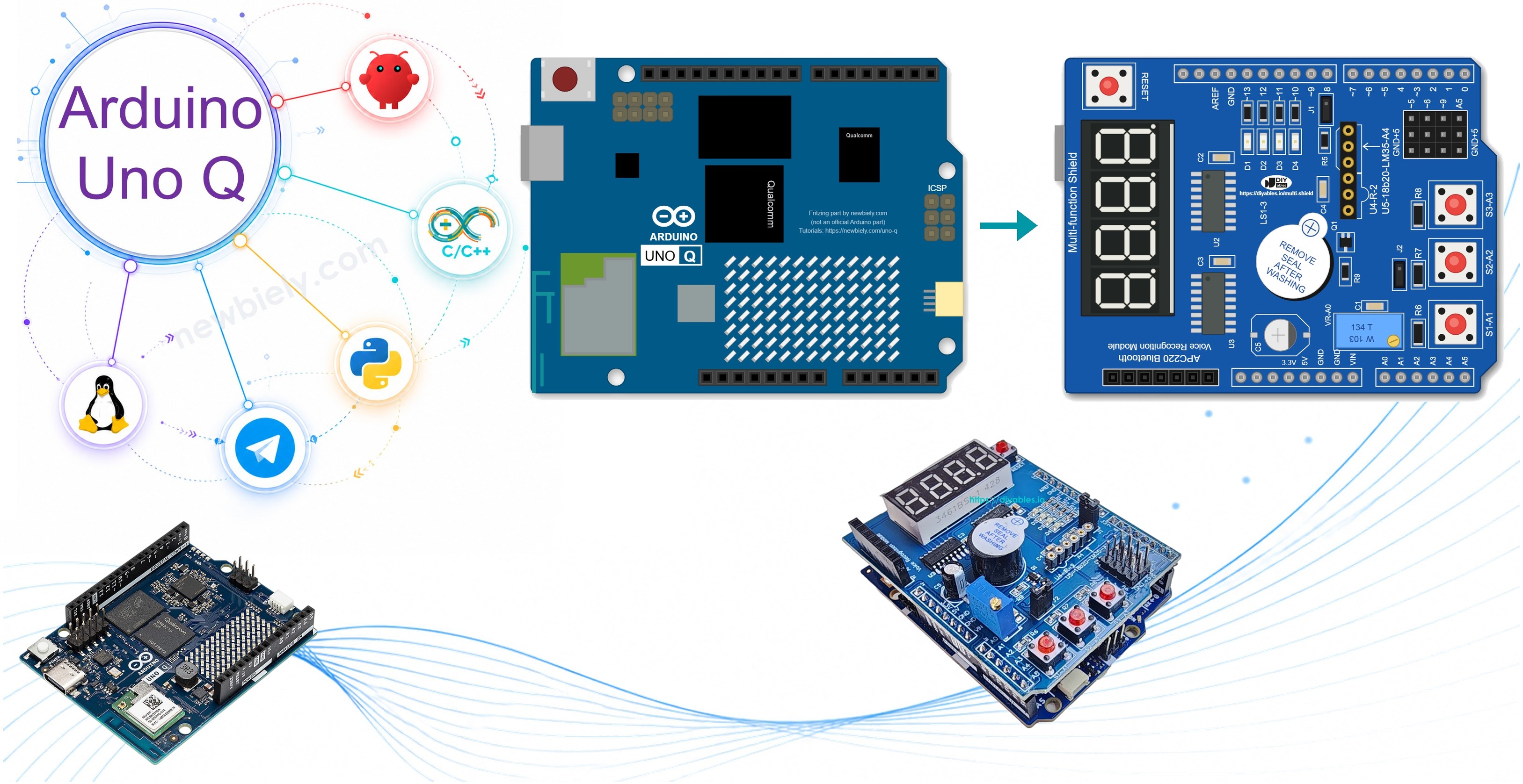
Hardware Preparation
Or you can buy the following kits:
| 1 | × | DIYables Sensor Kit (18 sensors/displays) |
Additionally, some of these links are for products from our own brand, DIYables .
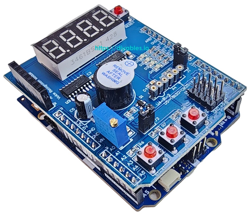
Overview of the Multi-Function Shield
The DIYables Multi-Function Shield packs multiple useful components onto one board that plugs directly into the Arduino UNO Q's MCU headers. No extra wires needed!
What's included on the shield:
- 4-digit 7-segment display — driven via a 74HC595 shift register; shows integers, floats, text, and degree symbols
- Three push buttons (S1, S2, S3) — active LOW with built-in pullup resistors and auto-debounce
- Four LEDs (D1–D4) — active LOW, individually controllable; supports on/off/toggle/blink
- Active buzzer — programmable for short beeps or timed sequences
- Potentiometer on analog pin A0 — returns raw ADC value or percentage
- LM35 temperature sensor on analog pin A4 — remove jumper J1 to enable
Pin mapping (same as Arduino UNO form factor):
| Function | MCU Pin | Function | MCU Pin |
|---|---|---|---|
| LED D1 | D13 | Button S1 | A1 |
| LED D2 | D12 | Button S2 | A2 |
| LED D3 | D11 | Button S3 | A3 |
| LED D4 | D10 | Potentiometer | A0 |
| Buzzer | D3 | LM35 Sensor | A4 |
| Display LATCH | D4 | ||
| Display CLOCK | D7 | ||
| Display DATA | D8 |
Wiring Diagram
No jumper wires or breadboard needed — just align the shield with the Arduino UNO Q's MCU headers and press it into place.
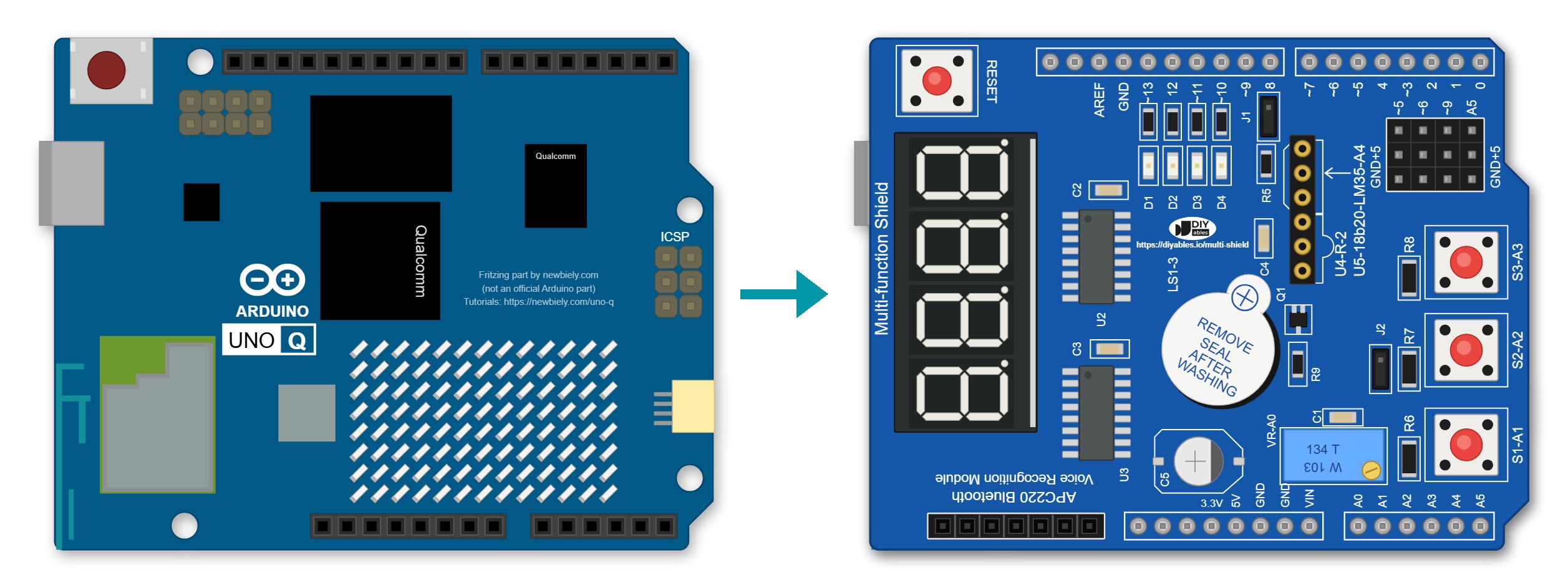
This image is created using Fritzing. Click to enlarge image
Note: To use the LM35 temperature sensor, remove jumper J1 on the shield (A4 is shared with I2C SDA).
WARNING
The MCU pins of the Arduino UNO Q work at 3.3V. Arduino's official pinout says they are 5V tolerant, except A0 and A1. The shield runs on 5V, and it uses exactly these two pins:
- The potentiometer on A0 can give up to 5V. Before you stack the shield, turn its screw about 20 turns counter-clockwise, so it starts at the 0V end. Later, turn it clockwise only until MFS.readPotPercent() reaches 100%. From there on, the voltage goes above 3.3V.
- Button S1 on A1 has a pull-up resistor to 5V (10 kΩ on most versions). Solder an 18 kΩ resistor from A1 to GND on the bottom of the shield. It keeps A1 at about 3.2V when S1 is not pressed.
Arduino UNO Q Code
The Arduino UNO Q has two processors working together:
- The STM32 MCU drives the Multi-Function Shield directly — it controls all components via digital and analog pins
- The Qualcomm MPU runs Debian Linux and handles Wi-Fi, Python, and cloud connectivity
- In this section, only the MCU is programmed — the Linux side stays idle. A later section shows how both processors work together via Bridge.
Important: Always call MFS.loop() inside the Arduino loop() function. It refreshes the display, polls buttons, and manages LED blink timing and buzzer scheduling.
The sketch below cycles through display modes and responds to button presses:
Detailed Instructions
First time with Arduino UNO Q? Follow the Getting Started with Arduino UNO Q tutorial to get your development environment ready before proceeding.
- Connect: First do the two safety steps from the Wiring Diagram section. Then stack the Multi-Function Shield onto the Arduino UNO Q's MCU headers and plug in the USB-C cable.
- Open Arduino App Lab: Launch Arduino App Lab and wait until it detects your Arduino UNO Q — this can take several minutes on first launch.
- Create a new App: Click the Create New App button.
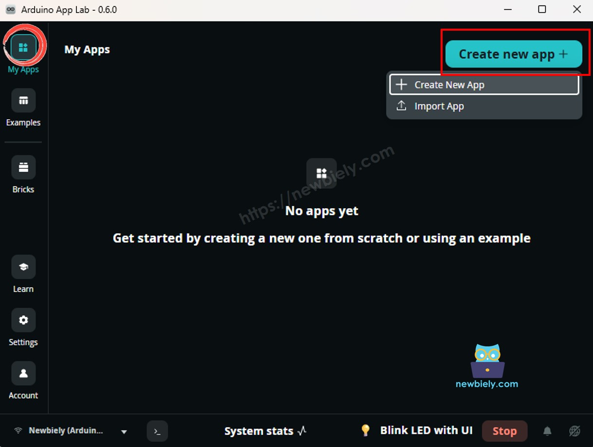
- Give the App a name, for example: DIYables_MultiFuncShield
- Click Create to confirm.
- You will see a set of folders and files generated inside your new App.
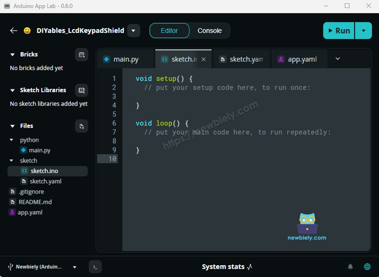
- Find the sketch/sketch.ino file — this is where you will paste the MCU sketch.
- Install the library: Click the Add sketch library button (the open book icon with a + sign) in the left sidebar.
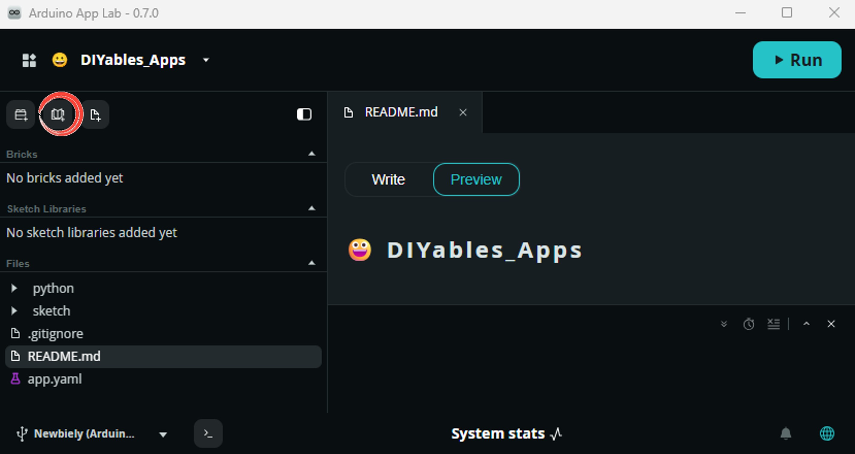
- Search for Arduino_RouterBridge created by Arduino and click the Install button.
- Search for DIYables_MultiFuncShield created by DIYables.io and click the Install button.
- Upload: Click the Run button in Arduino App Lab to compile and upload to the STM32.
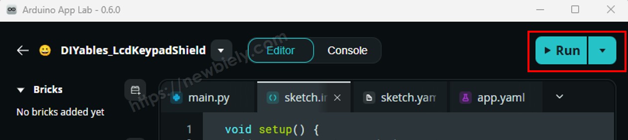
The display cycles through values every 3 seconds, LED D1 blinks, and pressing S1/S2/S3 shows 1111/2222/3333 and beeps!
- Pro Tip: The STM32 MCU on Arduino UNO Q has a 12-bit ADC (values 0–4095). The readPotPercent() function handles scaling automatically.
Bridge: Linux + MCU
This section shows how to program both processors of the Arduino UNO Q so the Linux side can control the Multi-Function Shield remotely:
- The Multi-Function Shield is connected to the MCU (STM32) — the MCU controls all components directly
- The MPU cannot access shield components directly — it must request results from the MCU via Bridge.call()
- The MPU has Wi-Fi — running full Debian Linux, it can connect to the Internet and trigger shield actions remotely
- Arduino_RouterBridge enables RPC communication between the two processors
- ⚠️ /dev/ttyHS1 (Linux) and Serial1 (MCU) are RESERVED by the router — never open them in user code
In short: MCU controls the shield components → MPU sends commands and reads sensor values → MPU can interact with the shield from anywhere over the Internet.
Note: In the Bridge sketch, MFS.loop() is called inside the Arduino loop() to keep the display refreshed and buttons polled — this is required and does not interfere with Bridge communication.
MCU Code (Bridge)
Python Code (Bridge)
Detailed Instructions
- Connect: Stack the Multi-Function Shield onto the Arduino UNO Q and plug in the USB-C cable.
- Open Arduino App Lab: Launch Arduino App Lab and wait for the board to be detected.
- Create a new App: Click Create New App, name it DIYables_MultiFuncShieldBridge, then click Create.
- Paste the MCU sketch: Copy the MCU Bridge code above and paste it into sketch/sketch.ino.
- Paste the Python code: Copy the Python Bridge code above and paste it into the Python file in the App.
- Upload: Click the Run button in Arduino App Lab.
App Lab Console Output
Telegram
Control the Multi-Function Shield from anywhere using Telegram. Show numbers on the display, trigger the buzzer, and read sensor values from your phone.
MCU sketch: Keep the same MCU sketch from the previous Bridge section.
Python Code (Telegram)
Detailed Instructions
- Replace YOUR_TELEGRAM_BOT_TOKEN with your actual bot token from BotFather.
- Replace YOUR_CHAT_ID with your Telegram chat ID.
- Paste this Python code into your App's Python file (keep the same MCU sketch).
- Click the Run button. Open Telegram and send commands to your bot.
App Lab Console Output


ArduinoBot
OpenClaw
You can adapt the OpenClaw to this tutorial by refering the instruction on Arduino Uno Q - OpenClaw Tutorial
Project Ideas
You can build many creative projects using the Multi-Function Shield with Arduino UNO Q:
- Remote Notice Display: Send numbers or codes to the display from Telegram — useful for live score boards, countdown timers, or lab equipment status
- Button-Triggered Alerts: When a button is pressed on the shield, the MCU sends a Telegram notification to your phone via the Bridge
- Remote Potentiometer Reader: Read the knob position remotely via Telegram to monitor physical settings from anywhere
- Smart Environment Monitor: Combine the LM35 sensor with the Bridge to display temperature locally and send alerts via Telegram when thresholds are crossed
- Interactive Quiz Buzzer: Buttons S1/S2/S3 act as quiz answer buzzers — the MCU detects first press and sends the winner's button number via Telegram
Challenge Yourself
Ready to go further with the Multi-Function Shield on Arduino UNO Q? Try these challenges:
- Easy: Modify the MCU sketch to display the potentiometer percentage on the 7-segment display in real time (e.g., "50.0") using MFS.readPotPercent().
- Medium: Add a /led <1-4> <on/off> Telegram command that turns individual LEDs on or off by exposing led1 through led4 control via Bridge functions.
- Advanced: Build a Telegram-driven quiz buzzer system: three people press S1, S2, or S3 — the MCU detects the first press, buzzes, shows the winner's number on the display, and sends a Telegram alert with the result.
How to Connect Other Components
The Multi-Function Shield covers all the pins of the Arduino UNO Q, and it has no female headers on top. So how can you connect other components, such as sensors, relays or motors, to the Arduino UNO Q?
The answer is simple: put a Proto Screw Terminal Block Shield or a Screw Shield V2 between the Arduino UNO Q and the Multi-Function Shield.
- Step 1: Stack the Proto Screw Terminal Block Shield or the Screw Shield V2 on the Arduino UNO Q.
- Step 2: Stack the Multi-Function Shield on the screw shield.
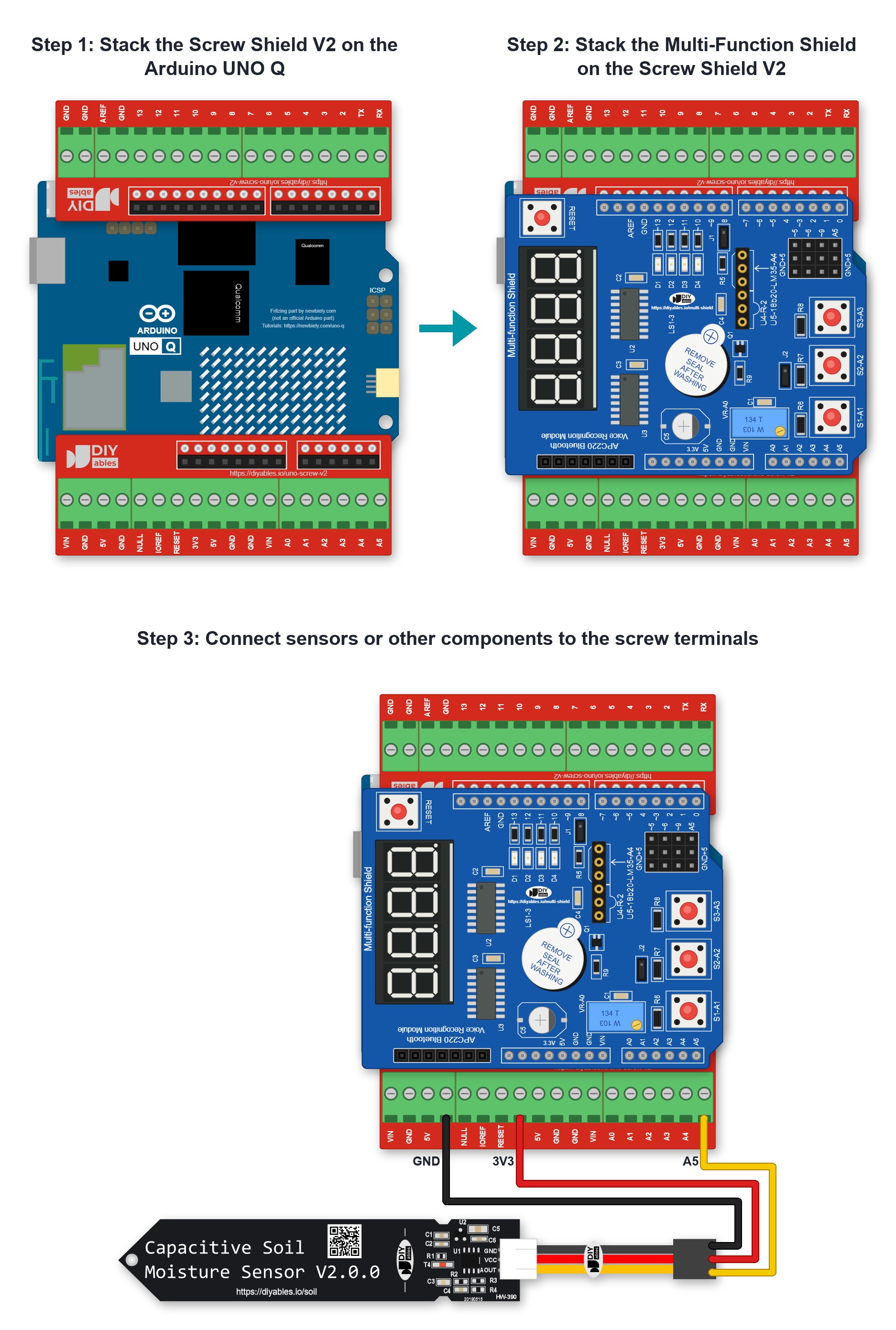
The screw shield has a screw terminal for each pin. It lets you connect the Arduino UNO Q to other components. Do not use the pins that the Multi-Function Shield already uses: D3, D4, D7, D8, D10 to D13 and A0 to A3, and also A4 when you use the LM35 sensor. The free pins are D2, D5, D6, D9 and A5. D2 is free when the U4 socket (for an IR receiver) is empty. The MCU pins of the Arduino UNO Q work at 3.3V, so Step 3 powers the sensor from the 3V3 terminal.