
Raspberry Pi - Slide Switch
A Raspberry Pi often works with no screen and no keyboard. It sits in a box and runs one Python script. But sometimes you still want to give it a simple order by hand: take photos or record video, do the real job or only a dry run, log data or stay idle. A small slide switch is a good tool for this. You set the handle once, and it keeps that setting until you change it. This tutorial instructs you how to use Raspberry Pi to read the position of the DIYables Mini Slide Switch SS12D10 from a Python script that runs over SSH. In detail, we will learn:
- How the SS12D10 is built inside, and how to find its COM leg
- How to wire the switch to GPIO17 (pin 11), 3.3V and ground on the 40-pin header, with no resistor
- How to log every move of the handle with a time stamp, using the RPi.GPIO library and a 50 ms re-check that hides contact bounce
- How to drop the 3.3V wire and switch on the Pi's own pull-up resistor (GPIO.PUD_UP) instead
https://newbiely.com/images/cover/raspberry-pi-slide-switch.jpg
We suggest:
- Utilizing an ON/OFF switch if the switch must sit in the wall or the lid of a case, where a finger can reach it easily.
- Utilizing a DIP switch if one setting is not enough and you need several ON/OFF options in one part. If the input should spring back after each press, see the button module tutorial.
Hardware Preparation
| 1 | × | Raspberry Pi 5 | |
| 1 | × | Mini Slide Switch SS12D10 | |
| 1 | × | Jumper Wires | |
| 1 | × | Recommended: Screw Terminal Block Shield for Raspberry Pi | |
| 1 | × | Recommended: Raspberry Pi Prototyping Base Plate & Breadboard Kit |
Or you can buy the following kits:
| 1 | × | DIYables Sensor Kit (18 sensors/displays) |
Additionally, some of these links are for products from our own brand, DIYables .
Overview of Slide Switch
The SS12D10 from DIYables is a two-position switch, barely bigger than a fingernail. On top, there is a short plastic handle that you move with a fingertip. Under the body, three metal legs stand in one row. The switch is latching: the handle stays at the end where you leave it, even while the Raspberry Pi is turned off. A push button is the opposite. It goes back to its rest position as soon as you let go. In electronics words, the SS12D10 is an SPDT switch (single pole, double throw), also sold as 1P2T.
What happens inside? A small metal bridge slides together with the handle. It always rests on the middle leg, called COM. At the same time, it rests on only one outer leg: the leg on the side where the handle is.
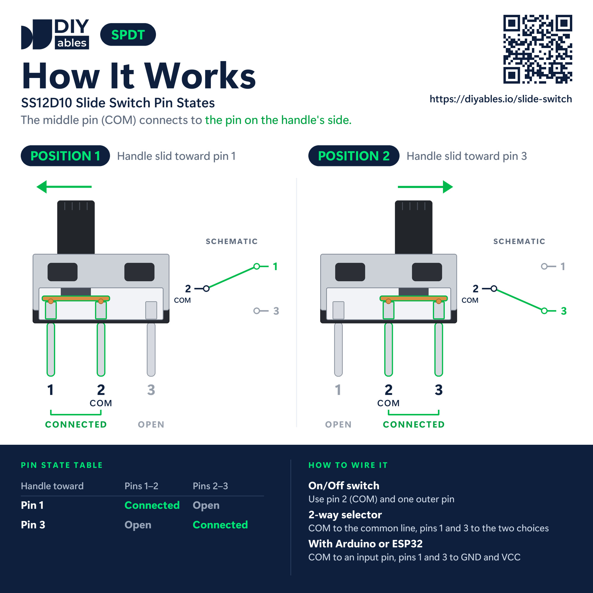
The switch carries no markings, so this tutorial counts the legs along the row:
- Pin 1 (outer leg): This pin must be connected to ground (0V) of the Raspberry Pi
- Pin 2, COM (middle leg): This pin must be connected to a GPIO pin of the Raspberry Pi. It passes on whatever voltage sits on the outer leg that the handle has selected
- Pin 3 (outer leg): This pin must be connected to the 3.3V supply of the Raspberry Pi. In the 2-wire version later on this page, it stays free
The two handle positions in the picture:
- Position 1: slide the handle to the pin 1 end. The bridge now connects pin 1 with COM, and pin 3 is not connected to anything.
- Position 2: slide the handle to the pin 3 end. The bridge now connects COM with pin 3, and pin 1 is not connected to anything.
With the 3-wire wiring of this tutorial, the Python script sees this on GPIO17:
| Handle position | Voltage on COM | GPIO.input(17) returns | The script prints |
|---|---|---|---|
| Pin 1 end | 0V (ground) | 0 (LOW) | OFF |
| Pin 3 end | 3.3V | 1 (HIGH) | ON |
The main data of the switch, from the DIYables product page:
| DIYables Mini Slide Switch SS12D10 | |
|---|---|
| Positions | 2, latching |
| Contact type | SPDT, also called 1P2T |
| Contacts | silver-plated brass, rated AC 125V 2A |
| Number of legs | 3, vertical through-hole |
| Distance between legs | 4.7 mm |
| Leg length | 6.9 mm |
| Body size | roughly 12.8 x 6.7 x 18.2 mm |
| Handle | 5 mm |
| Lifetime | more than 100,000 switching cycles |
| Works from | -25°C to 80°C |
Do not worry about the AC 125V 2A rating. That number is only the upper limit of the contacts. Here, the switch only feeds a very small logic current to GPIO17.
One more thing to know: when the handle moves, the metal bridge bounces for a few milliseconds. A fast Python loop can read 0, 1, 0, 1 before the level settles. Both scripts below check every change a second time after 50 milliseconds, so one move gives one line.
※ NOTE THAT:
Do not look for labels on the SS12D10, because there are none. What counts is the place in the row: the leg in the middle is COM. The two outer legs work the same way. If you mix them up, nothing breaks. The script simply prints ON for the side that used to be OFF.
Wiring Diagram
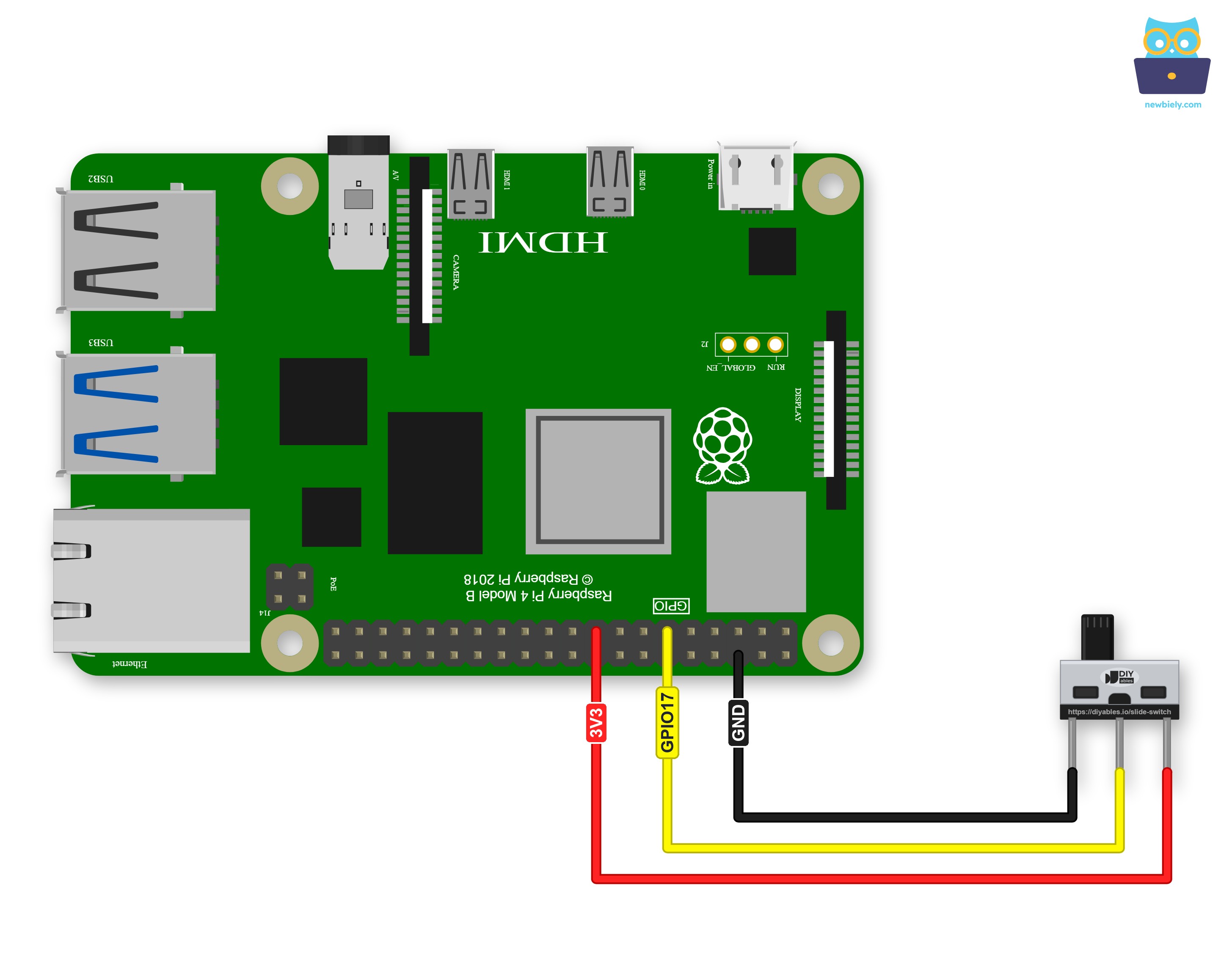
This image is created using Fritzing. Click to enlarge image
| Slide Switch Pin | Raspberry Pi Pin |
|---|---|
| Pin 1 | GND |
| Pin 2 (COM) | GPIO17 |
| Pin 3 | 3.3V |
Where each wire goes on the 40-pin header:
- Slide switch pin 1 to Raspberry Pi GND (pin 6, or any other GND pin). This is the black wire in the diagram.
- Slide switch pin 2 (COM) to Raspberry Pi GPIO17 (pin 11). This is the yellow wire.
- Slide switch pin 3 to Raspberry Pi 3.3V (pin 17, or pin 1). This is the red wire.
In both handle positions, GPIO17 is joined either to 3.3V or to ground. The pin never floats, so you need no resistor at all, and the script turns off the internal pull resistors of the Pi.
Watch out for one trap: the number 17 shows up twice here. GPIO17 is on physical pin 11, while physical pin 17 is a 3.3V pin. The scripts use BCM numbering (GPIO.setmode(GPIO.BCM)), so the code says 17 and means GPIO17 on pin 11.
The legs of the switch are long enough for the end of a female jumper wire to slip on, so you do not need a breadboard. For a project that must last for years, solder the wires to the legs.
※ NOTE THAT:
- Pin 3 of the switch must go to 3.3V (pin 17 or pin 1). NEVER connect it to a 5V pin (pin 2 or pin 4). In the pin 3 position, the switch connects GPIO17 directly to whatever voltage is on pin 3. Raspberry Pi GPIO pins are made for 3.3V only. They are not 5V tolerant, and 5V on GPIO17 can kill that pin or even the whole board.
- GPIO17 must stay an input. Do not use GPIO.OUT on it in any other script while the switch is connected. The switch holds the pin at 3.3V or at ground all the time. If the Pi drove the pin to the opposite level, current would flow straight through the switch: a short circuit.
How To Program for Raspberry Pi to Read the Slide Switch Position
No extra library is needed. RPi.GPIO and the built-in time module do all the work. The most important line sets GPIO17 as an input:
GPIO.PUD_OFF turns off the pull-up and pull-down resistors inside the Pi. The switch itself already drives the pin to 3.3V or to ground, so the Pi does not need to help.
The script reads the handle once at start and reports its position. From then on, the terminal shows nothing until the handle reaches the other end. Each report starts with the time from the Raspberry Pi clock, so you can see when the setting was changed.
Detailed Instructions
- Make sure you have Raspbian or any other Raspberry Pi compatible operating system installed on your Pi.
- Make sure your Raspberry Pi is connected to the same local network as your PC.
- Make sure your Raspberry Pi is connected to the internet if you need to install some libraries.
- If this is the first time you use Raspberry Pi, See how to set up the Raspberry Pi
- Connect your PC to the Raspberry Pi via SSH using the built-in SSH client on Linux and macOS or PuTTY on Windows. See to how connect your PC to Raspberry Pi via SSH.
- Make sure you have the RPi.GPIO library installed. If not, install it using the following command:
- Wire the slide switch to the Raspberry Pi as shown in the wiring diagram above. Check that the red wire is on pin 17 (3.3V), not on a 5V pin.
- Create a Python script file slide_switch.py and add the following code:
- Save the file and run the Python script by executing the following command in the terminal:
- Before you start the script, set the handle to the pin 3 end. Then move it four times, with a short pause after each move: pin 1 end, pin 3 end, pin 1 end, pin 3 end.
- Check the terminal:
The first line tells you where the handle was when the script started. After that, four moves give exactly four lines, each with its own time. The loop checks the pin about 100 times per second, so even a quick flick of the handle is caught. Press Ctrl + C keys in the terminal to stop the script. It then calls GPIO.cleanup() to free GPIO17.
Nothing changes when you move the handle? Check these points:
- The yellow wire must sit on the middle leg of the switch. On an outer leg, GPIO17 only ever sees one level.
- The GPIO17 wire must be on pin 11. Pin 17 is the 3.3V pin, not GPIO17.
- Lines that show up by themselves, with no hand on the switch, mean a loose wire: GPIO17 is floating.
Code Explanation
Check out the line-by-line explanation contained in the comments of the source code!
How To Program for Raspberry Pi to Read the Slide Switch with GPIO.PUD_UP (2 Wires)
The Broadcom chip of the Raspberry Pi has a pull-up resistor built in for each GPIO pin. GPIO.PUD_UP turns it on, and then it can do the job of the 3.3V wire. This is useful when the 3.3V pins are already busy with other modules, or when you want one wire less in a small case. Only two wires are left: COM to GPIO17 and pin 1 to ground.
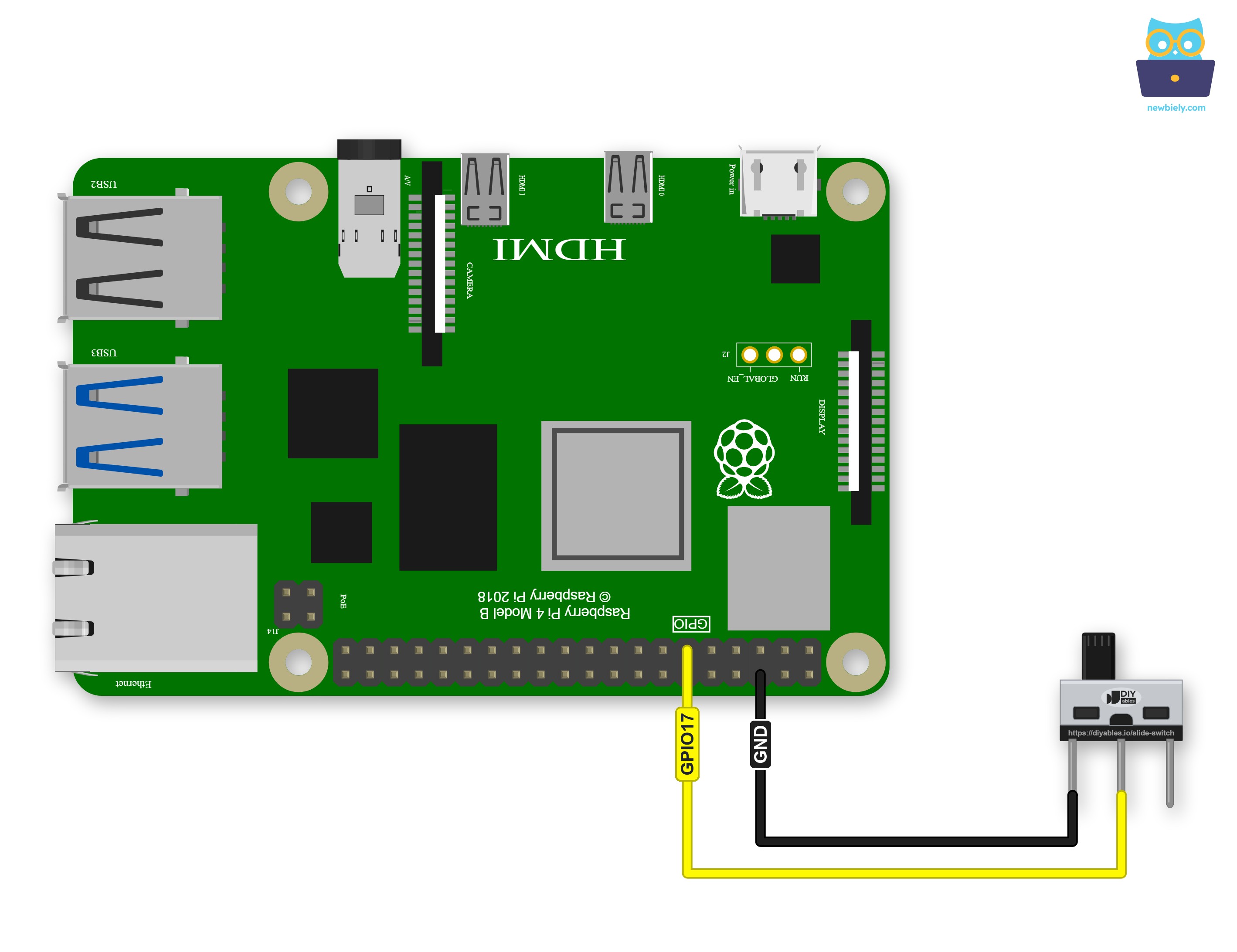
This image is created using Fritzing. Click to enlarge image
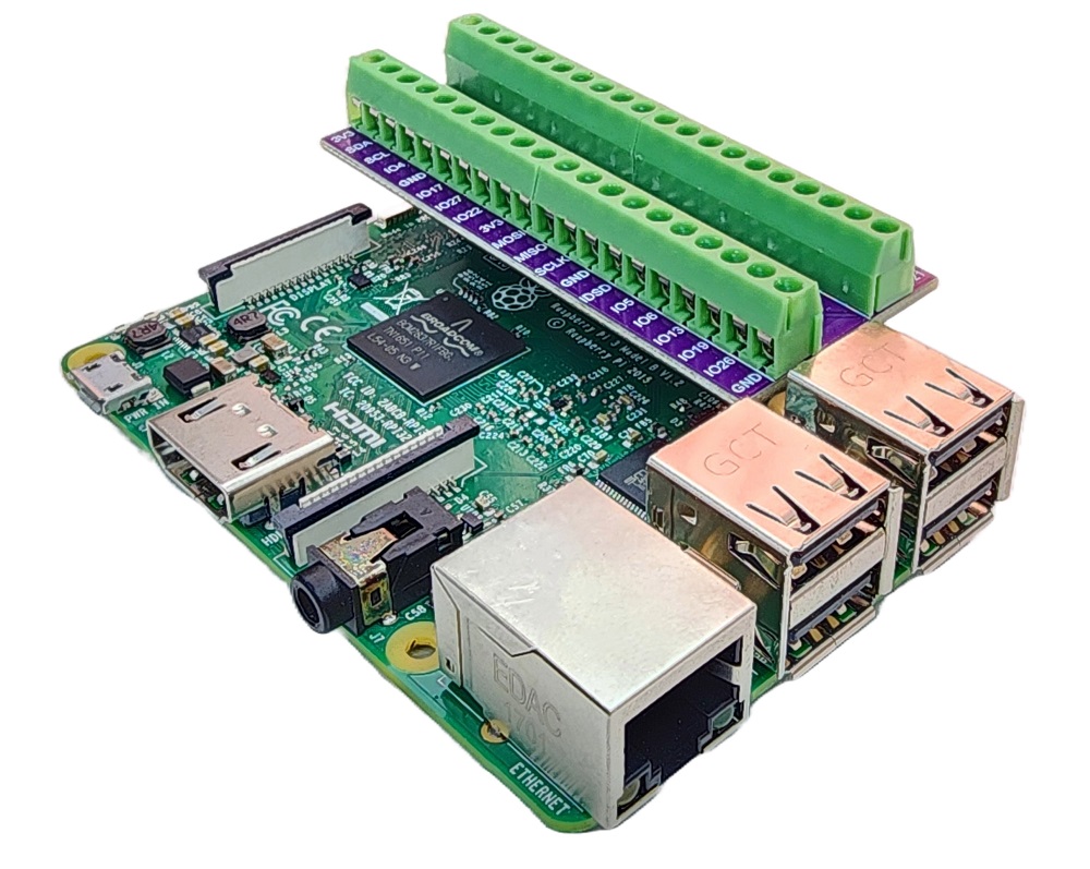
To simplify and organize your wiring setup, we recommend using a Screw Terminal Block Shield for Raspberry Pi. This shield ensures more secure and manageable connections, as shown below:
| Slide Switch Pin | Raspberry Pi Pin |
|---|---|
| Pin 1 | GND |
| Pin 2 (COM) | GPIO17 |
| Pin 3 | not connected |
- Slide switch pin 1 to Raspberry Pi GND (pin 6, or any other GND pin)
- Slide switch pin 2 (COM) to Raspberry Pi GPIO17 (pin 11)
- Slide switch pin 3 stays free
The setup line changes to this:
Be careful, because the meaning of 0 and 1 is now reversed:
- Handle at the pin 1 end: GPIO17 is linked to ground through COM, so GPIO.input(17) gives 0. The script shows ON.
- Handle at the pin 3 end: pin 3 is unwired, so COM leads nowhere. The internal pull-up holds GPIO17 at 3.3V, GPIO.input(17) gives 1, and the script shows OFF.
Detailed Instructions
- If the first script is still running, stop it with Ctrl + C.
- Remove the red wire completely: take it off pin 3 of the switch and off pin 17 of the Raspberry Pi. Then no loose 3.3V wire end hangs near the board. The black wire and the yellow wire stay where they are.
- Create a Python script file slide_switch_input_pullup.py and add the following code:
- Save the file and run it with this command:
- This time, put the handle at the pin 1 end before you start the script. Then move it three times: first to the pin 3 end, then back to pin 1, then to pin 3 again.
- Check the terminal:
Look at the GPIO17 numbers. In the first test, 0 went with OFF. Now 0 goes with ON: with the handle at the pin 1 end, the switch pulls GPIO17 to ground, and the script treats that as ON. Press Ctrl + C keys to stop the script.
Additional Knowledge
3 Wires (PUD_OFF) vs 2 Wires (PUD_UP)
Let's compare the two wirings from this tutorial:
| 3 Wires with GPIO.PUD_OFF | 2 Wires with GPIO.PUD_UP | |
|---|---|---|
| Wires | GND, GPIO17 and 3.3V | GND and GPIO17 |
| Pin 3 of the switch | on 3.3V (pin 17) | not connected |
| What sets the HIGH level | the 3.3V wire through the switch | the pull-up resistor inside the Pi |
| Handle at the pin 3 end | 1 (HIGH), printed as ON | 1 (HIGH), printed as OFF |
| Handle at the pin 1 end | 0 (LOW), printed as OFF | 0 (LOW), printed as ON |
| Risk if wired wrong | 5V on pin 3 can damage GPIO17 | low, no supply wire goes near the switch |
Evidently, three wires give the easy logic, where 1 means ON. Two wires keep the 3.3V pins free and are a little safer, because no supply voltage is routed to the switch at all.
Project Ideas with the Slide Switch
- Boot mode selector: a Python script that starts at boot reads the switch once and picks its job, for example "camera recorder" or "web server".
- Maintenance switch: while the handle is on OFF, a kiosk or display script pauses, so you can log in over SSH and update files in peace.
- Privacy switch: stop the camera or microphone recording as soon as the handle moves to OFF.
- Data logger switch: write sensor values to a CSV file only while the switch is ON.