DIYables Web Apps Web Digital Pins

WebDigitalPins Example - Setup Instructions

Overview

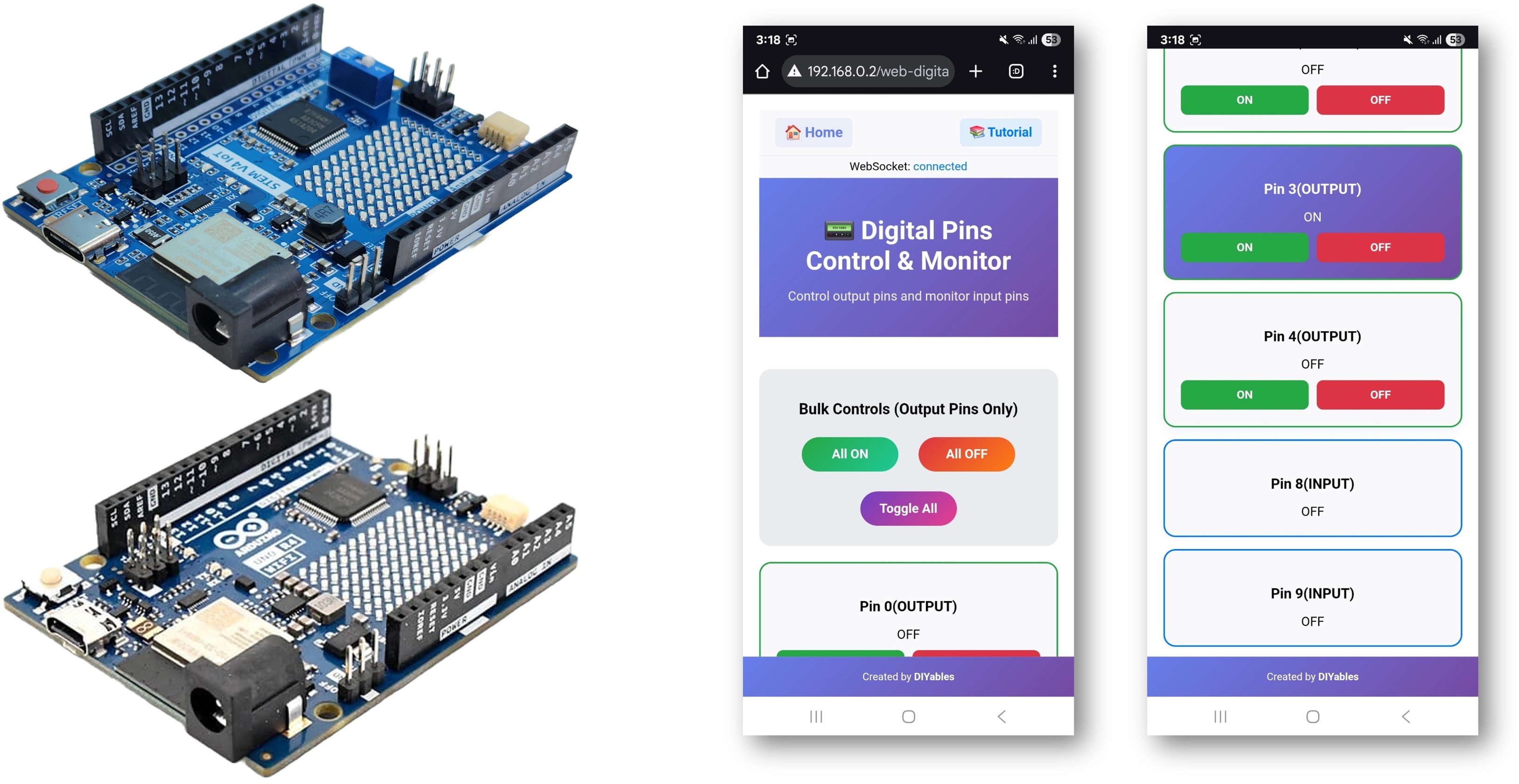
The WebDigitalPins example provides a web-based interface to control and monitor all digital pins on your Arduino. Designed for Arduino Uno R4 WiFi and DIYables STEM V4 IoT educational platform with enhanced GPIO capabilities, extended pin configurations, and built-in educational features for learning digital electronics. You can turn pins on/off, monitor their states in real-time, and perform bulk operations through an intuitive web interface.

Arduino WebDigitalPins Example - Digital Pin Control Interface Tutorial

Features

  • Individual Pin Control: Control each digital pin (0-13) separately
  • Real-time Status: Monitor pin states with visual indicators
  • Bulk Operations: Control all pins at once (All ON, All OFF, Toggle All)
  • Pin Configuration: Set pins as Input or Output via web interface
  • Visual Feedback: Color-coded buttons show pin states (green=ON, red=OFF)
  • Responsive Design: Works on desktop, tablet, and mobile devices
  • WebSocket Communication: Instant updates without page refresh
  • Platform Extensible: Currently implemented for Arduino Uno R4 WiFi, but can be extended for other hardware platforms. See DIYables_WebApps_ESP32

Hardware Preparation

1×Arduino UNO R4 WiFi
1×Alternatively, DIYables STEM V4 IoT
1×USB Cable Type-A to Type-C (for USB-A PC)
1×USB Cable Type-C to Type-C (for USB-C PC)
1×Recommended: Screw Terminal Block Shield for Arduino UNO R4
1×Recommended: Breadboard Shield for Arduino UNO R4
1×Recommended: Enclosure for Arduino UNO R4
1×Recommended: Power Splitter for Arduino UNO R4
1×Recommended: Prototyping Base Plate & Breadboard Kit for Arduino UNO

Or you can buy the following kits:

1×DIYables STEM V4 IoT Starter Kit (Arduino included)
1×DIYables Sensor Kit (30 sensors/displays)
1×DIYables Sensor Kit (18 sensors/displays)
Disclosure: Some of the links provided in this section are Amazon affiliate links. We may receive a commission for any purchases made through these links at no additional cost to you.
Additionally, some of these links are for products from our own brand, DIYables .

Setup Instructions

Detailed Instructions

Follow these instructions step by step:

  • If this is your first time using the Arduino Uno R4 WiFi/DIYables STEM V4 IoT, refer to the tutorial on setting up the environment for Arduino Uno R4 WiFi/DIYables STEM V4 IoT in the Arduino IDE.
  • Connect the Arduino Uno R4/DIYables STEM V4 IoT board to your computer using a USB cable.
  • Launch the Arduino IDE on your computer.
  • Select the appropriate Arduino Uno R4 board (e.g., Arduino Uno R4 WiFi) and COM port.
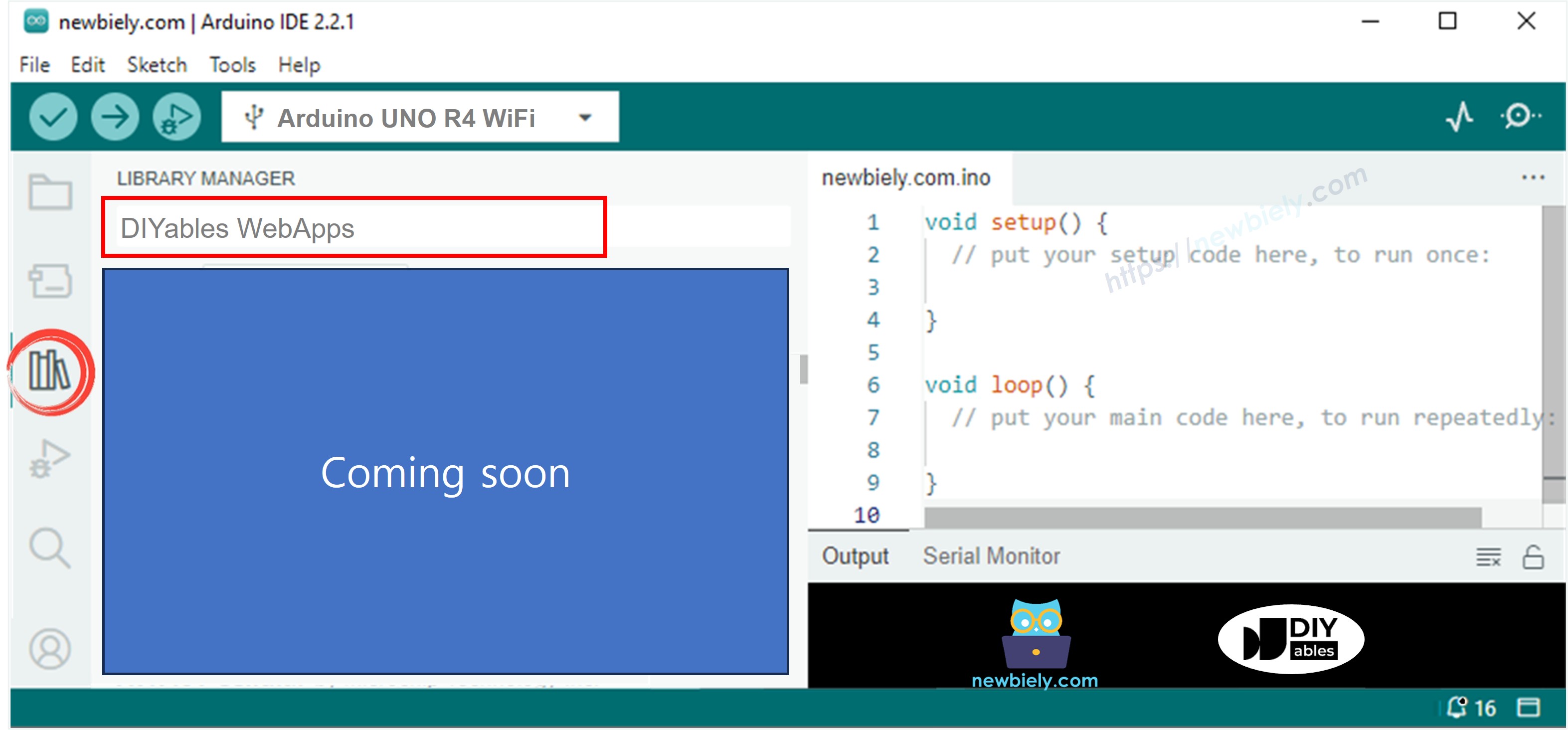
  • Navigate to the Libraries icon on the left bar of the Arduino IDE.
  • Search "DIYables WebApps", then find the DIYables WebApps library by DIYables
  • Click Install button to install the library.
Arduino UNO R4 DIYables WebApps library
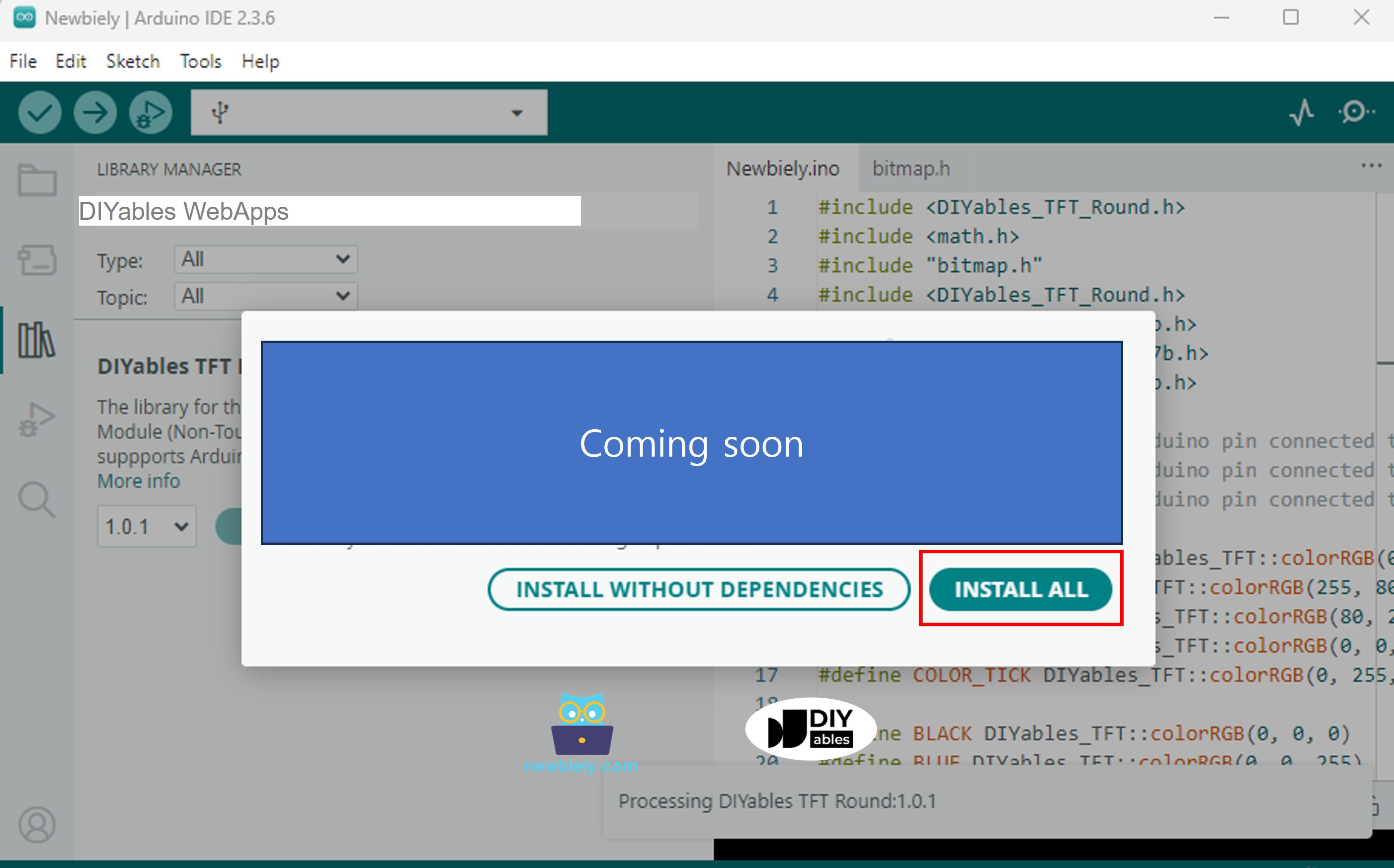
  • You will be asked for installing some other library dependencies
  • Click Install All button to install all library dependencies.
Arduino UNO R4 DIYables WebApps dependency
  • On Arduino IDE, Go to File Examples DIYables WebApps WebDigitalPins example, or copy the above code and paste it to the editor of Arduino IDE
/* * DIYables WebApp Library - Web Digital Pins Example * * This example demonstrates the Web Digital Pins feature with automatic command handling: * - Control output pins 0-13 via web interface * - Monitor input pins 0-13 in real-time * - Individual pin ON/OFF control for outputs * - Real-time pin status feedback for inputs * - Bulk operations (All ON, All OFF, Toggle All) for outputs * * Hardware: Arduino Uno R4 WiFi or DIYables STEM V4 IoT * * Setup: * 1. Update WiFi credentials below * 2. Upload the sketch to your Arduino * 3. Open Serial Monitor to see the IP address * 4. Navigate to http://[IP_ADDRESS]/webdigitalpins */ #include <DIYablesWebApps.h> // WiFi credentials - UPDATE THESE WITH YOUR NETWORK const char WIFI_SSID[] = "YOUR_WIFI_SSID"; const char WIFI_PASSWORD[] = "YOUR_WIFI_PASSWORD"; // Create WebApp server and page instances using platform abstraction UnoR4ServerFactory serverFactory; DIYablesWebAppServer webAppsServer(serverFactory, 80, 81); DIYablesHomePage homePage; DIYablesWebDigitalPinsPage webDigitalPinsPage; // Array to store the state of each digital pin (0-13). Index corresponds to pin number. int pinStates[16] = { 0 }; // Initialize all states to LOW (0) void setup() { Serial.begin(9600); delay(1000); Serial.println("DIYables WebApp - Web Digital Pins Example"); // Add home and digital pins pages webAppsServer.addApp(&homePage); webAppsServer.addApp(&webDigitalPinsPage); // Optional: Add 404 page for better user experience webAppsServer.setNotFoundPage(DIYablesNotFoundPage()); // Pin Configuration Examples: // Method 1: Enable specific pins individually for output control webDigitalPinsPage.enablePin(0, WEB_PIN_OUTPUT); // Enable pin 0 (TX - use with caution) webDigitalPinsPage.enablePin(1, WEB_PIN_OUTPUT); // Enable pin 1 (RX - use with caution) webDigitalPinsPage.enablePin(2, WEB_PIN_OUTPUT); webDigitalPinsPage.enablePin(3, WEB_PIN_OUTPUT); webDigitalPinsPage.enablePin(4, WEB_PIN_OUTPUT); //webDigitalPinsPage.enablePin(5, WEB_PIN_OUTPUT); // Comment/uncomment to disable/enable //webDigitalPinsPage.enablePin(6, WEB_PIN_OUTPUT); // Comment/uncomment to disable/enable webDigitalPinsPage.enablePin(13, WEB_PIN_OUTPUT); // Enable pin 13 (built-in LED) // Method 2: Enable pins for input monitoring webDigitalPinsPage.enablePin(8, WEB_PIN_INPUT); webDigitalPinsPage.enablePin(9, WEB_PIN_INPUT); //webDigitalPinsPage.enablePin(10, WEB_PIN_INPUT); // Comment/uncomment to disable/enable //webDigitalPinsPage.enablePin(11, WEB_PIN_INPUT); // Comment/uncomment to disable/enable // Method 3: Enable all pins at once (uncomment to use) // for (int pin = 0; pin <= 13; pin++) { // webDigitalPinsPage.enablePin(pin, WEB_PIN_OUTPUT); // or WEB_PIN_INPUT as needed // } // Method 4: Enable pins in a range using for loop (uncomment to use) // for (int pin = 7; pin <= 11; pin++) { // webDigitalPinsPage.enablePin(pin, WEB_PIN_OUTPUT); // or WEB_PIN_INPUT as needed // } // Initialize enabled pins int outputPins[] = { 0, 1, 2, 3, 4, 13 }; // Note: Pins 0,1 are TX/RX - use with caution for (int i = 0; i < 6; i++) { int pin = outputPins[i]; pinMode(pin, OUTPUT); digitalWrite(pin, LOW); pinStates[pin] = LOW; } int inputPins[] = { 8, 9 }; for (int i = 0; i < 2; i++) { int pin = inputPins[i]; pinMode(pin, INPUT); // Use INPUT_PULLUP if needed pinStates[pin] = digitalRead(pin); } // Start the WebApp server if (!webAppsServer.begin(WIFI_SSID, WIFI_PASSWORD)) { while (1) { Serial.println("Failed to start WebApp server!"); delay(1000); } } // Return the current state to display on Web App webDigitalPinsPage.onPinRead([](int pin) { return pinStates[pin]; // Return the current state of the pin // You can implement custom read logic here if needed }); // Handle the control request from Web App (for output pins) webDigitalPinsPage.onPinWrite([](int pin, int state) { digitalWrite(pin, state); pinStates[pin] = state; // You can implement custom control logic here if needed }); // Handle pin mode change requests (optional) webDigitalPinsPage.onPinModeChange([](int pin, int mode) { if (mode == WEB_PIN_OUTPUT) { pinMode(pin, OUTPUT); digitalWrite(pin, LOW); pinStates[pin] = LOW; } else if (mode == WEB_PIN_INPUT) { pinMode(pin, INPUT); // or INPUT_PULLUP as needed pinStates[pin] = digitalRead(pin); } // You can implement custom mode change logic here if needed }); } void loop() { // Handle WebApp server communications webAppsServer.loop(); // Monitor input pins for real-time updates static unsigned long lastInputCheck = 0; if (millis() - lastInputCheck > 100) { // Check every 100ms lastInputCheck = millis(); // Check input pins for changes and send real-time updates int inputPins[] = { 8, 9 }; for (int i = 0; i < 2; i++) { int pin = inputPins[i]; int currentState = digitalRead(pin); if (currentState != pinStates[pin]) { pinStates[pin] = currentState; // Send real-time update to web clients webDigitalPinsPage.updatePinState(pin, currentState); } } } // Add your main application code here delay(10); }
  • Configure WiFi credentials in the code by updating these lines:
const char WIFI_SSID[] = "YOUR_WIFI_NETWORK"; const char WIFI_PASSWORD[] = "YOUR_WIFI_PASSWORD";
  • Click Upload button on Arduino IDE to upload code to Arduino UNO R4/DIYables STEM V4 IoT
  • Open the Serial Monitor
  • Check out the result on Serial Monitor. It looks like the below
COM6
Send
WebSocket client connected from: 192.168.0.5 New WebSocket connection established WebSocket message received: SLIDER:GET_VALUES WebSocket client connected from: 192.168.0.5 New WebSocket connection established WebSocket message received: SLIDER:64,128 DIYables WebApp - Web Digital Pins Example INFO: Added app / INFO: Added app /web-digital-pins DEBUG: Enabling pin 0 with mode OUTPUT DEBUG: Enabling pin 1 with mode OUTPUT DEBUG: Enabling pin 2 with mode OUTPUT DEBUG: Enabling pin 3 with mode OUTPUT DEBUG: Enabling pin 4 with mode OUTPUT DEBUG: Enabling pin 13 with mode OUTPUT DEBUG: Enabling pin 8 with mode INPUT DEBUG: Enabling pin 9 with mode INPUT DIYables WebApp Library Platform: Arduino Uno R4 WiFi Network connected! IP address: 192.168.0.2 HTTP server started on port 80 Configuring WebSocket server callbacks... WebSocket server started on port 81 WebSocket URL: ws://192.168.0.2:81 WebSocket server started on port 81 ========================================== DIYables WebApp Ready! ========================================== 📱 Web Interface: http://192.168.0.2 🔗 WebSocket: ws://192.168.0.2:81 📋 Available Applications: 🏠 Home Page: http://192.168.0.2/ 📟 Digital Pins: http://192.168.0.2/web-digital-pins ==========================================
Autoscroll Show timestamp
Clear output
9600 baud  
Newline  
  • If you do not see anything, reboot Arduino board.
  • Take note of the IP address displayed, and enter this address into the address bar of a web browser on your smartphone or PC.
  • Example: http://192.168.0.2
  • You will see the home page like below image:
Arduino UNO R4 DIYables WebApp Home page with Web Digital Pins app
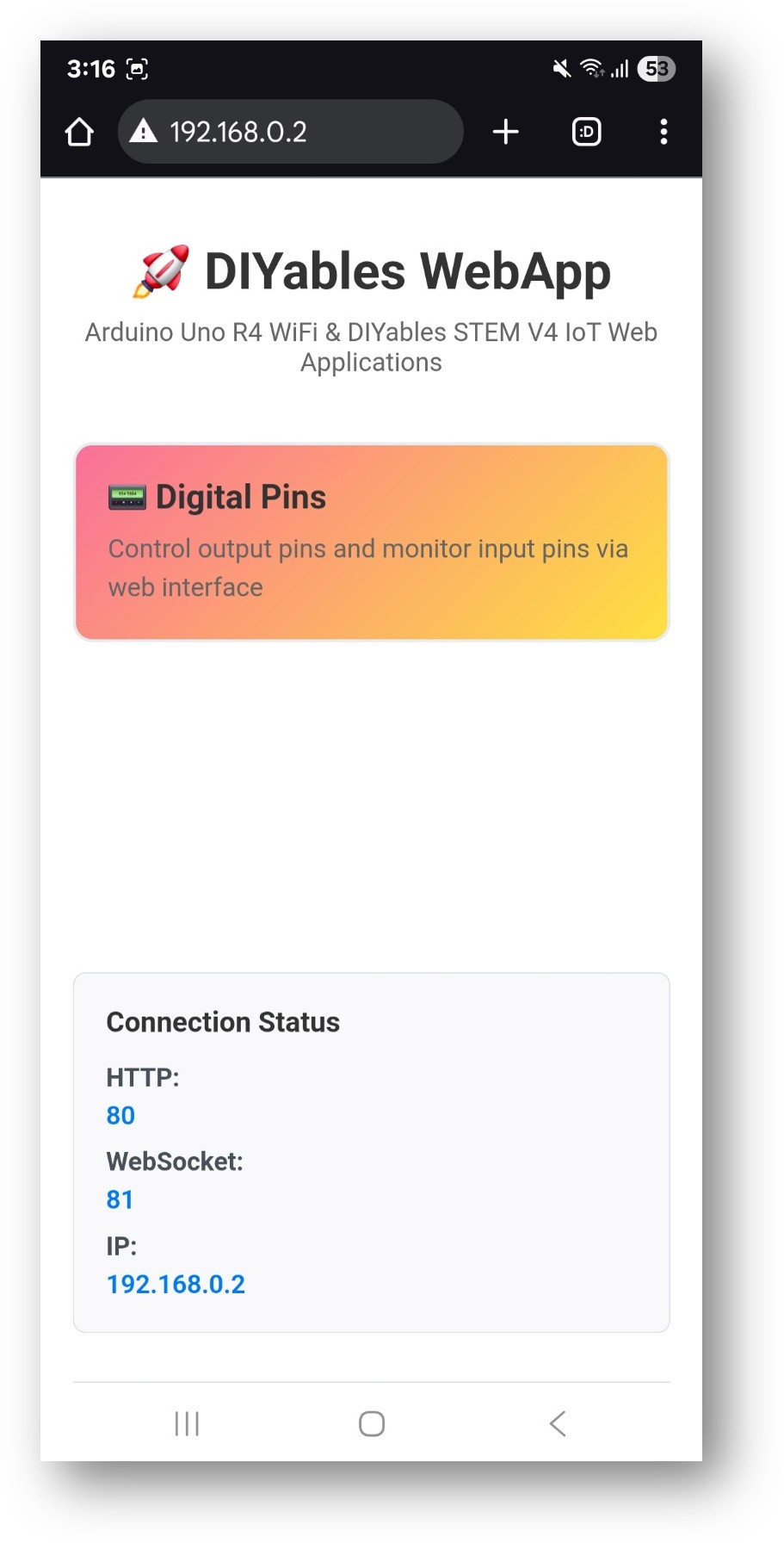
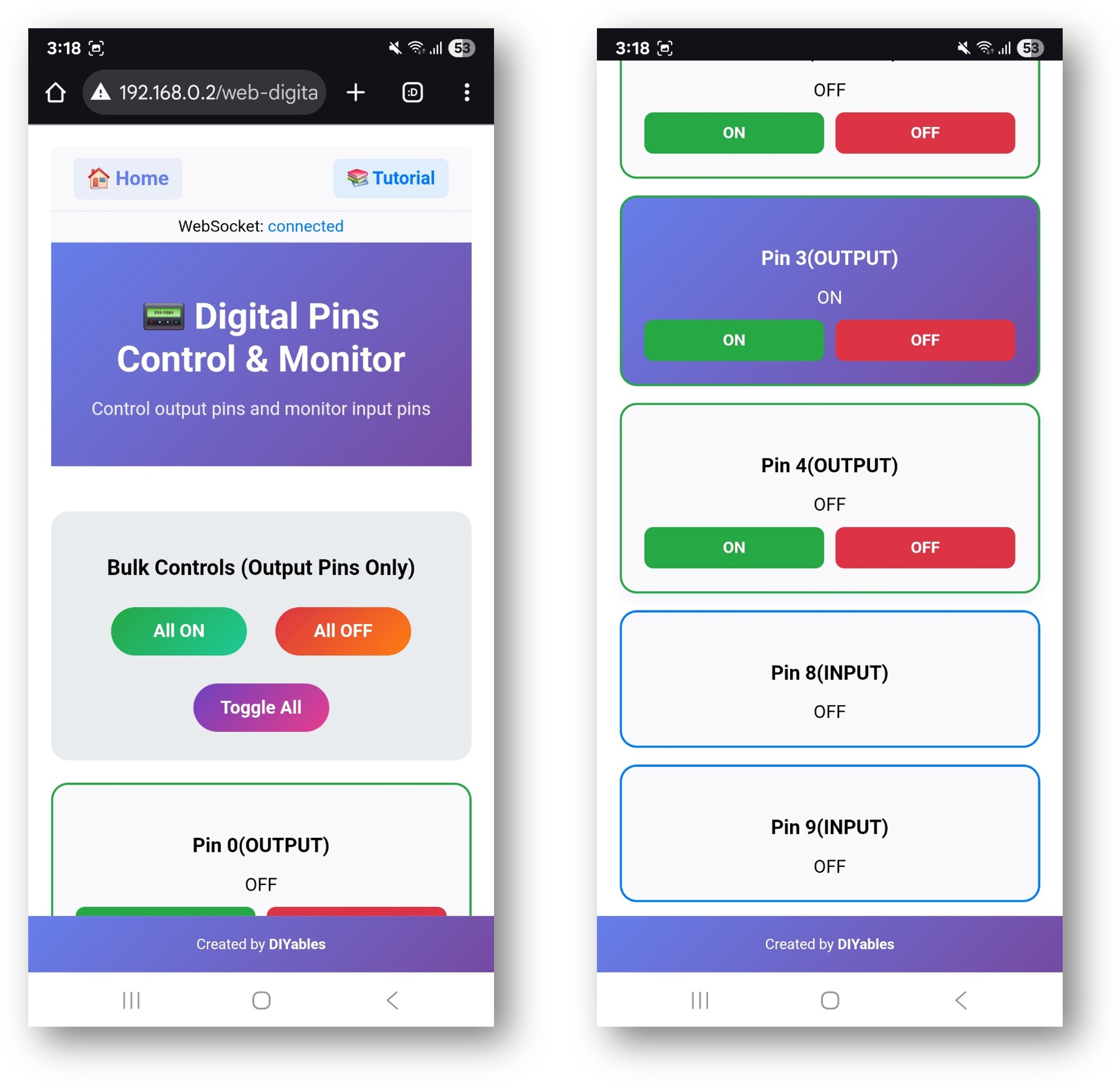
  • Click to the Web Digital Pins link, you will see the Web Digital Pins app's UI like the below:
Arduino UNO R4 DIYables WebApp Web Digital Pins app
  • Or you can also access the page directly by IP address followed by /web-digital-pins. For example: http://192.168.0.2/web-digital-pins
  • Try controlling the digital pins by clicking the pin buttons to turn them ON/OFF and observe the built-in LED (pin 13) responding to your commands.

Creative Customization - Adapt the Code to Your Project

The example shows different ways to configure pins to match your creative project needs:

2. Configure Pin Settings

The example shows different ways to configure pins:

Method 1: Enable Specific Pins
// Enable individual pins for output control webDigitalPinsPage.enablePin(2, WEB_PIN_OUTPUT); // Pin 2 as output webDigitalPinsPage.enablePin(3, WEB_PIN_OUTPUT); // Pin 3 as output webDigitalPinsPage.enablePin(4, WEB_PIN_INPUT); // Pin 4 as input
Method 2: Enable Pin Ranges
// Enable a range of pins for output control webDigitalPinsPage.enableOutputPins(2, 13); // Pins 2-13 as outputs
Method 3: Enable All Pins
// Enable all pins 0-13 for control (use with caution for pins 0,1) webDigitalPinsPage.enableAllPins();

4. Upload the Sketch

  1. Select your Arduino board: Tools → Board → Arduino UNO R4 WiFi
  2. Select the correct port: Tools → Port → [Your Arduino Port]
  3. Click Upload button

5. Get the IP Address

  1. Open Tools → Serial Monitor
  2. Set baud rate to 9600
  3. Wait for Arduino to connect to WiFi
  4. Note the IP address displayed (e.g., 192.168.1.100)

6. Access the Digital Pins Interface

Open your web browser and navigate to:

http://[ARDUINO_IP_ADDRESS]/digital-pins

Example: http://192.168.1.100/digital-pins

How to Use

Pin Control Interface

The web interface displays all configured pins with:

  • Pin Number: Shows which Arduino pin (0-13)
  • Current State: ON (green) or OFF (red) indicator
  • Control Button: Click to toggle pin state
  • Pin Type: Shows if configured as Input or Output

Individual Pin Control

  1. Turn Pin ON: Click the pin button when it shows "OFF"
  2. Turn Pin OFF: Click the pin button when it shows "ON"
  3. Monitor State: Pin buttons update automatically to show current state

Bulk Operations

Use the bulk control buttons to control multiple pins at once:

All ON
  • Turns all configured output pins to HIGH state
  • Input pins are not affected
  • Useful for testing all connected devices
All OFF
  • Turns all configured output pins to LOW state
  • Input pins are not affected
  • Safe way to disable all outputs
Toggle All
  • Inverts the state of all output pins
  • ON pins become OFF, OFF pins become ON
  • Creates interesting lighting effects

Real-time Monitoring

  • Pin states update automatically via WebSocket
  • Changes made in code are reflected in web interface
  • Multiple users can monitor the same Arduino simultaneously

Hardware Connections

Output Pin Examples

LED Control
Arduino Pin → LED (with resistor) → Ground Pin 2 → LED Anode → 220Ω Resistor → Ground Pin 3 → LED Anode → 220Ω Resistor → Ground
Relay Control
Arduino Pin → Relay Input Pin 4 → Relay IN1 Pin 5 → Relay IN2
Motor Control (via Motor Driver)
Arduino Pin → Motor Driver Input Pin 6 → Motor Driver IN1 Pin 7 → Motor Driver IN2 Pin 9 → Motor Driver ENA (PWM)

Input Pin Examples

Switch Input
Switch → Arduino Pin (with pull-up resistor) Switch → Pin 8 → 10kΩ resistor → 5V → GND
Sensor Input
Sensor Signal → Arduino Pin PIR Sensor → Pin 10 Ultrasonic → Pin 11 (Echo)

Code Customization

Adding Pin Change Callbacks

Monitor when pins change state:

void setup() { // Set callback for pin state changes webDigitalPinsPage.onPinChange([](int pin, bool state) { Serial.print("Pin "); Serial.print(pin); Serial.print(" changed to: "); Serial.println(state ? "HIGH" : "LOW"); // Add your custom logic here if (pin == 13 && state == HIGH) { Serial.println("Built-in LED turned ON!"); } }); }

Custom Pin Initialization

Set specific pins to desired states on startup:

void setup() { // Initialize pins to specific states webDigitalPinsPage.setPinState(2, HIGH); // Turn on pin 2 webDigitalPinsPage.setPinState(3, LOW); // Turn off pin 3 // Configure pin modes pinMode(4, INPUT_PULLUP); // Pin 4 as input with pull-up pinMode(5, OUTPUT); // Pin 5 as output }

Reading Input Pins

Monitor input pins in your main loop:

void loop() { static unsigned long lastRead = 0; if (millis() - lastRead > 1000) { // Read every second // Read input pins and update web interface for (int pin = 0; pin <= 13; pin++) { if (webDigitalPinsPage.isPinEnabled(pin) && webDigitalPinsPage.getPinMode(pin) == WEB_PIN_INPUT) { bool currentState = digitalRead(pin); webDigitalPinsPage.updatePinState(pin, currentState); } } lastRead = millis(); } }

Advanced Features

Pin Groups

Create logical groups of pins for related functions:

// Define pin groups const int LED_PINS[] = {2, 3, 4, 5}; const int RELAY_PINS[] = {6, 7, 8, 9}; void controlLEDGroup(bool state) { for (int pin : LED_PINS) { webDigitalPinsPage.setPinState(pin, state); } } void controlRelayGroup(bool state) { for (int pin : RELAY_PINS) { webDigitalPinsPage.setPinState(pin, state); } }

Pattern Generation

Create lighting patterns or sequences:

void runLightPattern() { static unsigned long lastChange = 0; static int currentPin = 2; if (millis() - lastChange > 500) { // Change every 500ms // Turn off all pins for (int pin = 2; pin <= 13; pin++) { webDigitalPinsPage.setPinState(pin, LOW); } // Turn on current pin webDigitalPinsPage.setPinState(currentPin, HIGH); // Move to next pin currentPin++; if (currentPin > 13) currentPin = 2; lastChange = millis(); } }

PWM Control Integration

Combine with analog control for advanced features:

void setup() { // Enable digital pins for on/off control webDigitalPinsPage.enablePin(9, WEB_PIN_OUTPUT); webDigitalPinsPage.enablePin(10, WEB_PIN_OUTPUT); // Set PWM pins for brightness control analogWrite(9, 128); // 50% brightness analogWrite(10, 255); // 100% brightness }

Safety Considerations

Pin Usage Guidelines

Pins 0 & 1 (TX/RX)

  • Used for Serial communication
  • Avoid using unless absolutely necessary
  • Can interfere with programming and debugging

Pin 13 (Built-in LED)

  • Safe to use for testing
  • Built-in LED provides visual feedback
  • Good for initial testing

Pins 2-12

  • Safe for general digital I/O
  • Recommended for most applications
  • No special considerations

Current Limitations

Maximum Current per Pin: 40mA

  • Use current-limiting resistors with LEDs
  • Use transistors or relays for high-current loads
  • Consider total current consumption

Voltage Levels: 3.3V logic

  • Arduino Uno R4 WiFi uses 3.3V logic
  • Ensure connected devices are compatible
  • Use level shifters for 5V devices if needed

Troubleshooting

Common Issues

1. Pin not responding

  • Check pin is enabled in code
  • Verify hardware connections
  • Check for short circuits
  • Confirm pin mode (INPUT/OUTPUT)

2. Web interface not updating

  • Check WebSocket connection status
  • Refresh browser page
  • Verify network connectivity
  • Check Serial Monitor for errors

3. Bulk operations not working

  • Ensure pins are configured as outputs
  • Check for hardware limitations
  • Verify power supply capacity
  • Monitor for overcurrent conditions

4. Input pins showing wrong states

  • Check for proper pull-up/pull-down resistors
  • Verify input signal levels
  • Check for electromagnetic interference
  • Confirm pin configuration

Debug Tips

Enable debug output:

void debugPinStates() { Serial.println("=== Pin States ==="); for (int pin = 0; pin <= 13; pin++) { if (webDigitalPinsPage.isPinEnabled(pin)) { Serial.print("Pin "); Serial.print(pin); Serial.print(": "); Serial.print(digitalRead(pin) ? "HIGH" : "LOW"); Serial.print(" ("); Serial.print(webDigitalPinsPage.getPinMode(pin) == WEB_PIN_OUTPUT ? "OUTPUT" : "INPUT"); Serial.println(")"); } } Serial.println("=================="); }

Project Ideas

Home Automation

  • Control room lights
  • Operate window blinds
  • Control heating/cooling systems
  • Security system integration

Garden Automation

  • Irrigation system control
  • Grow light management
  • Temperature regulation
  • Humidity control

Workshop Control

  • Tool power control
  • Lighting management
  • Ventilation system
  • Safety interlocks

Educational Projects

  • Logic gate demonstrations
  • Traffic light simulation
  • Alarm system projects
  • Remote control experiments

Integration Examples

Motion-Activated Lighting

void setup() { webDigitalPinsPage.enablePin(2, WEB_PIN_OUTPUT); // LED webDigitalPinsPage.enablePin(3, WEB_PIN_INPUT); // PIR sensor pinMode(3, INPUT); } void loop() { if (digitalRead(3) == HIGH) { // Motion detected webDigitalPinsPage.setPinState(2, HIGH); // Turn on LED delay(5000); // Keep on for 5 seconds webDigitalPinsPage.setPinState(2, LOW); // Turn off LED } }

Temperature-Controlled Fan

void loop() { float temperature = getTemperature(); // Your temperature reading function if (temperature > 25.0) { webDigitalPinsPage.setPinState(4, HIGH); // Turn on fan } else { webDigitalPinsPage.setPinState(4, LOW); // Turn off fan } }

Next Steps

After mastering the WebDigitalPins example, try:

  1. WebSlider - For PWM and analog control
  2. WebJoystick - For directional control
  3. WebMonitor - For debugging and monitoring
  4. MultipleWebApps - Combining all features

Support

For additional help:

  • Check the API Reference documentation
  • Visit DIYables tutorials: https://newbiely.com/tutorials/arduino-uno-r4/arduino-uno-r4-diyables-webapps
  • Arduino community forums

※ OUR MESSAGES

  • As freelancers, We are AVAILABLE for HIRE. See how to outsource your project to us
  • Please feel free to share the link of this tutorial. However, Please do not use our content on any other websites. We invested a lot of effort and time to create the content, please respect our work!