
Raspberry Pi - BTS7960 Motor Driver
Picture a heavy rover platform: a metal frame, big 12V gear motors, and a battery that can deliver many amps. A Linux program on the Raspberry Pi decides when the rover drives, turns or stops. But a GPIO pin only gives a weak 3.3V signal, and a big motor would destroy it in a moment. A strong driver must stand between the Pi and the motor, and the BTS7960 module is made for exactly this job. This tutorial instructs you how to use Raspberry Pi to control a 12V DC motor through the BTS7960 motor driver, with a Python script started over SSH. In detail, we will learn:
- What the two power chips on the BTS7960 module do, and what each control pin means
- Which pin states make the motor go forward, go in reverse, brake hard, or roll freely
- How to connect Raspberry Pi, the BTS7960, a 12V power adapter and a 12V DC motor with one shared ground
- How to run a Python script that ramps the motor speed up and down, brakes, reverses and coasts
We suggest:
- Utilizing the DRV8833 motor driver for small battery motors, for example the two wheels of a light robot car.
- Reading the Raspberry Pi - DC Motor tutorial for the basics of speed and direction with a small 5V motor and the DRV8833.
Hardware Preparation
Or you can buy the following kits:
| 1 | × | DIYables Sensor Kit (18 sensors/displays) |
Additionally, some of these links are for products from our own brand, DIYables .
Overview of BTS7960 Motor Driver
The BTS7960 module is a motor driver for currents that small driver boards cannot handle. Shops also sell the same board under the names "IBT-2" and "HW-039". On top of the board, there are two Infineon BTS7960B chips, cooled by a big heat sink under the board. Every chip is half of the bridge, so the two of them make the complete H-bridge. So one module controls one brushed DC motor. It can turn the motor in both directions, and it can change the speed with PWM. Next to the DRV8833 or the L298N, it is a real heavyweight. People use it for large gear motors, car wiper motors, winches, e-scooters, wheelchair motors and heavy robots.
How does it work? Each BTS7960B chip holds one motor wire and can connect it to B+ or to B- of the motor supply. When one chip connects its wire to B+ and the other chip connects its wire to B-, the current flows through the motor in one direction. When the two chips swap these jobs, the current flows the other way, and the motor turns the other way. A PWM signal switches the chip on and off very fast. A longer ON time in each pulse means a faster motor. The Raspberry Pi never switches the 12V itself. It only sends logic signals, and a 74HC14 buffer chip on the module (the product page calls it the isolation chip) passes them on to the two power chips.
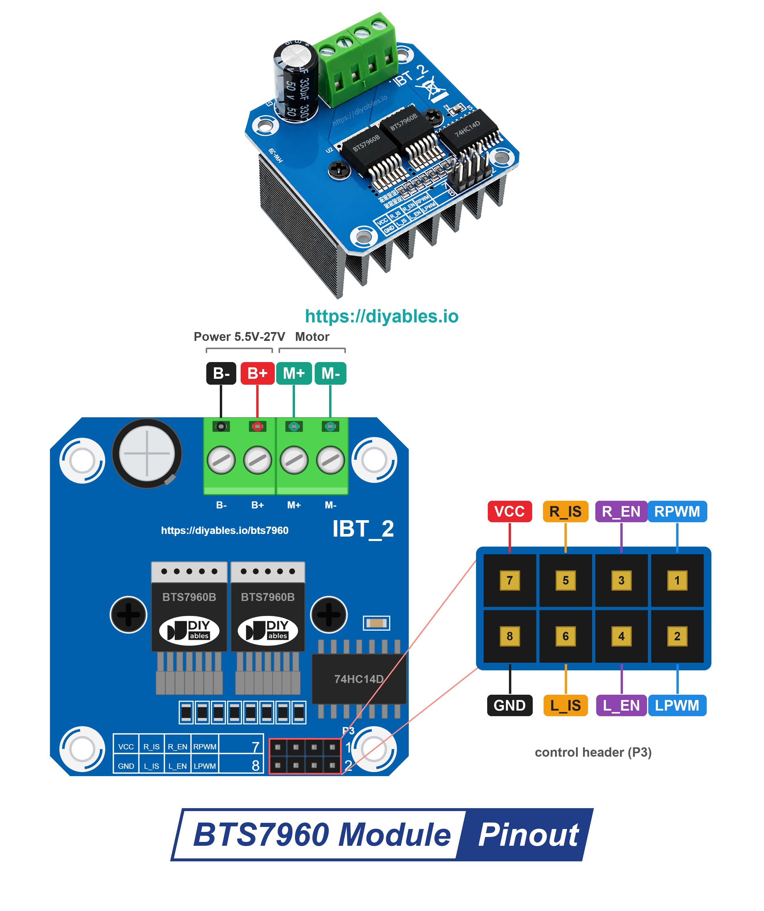
The control side is a header with 8 male pins in two rows of four. The power side is a screw terminal with four positions. Here is the job of each pin:
- RPWM: PWM input of the right half-bridge. A PWM signal on this pin turns the motor forward
- LPWM: PWM input of the left half-bridge. A PWM signal on this pin turns the motor in reverse
- R_EN: enable pin of the right half-bridge. HIGH turns it on, LOW turns it off
- L_EN: enable pin of the left half-bridge. HIGH turns it on, LOW turns it off
- R_IS and L_IS: current-sense and error outputs. This tutorial does not use them, so they must stay unconnected
- VCC: This pin must be connected to a 5V pin of the Raspberry Pi. This pin runs the 74HC14 chip and the power LED, nothing else
- GND: This pin must be connected to ground (0V). On the module, it is already joined to B-
- B+: This terminal must be connected to the positive side of the motor supply (5.5V to 27V DC)
- B-: This terminal must be connected to the negative side of the motor supply
- M+ and M-: the two wires of the DC motor are screwed in here
※ NOTE THAT:
Many factories make this board, and the pin order or the printed names can change between them. For example, many boards print R_IS and L_IS as "R_S" and "L_S". Always follow the labels on your own module, not only the position of the pins in the picture.
The main specs of the module:
| BTS7960 Motor Driver Module | |
|---|---|
| Power chips | 2 x Infineon BTS7960B half-bridge (one full H-bridge) |
| Motors per module | 1 brushed DC motor, both directions |
| Motor supply (B+ and B-) | 5.5V to 27V DC (6V, 12V and 24V systems) |
| Current | up to 43A (the current-limit level of the chip, not a running current) |
| PWM frequency | up to 25 kHz on RPWM and LPWM |
| Logic chip | 74HC14 buffer, powered from the VCC pin |
| Protection | current limiting, over-temperature protection |
How the Four Control Pins Move the Motor
R_EN and L_EN work like a main switch for the two half-bridges. RPWM and LPWM choose the direction and the speed. In Python, the RPi.GPIO library sets a PWM duty cycle from 0 to 100: 0 is the same as LOW, and 100 is the same as HIGH.
| R_EN and L_EN | RPWM | LPWM | What the motor does |
|---|---|---|---|
| HIGH | PWM (duty cycle 0 to 100) | 0 | turns forward, the duty cycle sets the speed |
| HIGH | 0 | PWM (duty cycle 0 to 100) | turns in reverse, the duty cycle sets the speed |
| HIGH | 0 | 0 | brakes, the driver joins the two motor wires, so the motor stops fast |
| LOW | 0 | 0 | coasts, both half-bridges are off, so the motor rolls to a stop by itself |
Keep at least one of RPWM and LPWM at 0 all the time. Never send PWM to both pins at once. The script below has one small function for each row of this table, so it always keeps this rule.
Which stop should a rover use? Brake is the hard stop: the wheels stop almost at once, which helps on a slope or in front of a wall. Coast is the soft stop: the rover rolls on for a short distance and the gears get less shock.
Power and Ground
- The motor gets its power from the 12V power adapter through the DC power jack: the + of the adapter goes to B+, and the - goes to B-. Check that the adapter's current rating is higher than the motor's current.
- Check + and - again before you plug in the adapter. Getting + and - backwards may break the driver board.
- VCC goes to the 5V pin of the Raspberry Pi (pin 4). This pin powers only the buffer chip, and the module maker lists 5V as its supply. The control inputs work with 3.3V signals, so the GPIO pins drive them directly. These inputs have pull-down resistors, and R_IS and L_IS stay unconnected, so nothing comes back from the module and no 5V can reach a GPIO pin.
- GND and B- are joined on the module. One wire from a GND pin of the Pi to the GND pin of the module is enough to give the Pi, the module and the 12V supply the same ground.
- 43A is the current where the chip starts to limit, not a current to run at. For long runs, keep the current far below it. The steady current limit is set by heat: the cooler the heat sink stays, the more the board can carry.
WARNING
B+ carries the full motor voltage (12V here, up to 27V on other systems). Never connect B+, B- or a motor wire to any pin of the Raspberry Pi header. The GPIO pins accept 3.3V only, and 12V will destroy the board.
Wiring Diagram
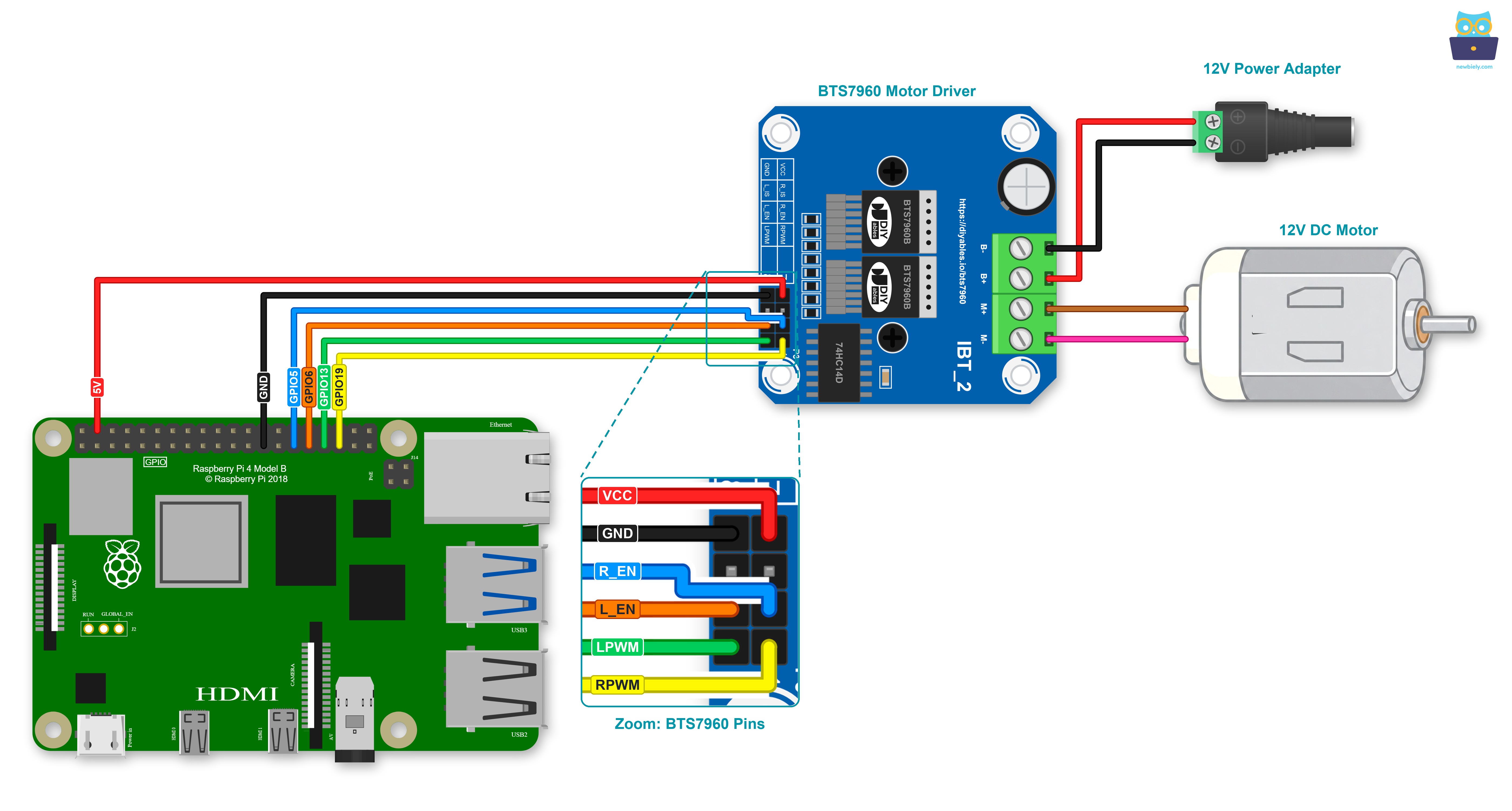
This image is created using Fritzing. Click to enlarge image
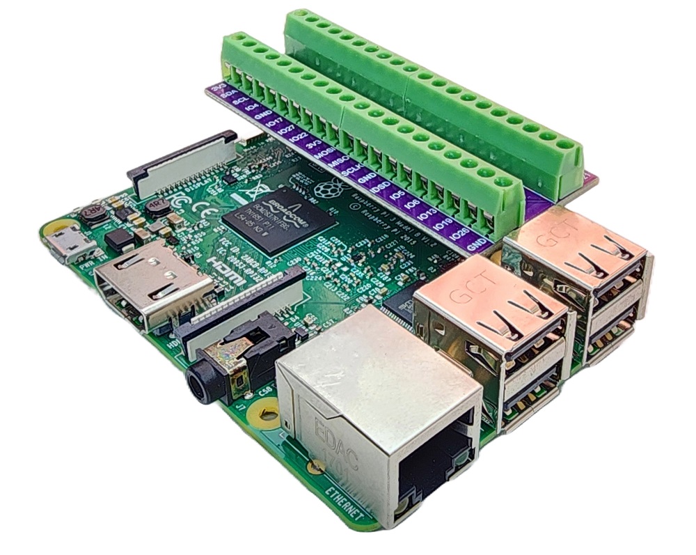
To simplify and organize your wiring setup, we recommend using a Screw Terminal Block Shield for Raspberry Pi. This shield ensures more secure and manageable connections, as shown below:
| BTS7960 Pin | Raspberry Pi Pin | Physical Pin |
|---|---|---|
| RPWM | GPIO19 | pin 35 |
| LPWM | GPIO13 | pin 33 |
| R_EN | GPIO5 | pin 29 |
| L_EN | GPIO6 | pin 31 |
| VCC | 5V | pin 4 |
| GND | GND | pin 25 |
| R_IS and L_IS | not connected | - |
The motor side of the module uses its screw terminal:
- BTS7960 B+ to the + terminal of the DC power jack (12V power adapter)
- BTS7960 B- to the - terminal of the DC power jack
- BTS7960 M+ and M- to the two wires of the 12V DC motor
The GND wire and the four signal wires go to the row of the 40-pin header with the odd pin numbers, so they are easy to count: pins 25, 29, 31, 33 and 35. Only the VCC wire goes to the other row, to pin 4 (5V). Both the Pi header and the module header have male pins, so use female-to-female jumper wires for this part. Keep the 12V adapter unplugged until the wiring is finished.
How To Program for Raspberry Pi to Control a 12V DC Motor with BTS7960
No extra Python package is needed besides RPi.GPIO. The script makes a software PWM signal of 1000 Hz on GPIO19 (RPWM) and GPIO13 (LPWM), which is far below the 25 kHz limit of the BTS7960. Then it runs the motor through this cycle, again and again:
- Forward: the duty cycle on RPWM climbs from 0 to 100% in about 2 seconds
- Forward at 100% for 2 seconds
- Forward: the duty cycle drops back to 0% in about 2 seconds
- Brake for 1 second: RPWM and LPWM are both 0, while R_EN and L_EN stay HIGH
- Reverse at 50% for 2 seconds: the PWM signal moves to LPWM
- Coast for 2 seconds: R_EN and L_EN go LOW, then they go HIGH again before the next forward run
Five short functions keep the main loop easy to read. forward(duty) and reverse(duty) take a duty cycle from 0 to 100. brake() and coast() are the two kinds of stop. enable_driver(on) sets R_EN and L_EN together.
Detailed Instructions
- Check that your Raspberry Pi runs Raspberry Pi OS (Raspbian) or another compatible operating system.
- Your Raspberry Pi and your PC must be on the same local network. The Pi also needs internet access if you have to install a package.
- Is this your first project with a Raspberry Pi? Then see how to set up the Raspberry Pi first.
- Open an SSH connection from your PC to the Raspberry Pi: use the built-in SSH client on Linux and macOS, or PuTTY on Windows. See how connect your PC to Raspberry Pi via SSH.
- The script needs the RPi.GPIO library. It usually comes with Raspberry Pi OS. If it is missing, install it with these commands:
- Wire the Raspberry Pi, the BTS7960 module, the DC power jack and the motor as shown in the wiring diagram above. The 12V adapter should still be unplugged.
- Create a Python script file bts7960_dc_motor.py (for example with nano bts7960_dc_motor.py) and add the following code:
- Save the file (in nano: Ctrl + O, Enter, then Ctrl + X).
- Next, the 12V adapter goes into the DC power jack.
- Start the script with this command:
- Watch the motor and the text in the terminal:
One full round takes about 11 seconds. The motor speeds up, runs at full speed, slows down and stops hard. Then it turns the other way at half speed and finally rolls to a stop on its own. The script repeats this round until you press Ctrl + C keys in the terminal. Then the finally block stops both PWM signals, pulls R_EN and L_EN LOW and releases the GPIO pins, so the motor does not keep running. The last line of the output above shows this moment.
If the motor turns the wrong way while the terminal shows "[forward]", unplug the 12V adapter and swap the two motor wires on M+ and M-.
At a low duty cycle, you may hear a soft, high tone from the motor. The 1000 Hz PWM signal makes this sound, and it is normal.
If the motor does not move at all, check that the 12V adapter is plugged in, that the GND wire sits on pin 25, and that R_EN and L_EN are on pins 29 and 31. Without HIGH on both enable pins, the driver stays off.
Additional Knowledge
BTS7960 vs L298N vs DRV8833
The DRV8833 also has its own Raspberry Pi tutorial on this site. Let's compare the BTS7960 with it and with the older L298N:
| BTS7960 | L298N | DRV8833 | |
|---|---|---|---|
| Motors per module | 1 | 2 | 2 |
| Current | up to 43A (limit level, heat decides the long-run current) | about 2A per motor | about 1.5A per motor (2A peak) |
| Voltage lost inside the driver | very little | about 2V | little |
| Good for | big 12V or 24V motors, heavy rovers, winches | motors that need about 2A | small 2.7V to 10.8V battery motors |
Evidently, the BTS7960 is the right choice when the motor is big and pulls a high current, like the drive motor of a heavy rover. For two small wheels on a light robot car, the DRV8833 is smaller and loses less voltage than the L298N.
From One Motor to a Rover
One BTS7960 module drives one motor. A rover with a left and a right drive motor needs two modules:
- Give the second module its own four GPIO pins for RPWM, LPWM, R_EN and L_EN, and its own VCC (5V) and GND wires.
- Feed both modules from one battery or power supply that can give the current of both motors at the same time.
- To turn on the spot, run one motor forward and the other in reverse, the same way the forward() and reverse() functions of this script do it for one motor.