
Arduino UNO Q - BTS7960 Motor Driver
Picture a small conveyor belt on your workbench. It carries parts along, slows down while you load it, and stops when the box at the end is full. A belt like that needs a strong 12V gear motor, and a strong motor needs a driver that can take the current. That is the job of the BTS7960 module. On the Arduino UNO Q, the STM32 MCU tells the driver how fast and which way to turn. The Linux side then becomes the "boss" that starts, stops and slows down the belt.
What this page covers:
- What the BTS7960 (IBT-2) board is, and the job of each pin on its 8-pin header
- How RPWM, LPWM, R_EN and L_EN make the motor go forward, go in reverse, brake or coast
- Why VCC goes to the 5V pin of the Arduino UNO Q while the signals stay at 3.3V, and why the 12V never touches the board
- How to ramp a 12V motor up and down with a sketch on the MCU
- How Python on the Linux side starts, slows and stops the belt through Bridge
- How to run the belt from your phone with Telegram commands
- How to use OpenClaw on Arduino UNO Q with the BTS7960
Hardware Preparation
Or you can buy the following kits:
| 1 | × | DIYables Sensor Kit (18 sensors/displays) |
Additionally, some of these links are for products from our own brand, DIYables .
The 12V adapter feeds the motor only. The Arduino UNO Q still runs from its USB-C cable. Look up how much current your motor draws, and pick an adapter that can give more than that.
Overview of the BTS7960 Motor Driver
The BTS7960 module is a heavy-duty driver for one brushed DC motor. You may also find it sold as IBT-2 or HW-039. Two Infineon BTS7960B chips sit on top of the board, and a big heat sink bolted underneath keeps them cool. Each chip is a half-bridge: it can switch one motor wire to the plus or to the minus of the supply. Two half-bridges together make a full H-bridge, so the motor can turn both ways. The speed comes from PWM: a higher duty cycle gives the motor more power.
Small drivers such as the DRV8833 are made for toy motors. The BTS7960 is made for motors that do real work: conveyor and winch gear motors, wiper motors, scooter motors and heavy robot wheels.
| Feature | BTS7960 Module |
|---|---|
| Motor supply (B+ / B-) | 5.5V to 27V DC (6V, 12V and 24V systems) |
| Motors | 1 brushed DC motor, both directions |
| Current | up to 43A, where the chip's own current limit kicks in |
| PWM frequency | up to 25 kHz on RPWM and LPWM |
| Logic chip | 74HC14 buffer, powered from the VCC pin |
| Protection | current limiting, over-temperature |
| Extra outputs | R_IS / L_IS, current sense and fault signal |
Do not read 43A as a number to run at all day. At that point the chip already holds the current back. For long runs, stay far below it. How long the board can carry a given current depends on how fast its heat sink loses heat.
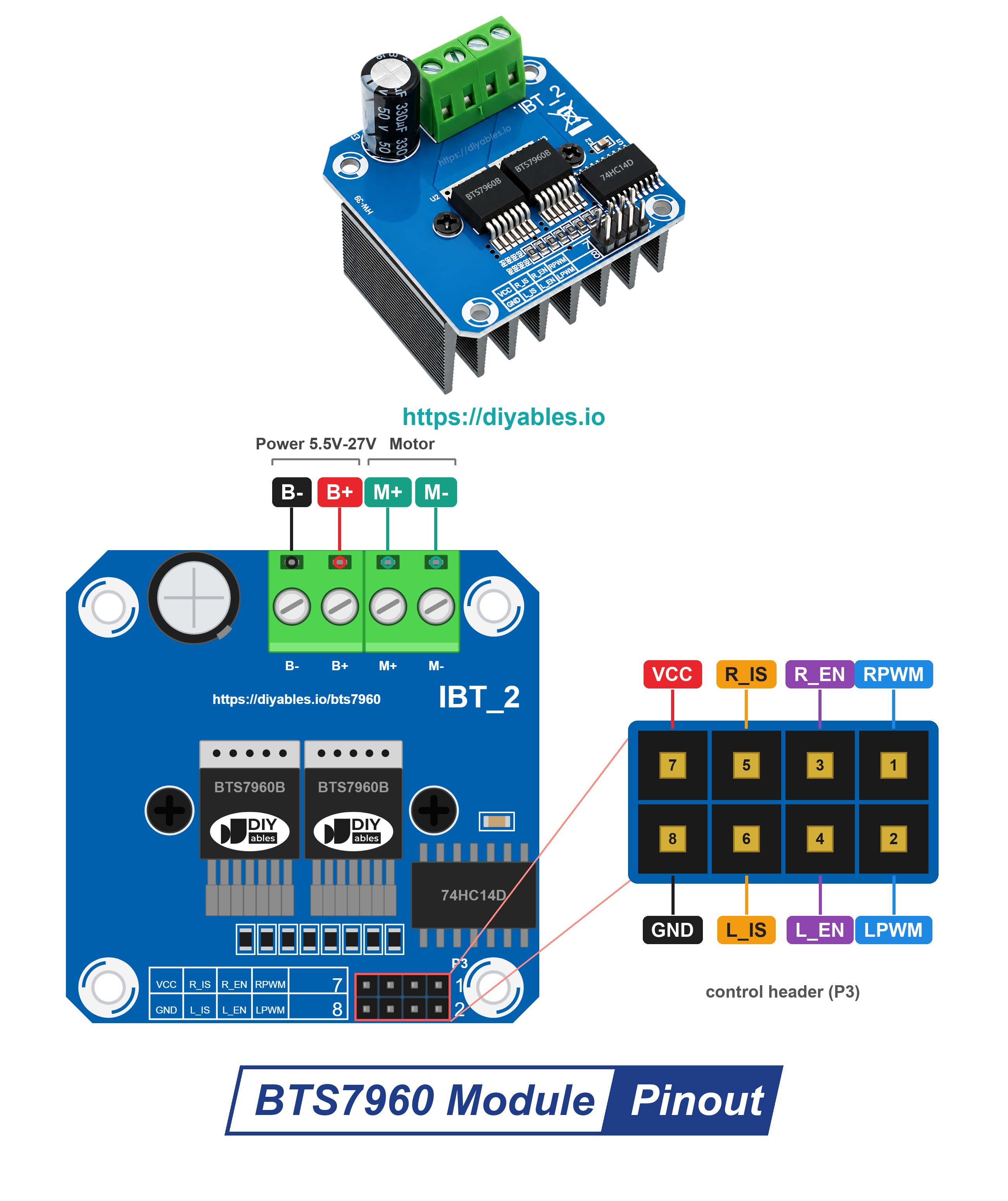
The board has two groups of pins. A 2 x 4 pin header takes the small signals from the Arduino UNO Q. A screw terminal takes the big motor current.
Header pins (to the Arduino UNO Q):
- RPWM (pin 1): PWM input for the forward direction. It runs the right half-bridge.
- LPWM (pin 2): PWM input for the reverse direction. It runs the left half-bridge.
- R_EN (pin 3): Switches the right half-bridge on (HIGH) or off (LOW).
- L_EN (pin 4): Switches the left half-bridge on (HIGH) or off (LOW).
- R_IS / L_IS (pins 5 and 6): Current sense and fault outputs. The board prints them as R_S and L_S. They stay unconnected in this tutorial.
- VCC (pin 7): Powers only the 74HC14 logic chip and the power LED. It does not feed the motor.
- GND (pin 8): Ground. On the module it is joined to B-.
The top row of the header holds VCC, R_IS, R_EN and RPWM. The bottom row holds GND, L_IS, L_EN and LPWM. Always go by the labels printed on your board.
Screw terminal (power side):
- B+ / B-: plus and minus of the motor supply (here, the 12V adapter)
- M+ / M-: the two wires of the DC motor
The 74HC14 chip sits between your board and the power chips. On the product page, this part is called the isolation chip. Your UNO Q pins talk only to this chip, never straight to the BTS7960B chips.
How RPWM, LPWM and the Enable Pins Move the Motor
With R_EN and L_EN both HIGH, the two PWM pins decide what happens:
| RPWM | LPWM | Motor |
|---|---|---|
| PWM (0 to 255) | 0 | Forward, the duty cycle sets the speed |
| 0 | PWM (0 to 255) | Reverse, the duty cycle sets the speed |
| 0 | 0 | Brake, the driver joins the two motor wires and the motor stops fast |
Now pull R_EN and L_EN LOW. Both half-bridges switch off, and nothing holds the motor any more. It coasts and rolls to a stop by itself. On a conveyor, brake is the choice when a part must stop at one exact spot. Coast is fine when the belt only needs to stop at some point.
One rule above all: keep at least one of RPWM and LPWM at 0. Do not drive the two PWM pins together.
※ NOTE THAT:
- VCC goes to the 5V pin of the Arduino UNO Q. VCC feeds only the 74HC14 logic chip, and the module maker specifies 5V for it. The maker lists 3.3V to 5V as the input level, so the 3.3V MCU pins of the UNO Q need no level shifter.
- Nothing comes back to the board. R_IS and L_IS stay free, and the four control inputs have pull-down resistors, so no voltage from the module can reach a UNO Q pin.
- One GND wire gives the common ground. GND and B- are joined on the module, so the GND wire to the UNO Q also ties the board to the minus of the 12V adapter.
- Never connect B+ to the Arduino UNO Q. The 12V belongs on the screw terminal only.
BTS7960 or something smaller? The L298N drives two motors at about 2A each and loses about 2V inside. The BTS7960 drives only one motor, but it takes far more current and loses very little. For small motors, a DRV8833 is enough: see Arduino UNO Q - DRV8833 DC Motor Driver.
Wiring Diagram
The wiring has two sides that never mix. The signal side is six jumper wires from the BTS7960 header to the Arduino UNO Q. The power side is the 12V adapter and the motor, both on the screw terminal.
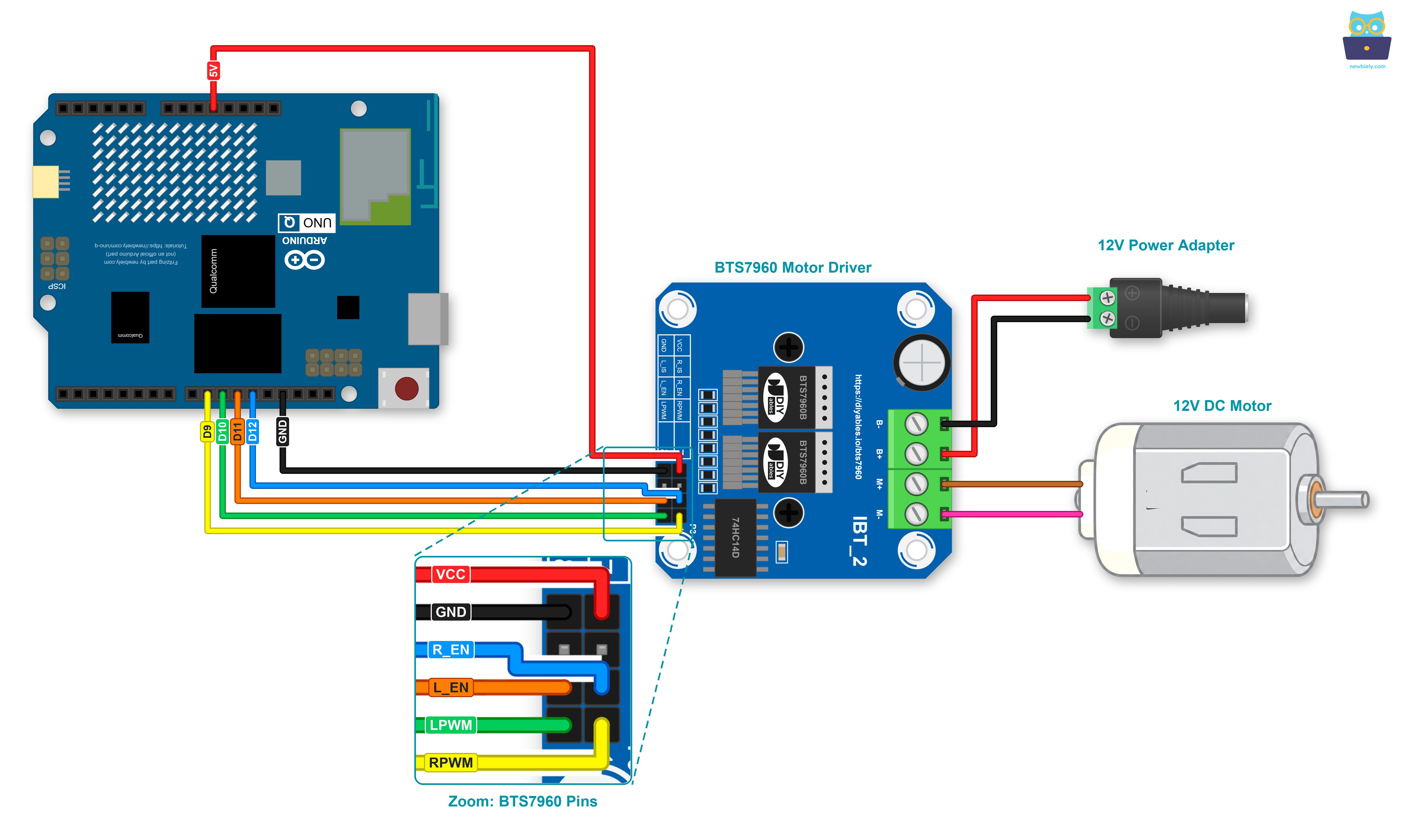
This image is created using Fritzing. Click to enlarge image
| BTS7960 Pin | Goes To |
|---|---|
| RPWM | Arduino UNO Q D9 (PWM) |
| LPWM | Arduino UNO Q D10 (PWM) |
| R_EN | Arduino UNO Q D12 |
| L_EN | Arduino UNO Q D11 |
| VCC | Arduino UNO Q 5V (5V pin) |
| GND | Arduino UNO Q GND |
| R_IS, L_IS | leave free |
| B+ | 12V adapter plus (+), via the DC power jack |
| B- | 12V adapter minus (-), via the DC power jack |
| M+, M- | the two wires of the 12V DC motor |
If the project will run for a long time, or sit inside a box, it is better to fix the wires with screws. Put a Screw Shield V2 or a Proto Screw Terminal Block Shield on top of the Arduino UNO Q, then tighten each wire under a screw. Each wire goes to the screw terminal of the same pin, as in the image below.
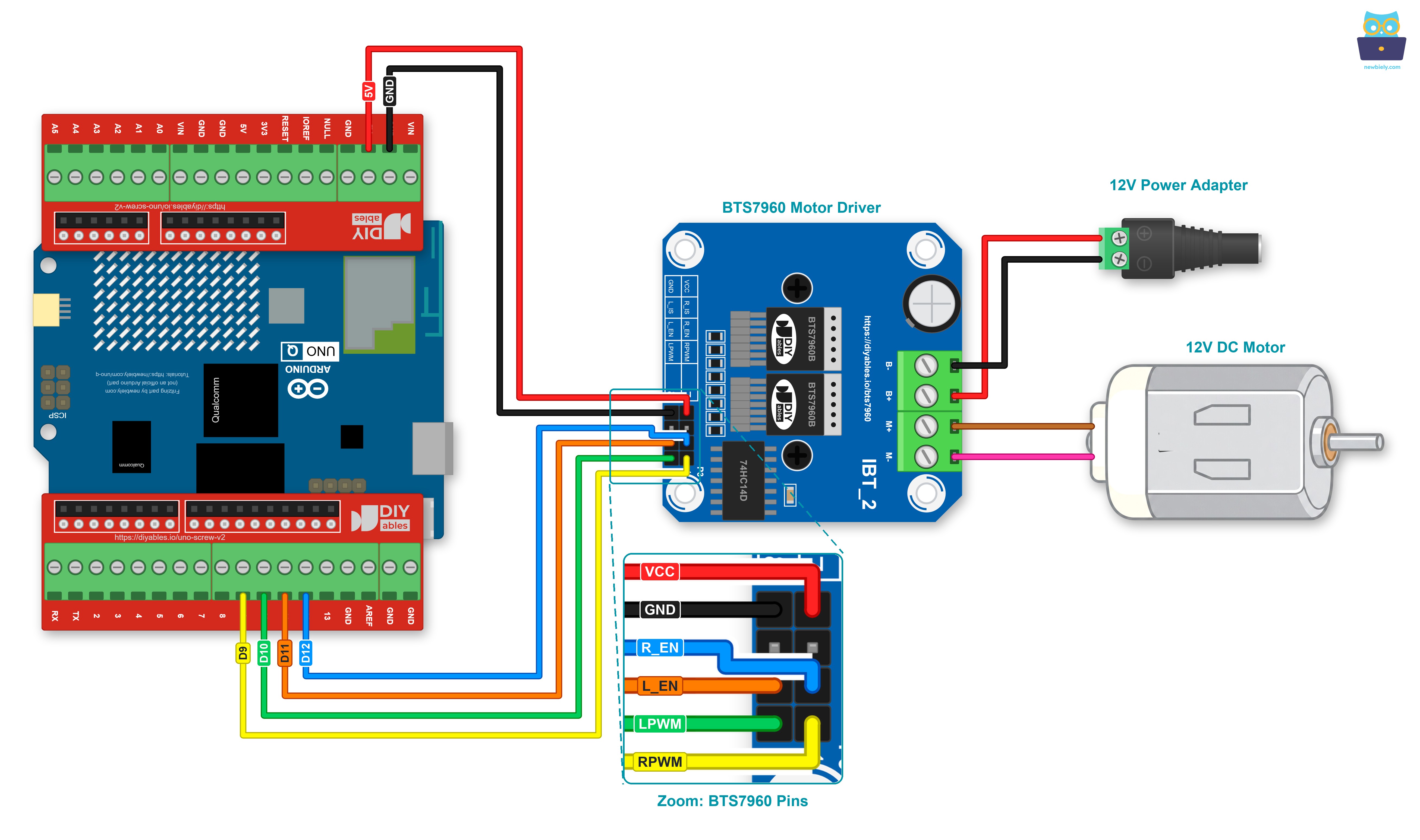
This image is created using Fritzing. Click to enlarge image
A few things to check before power goes on:
- Plug in the 12V adapter last, after every other wire is in place.
- Check plus and minus on the DC power jack: adapter + to B+, adapter - to B-. Plus and minus the wrong way round can destroy the driver.
- D9 and D10 carry the speed, so they must be PWM pins. R_EN and L_EN only switch on and off. If you move a wire, change the matching #define in the sketches.
How To Program For BTS7960
There is nothing to install. Four pins and two Arduino functions do all the work:
- Give the four pins names and make them outputs:
- Switch the driver on. Set both PWM pins to 0 first, so the motor does not jump:
- Run forward at a duty of 180 out of 255. LPWM stays at 0:
- Run in reverse at the same speed. RPWM stays at 0:
- Brake: both PWM pins at 0, while R_EN and L_EN stay HIGH:
- Coast: pull R_EN and L_EN LOW, and the driver lets go of the motor. Set them HIGH again before the next forward or reverse:
In the sketch, these lines live in four small helpers: bts_forward(), bts_reverse(), bts_brake() and bts_coast(). Each helper writes 0 to the unused PWM pin first, so the two sides are never driven together.
Arduino UNO Q Code
Who does what on the board:
- The STM32 MCU owns D9, D10, D11 and D12. PWM is real-time work, so the motor runs from here.
- The Qualcomm MPU with Debian Linux has nothing to do yet. It takes over in the Bridge section.
- The sketch repeats one test cycle: speed up forward, full speed, slow down, brake, half speed in reverse, coast.
Detailed Instructions
New to the Arduino UNO Q? Follow Getting Started with Arduino UNO Q once, so Arduino App Lab is ready.
- Signal wires: RPWM to D9, LPWM to D10, R_EN to D12, L_EN to D11, VCC to 5V and GND to GND, as in the diagram.
- Power wires, adapter unplugged: Put the motor wires into M+ and M-, and the DC power jack into B+ (plus) and B- (minus).
- Connect the board: Plug the Arduino UNO Q into your computer with the USB-C cable.
- Open Arduino App Lab and wait until it shows your UNO Q.
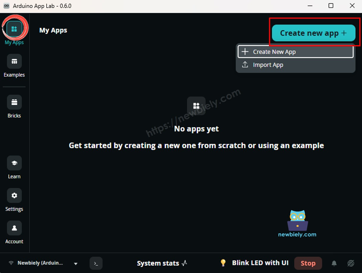
- New App: Click Create New App.
- Call it BTS7960Motor and click Create.
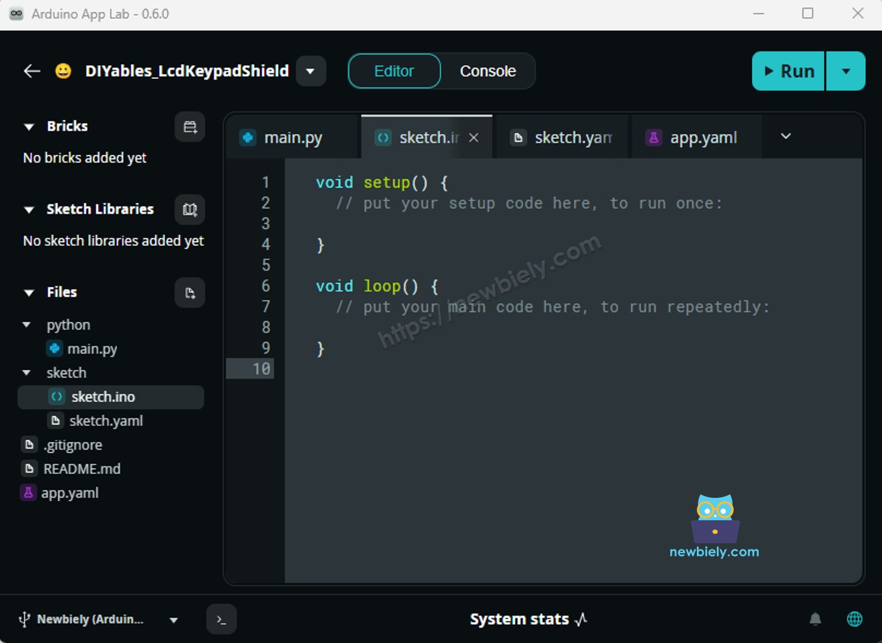
- Paste: Open sketch/sketch.ino, replace everything in it with the code above, and leave the other files alone.
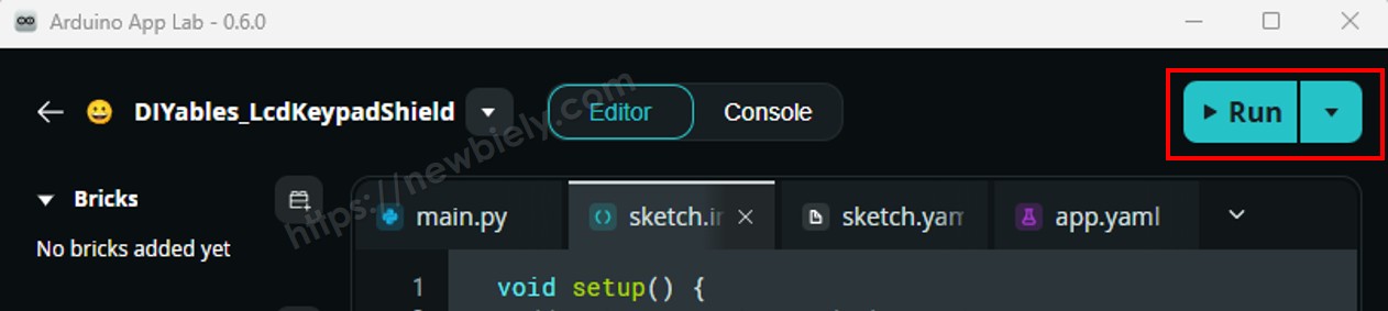
- Run: Click the Run button. The 12V adapter is still unplugged, so the motor stays still while the sketch uploads and starts.
- Power the motor: Now plug the 12V adapter into the DC power jack. Hold or clamp the motor, because a 12V gear motor has real force.
- Watch: Follow the console and the motor together. If "forward" turns the wrong way for your belt, swap the two motor wires on M+ and M-.
App Lab Console Output
Watch step 6 closely. After half speed in reverse, the motor slows down little by little, because the driver no longer holds it. In step 4 the driver holds the motor wires together, so the shaft is not free. At low duty you may also hear the motor hum or whine. That sound comes from the PWM signal and is normal.
Bridge: Linux + MCU
Now the conveyor gets a boss. A Python program on the Linux side decides when the belt starts, how fast it runs and when it stops. The MCU still makes every PWM pulse. Keep the same wiring.
- The BTS7960 stays wired to the MCU. Only the MCU writes to D9, D10, D11 and D12.
- The MCU offers these functions to Linux:
- forward / reverse: run the belt one way at the current speed
- brake: stop fast and hold
- coast: switch the driver off and let the belt roll out
- set_speed: a number from 0 to 255. A running belt changes at once, which is handy for slowing down while you load it
- get_state and get_speed: read-only, they answer with text like forward and 200
- The five functions that change pins are registered with Bridge.provide_safe(). The two read-only ones use plain Bridge.provide().
- ⚠️ The router keeps /dev/ttyHS1 (Linux) and Serial1 (MCU) for itself. They are RESERVED: your code must never open them.
The path of one command: Python calls set_speed or forward → the MCU changes RPWM / LPWM → the BTS7960 sends 12V power to the motor.
MCU Code (Bridge)
Python Code (Bridge)
The Python script plays one short work cycle of the belt: normal speed, a slow part for loading, a brake when the box is full, a short move back, and a pause.
Detailed Instructions
- Second App: Back in Arduino App Lab, click Create New App again. This time call it BTS7960Bridge.
- Sketch: Put the MCU code above into sketch/sketch.ino, then add one library to the App:
- Install the library: Click the Add sketch library button (the open book icon with a + sign) in the left sidebar.
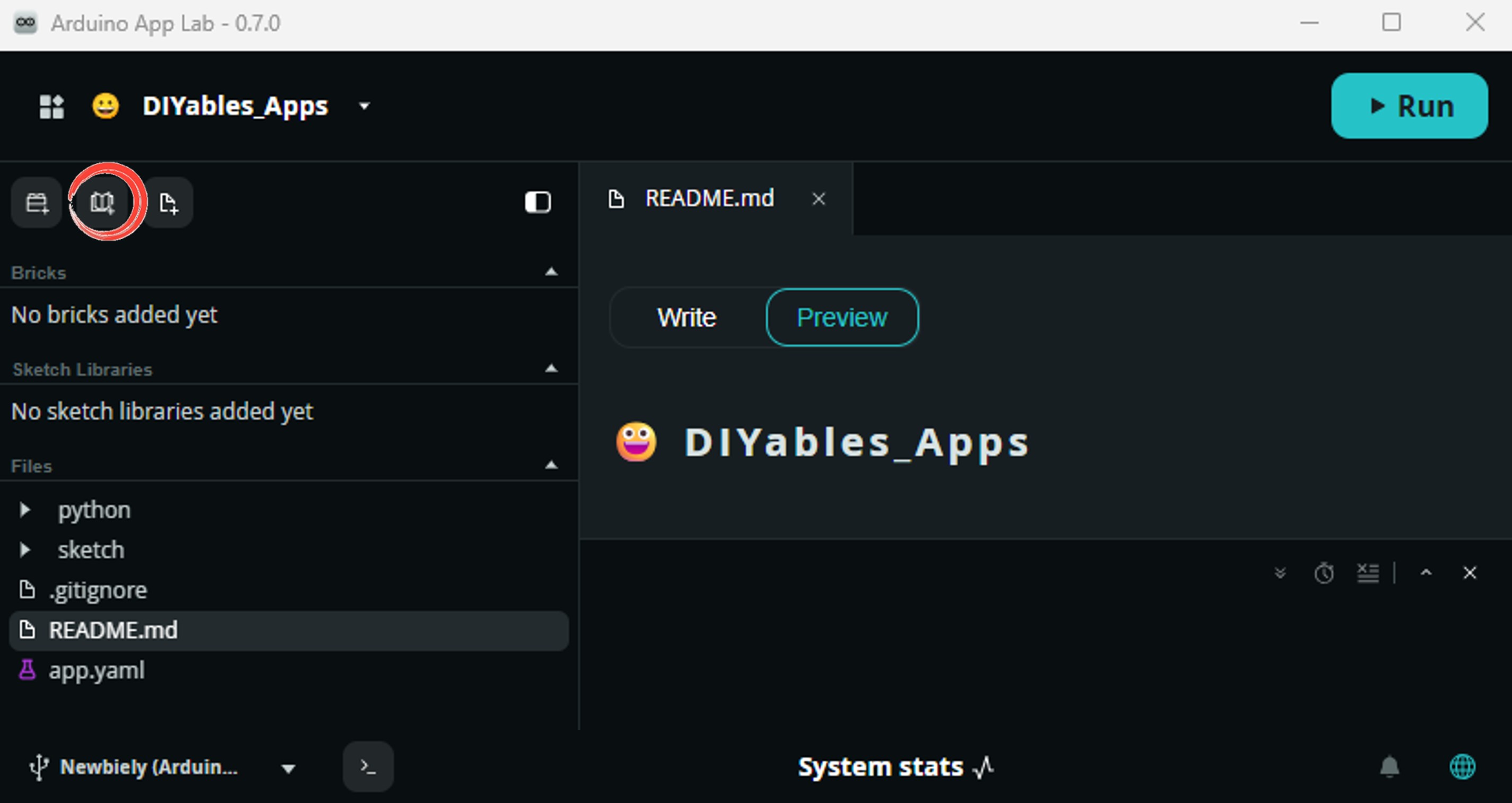
- Search for Arduino_RouterBridge created by Arduino and click the Install button.
- Python: Put the Python code into the App's Python file (same App, no second one).
- Run: Click the Run button, then plug in the 12V adapter.
- Compare the two consoles: The Python console says what Linux asked for. The MCU console says what the pins did.
App Lab Console Output
Look at the line at 11:40:25. The belt never stopped there. It only slowed from 200 to 90, because set_speed changes a running belt at once.
Telegram
A conveyor often stands far from your desk. With a Telegram bot you can start it, slow it down or stop it from your phone. Two safety rules are built into the script:
- Run timer: if the belt has run for 2 minutes with no new command, it brakes by itself and tells you. Change RUN_LIMIT if your belt needs longer runs.
- No sudden turn-around: if you send /reverse while the belt runs forward (or the other way), it brakes for half a second first. That is kinder to the motor, the gears and the driver.
| Command | What it does |
|---|---|
| /forward | run the belt forward at the set speed |
| /reverse | run the belt backward |
| /speed N | set the speed from 0 to 255, also while the belt runs |
| /brake | stop fast and hold |
| /coast | driver off, the belt rolls to a stop |
| /status | what the belt is doing right now |
No bot yet? Make one with How to Create a Telegram Bot and copy its token.
On the MCU side, nothing changes. The bot talks to the same Bridge sketch as above.
Python Code (Telegram)
Detailed Instructions
- Token: Paste the token from @BotFather into BOT_TOKEN.
- New Python, old sketch: In the BTS7960Bridge App, delete the old Python code and paste the bot code in its place.
- Run: Click the Run button and plug in the 12V adapter.
- Try it: Send /speed 150, then /forward. While the belt runs, send /speed 70 and watch it slow down. Finish with /brake.
- Check: Send /status at any time to see what the belt is doing.
App Lab Console Output


ArduinoBot
The last message came from the bot by itself. After /reverse, nobody sent anything for two minutes, so the run timer stopped the belt.
OpenClaw
You can adapt the OpenClaw to this tutorial by refering the instruction on Arduino Uno Q - OpenClaw Tutorial
Project Ideas
The BTS7960 is made for motors that move real loads. Some builds that use both halves of the Arduino UNO Q:
- Sorting Conveyor: Add a color sensor at the end of the belt. Python on Linux decides where each part goes, and the belt slows down while a small gate moves.
- Garden Cart Winch: A 12V winch motor pulls a cart up a slope. A soft ramp keeps the cable from jerking, and a limit switch stops it at the top.
- Gate Opener: A 24V gear motor opens a garden gate when you send a Telegram command, with a limit switch at each end.
- Feed Auger: A screw auger moves animal feed out of a tank. The Linux side runs it for a few seconds at set times each day.
- Heavy Robot Base: Use one BTS7960 per wheel motor for a robot that carries a load. The second driver needs two more PWM pins.
Challenge Yourself
Three tasks to test what you learned on this page:
- Easy: Change RAMP_DELAY in the first sketch so the motor needs about 5 seconds to reach full speed instead of about 1.5 seconds.
- Medium: Add a soft stop to the Bridge sketch: a slow_stop function that lowers the duty step by step in loop() with millis() (not delay()), then brakes.
- Advanced: Put an IR sensor at the end of the belt. When a part arrives, the MCU brakes at once, and the Telegram bot sends "part at the end of the belt" to your phone.