
ESP32 C3 Super Mini - Potentiometer LED
This tutorial shows you how to use the ESP32 C3 Super Mini with a potentiometer to change the brightness of an LED. Turn the knob and the LED fades up or down. It is a simple, fun project for beginners.
In this tutorial, you'll learn:
- How to wire a potentiometer and an LED to the ESP32 C3 Super Mini
- How to read the potentiometer with analogRead()
- How to scale the 0–4095 reading to a brightness from 0 to 255
- How to set the LED brightness with analogWrite()
- How to watch the values on the Serial Monitor
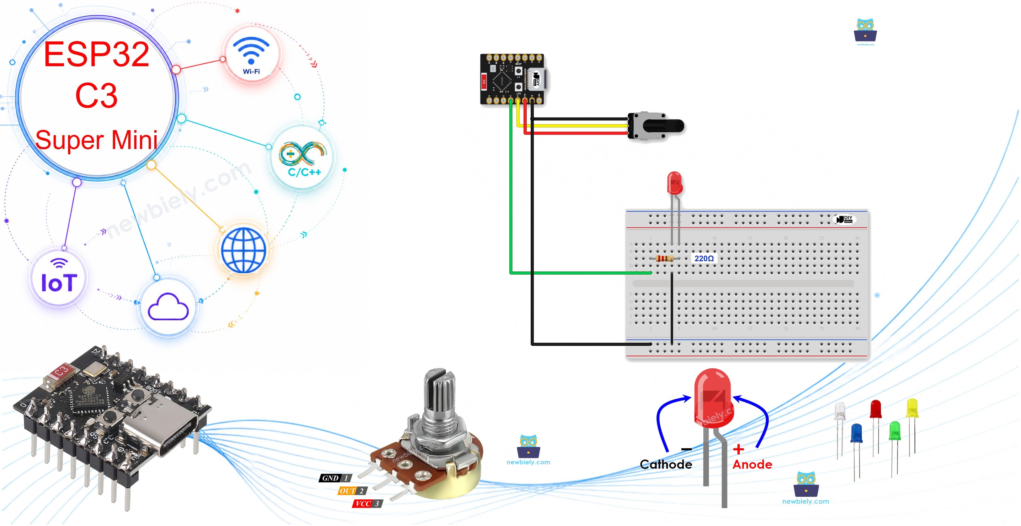
Hardware Preparation
Or you can buy the following kits:
| 1 | × | DIYables Sensor Kit (18 sensors/displays) |
Additionally, some of these links are for products from our own brand, DIYables .
Buy Note: Use the LED Module for easier wiring. It includes an integrated resistor.
Overview of LED and Potentiometer
A potentiometer is a knob that gives a changing voltage, and an LED is a small light whose brightness you can control.
Key Features:
- Potentiometer: Outputs a smooth voltage from 0V up to VCC as you turn it.
- LED: Fades smoothly with a PWM signal.
- Together: The knob sets the value, and the board turns that value into brightness.
Technical Specifications:
- Analog input range: 0V to 3.3V, read as 0 to 4095 (12-bit)
- PWM brightness range: 0 (OFF) to 255 (brightest)
- LED resistor: 220 ohm
Each part has its own tutorial with the pinout, how it works, wiring and code:
Pinout
Here are the pins you will connect in this project.
- Potentiometer VCC: connect to 3.3V
- Potentiometer GND: connect to GND (0V)
- Potentiometer Output: gives the voltage to the analog input pin
- LED Anode (+): the longer leg, controlled by the PWM pin through the resistor
- LED Cathode (-): the shorter leg, connects to GND
Wiring Diagram
The potentiometer uses three wires, and the LED uses two wires plus a resistor.
- Note: Power the potentiometer from 3.3V, never from 5V. The GPIO pins are 3.3V only.
- Note: The potentiometer output goes to GPIO4, because analog input works only on GPIO0 to GPIO4.
- Note: Always use the 220 ohm resistor with the LED, or the LED can burn out.
| Component Pin | ESP32 C3 Super Mini Pin |
|---|---|
| Potentiometer VCC | 3.3V |
| Potentiometer GND | GND |
| Potentiometer Output | GPIO4 |
| LED Anode (+) | GPIO3 (through 220 ohm resistor) |
| LED Cathode (-) | GND |
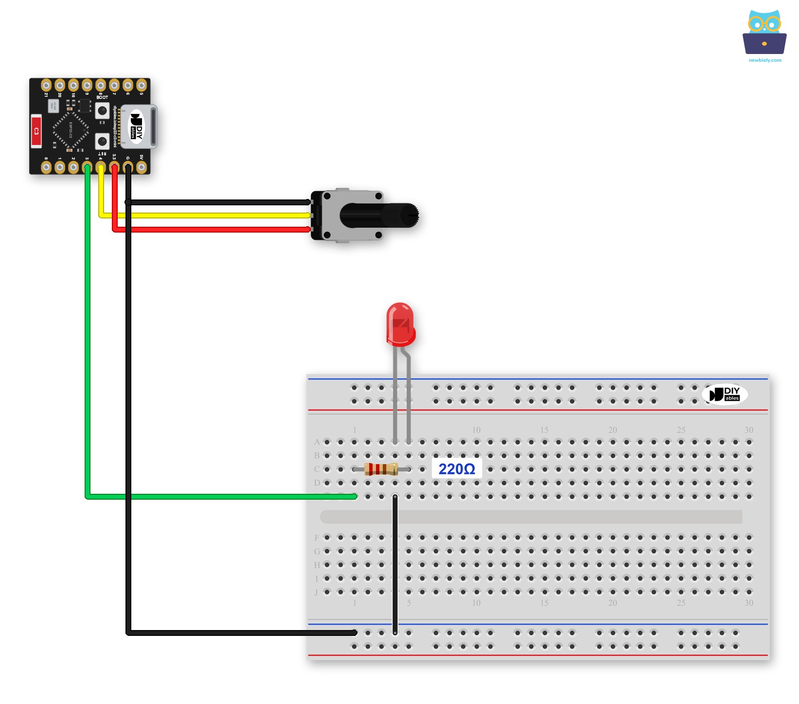
This image is created using Fritzing. Click to enlarge image
Here is the same wiring without a breadboard:
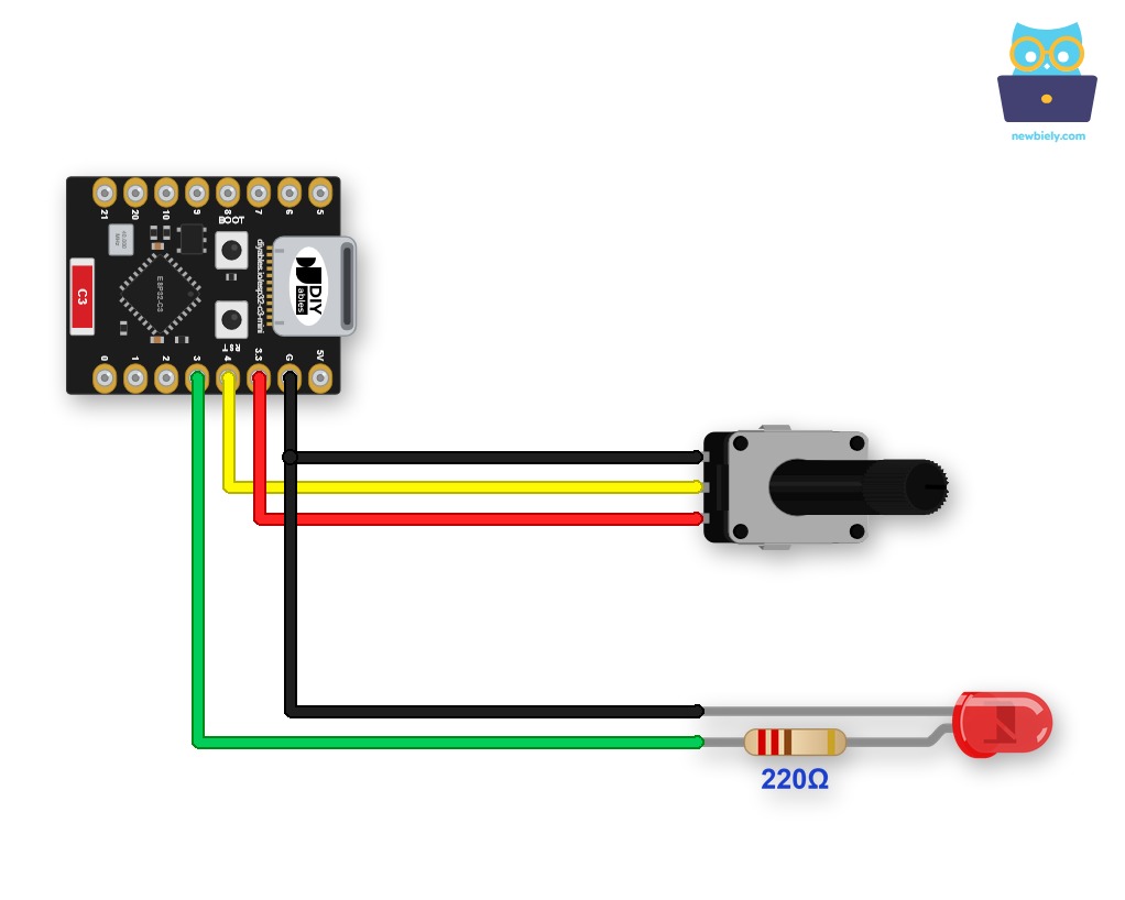
This image is created using Fritzing. Click to enlarge image
How To Program
The program does three small jobs, over and over.
- Read: reads the input on the analog pin (value between 0 and 4095)
- Scale: scales it to brightness (value between 0 and 255)
- Set: sets the brightness of the LED
ESP32 C3 Super Mini Code
The code below lets the potentiometer on GPIO4 control the LED on GPIO3.
What This Code Does:
- Starts Serial: opens the Serial Monitor at 115200 baud.
- Sets the ADC: analogSetAttenuation(ADC_11db) lets the pin read the full 0V to 3.3V range.
- Reads the knob: analogRead() gives a number from 0 to 4095.
- Changes the LED: map() turns that number into 0 to 255, and analogWrite() sets the brightness.
- Prints the values: shows the reading and the brightness every 100 ms.
Detailed Instructions
- New to ESP32 C3 Super Mini? Complete our Getting Started with ESP32 C3 Super Mini tutorial first to set up your development environment.
- Wire it up: Connect the potentiometer and the LED as shown above.
- Connect the board: Plug the ESP32 C3 Super Mini into your computer with a USB Type-C cable.
- Open the IDE: Copy the code above and paste it into Arduino IDE.
- Select the board: Make sure ESP32 C3 Super Mini is selected in Tools > Board.
- Select the port: Pick the COM port of your board in Tools > Port.
- Upload: Click the Upload button on Arduino IDE.
- Open Serial Monitor: Open it on Arduino IDE and set the baud rate to 115200.
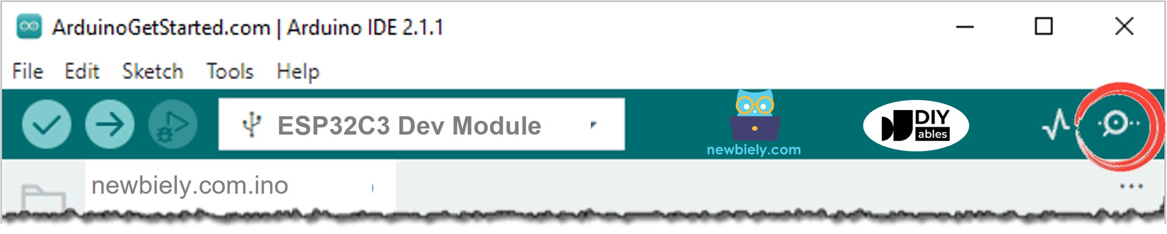
- Turn the knob: Rotate the potentiometer slowly.
- Watch the LED: See the LED fading as you turn.
- Check the result: See the values on the Serial Monitor. It looks like the below:
- Pro Tip: If the LED does not light up at all, turn the LED around. The longer leg must go to the resistor side, toward GPIO3.
Project Ideas
This same idea can control many real things.
- Desk Lamp Dimmer: Set the brightness of a small lamp with a knob.
- Night Light: Keep the LED at a soft level before going to sleep.
- Display Backlight Knob: Change how bright a small screen looks.
- Fan Speed Dial: Use the same code to set the speed of a small fan through a driver.
- Mood Light: Use three knobs to mix the colors of an RGB LED.
Challenge Yourself
Try these small upgrades to learn more about the ESP32 C3 Super Mini.
- Easy: Reverse the direction, so turning the knob up makes the LED dimmer.
- Easy: Print the brightness as a percentage from 0% to 100%.
- Medium: Start from a soft night-light level, so the LED never turns fully OFF.
- Medium: Average 10 readings to stop the LED from flickering.
- Advanced: Add a second LED on GPIO5 that fades in the opposite direction.
- Advanced: Add a second potentiometer on GPIO2 to control the second LED.