
ESP32 C3 Super Mini - 4-Channel Relay Module
Learn how to control multiple high-voltage devices using an ESP32 C3 Super Mini and a 4-channel relay module. This beginner-friendly tutorial shows you how to control pumps, fans, lights, and other appliances with your ESP32.
In this tutorial, you'll learn:
- What a 4-channel relay module is and how it works
- How to wire the 4-channel relay module to ESP32 C3 Super Mini
- How to program the ESP32 C3 Super Mini to control four relays
- Power supply requirements for relay modules
- Safety tips for working with high-voltage devices
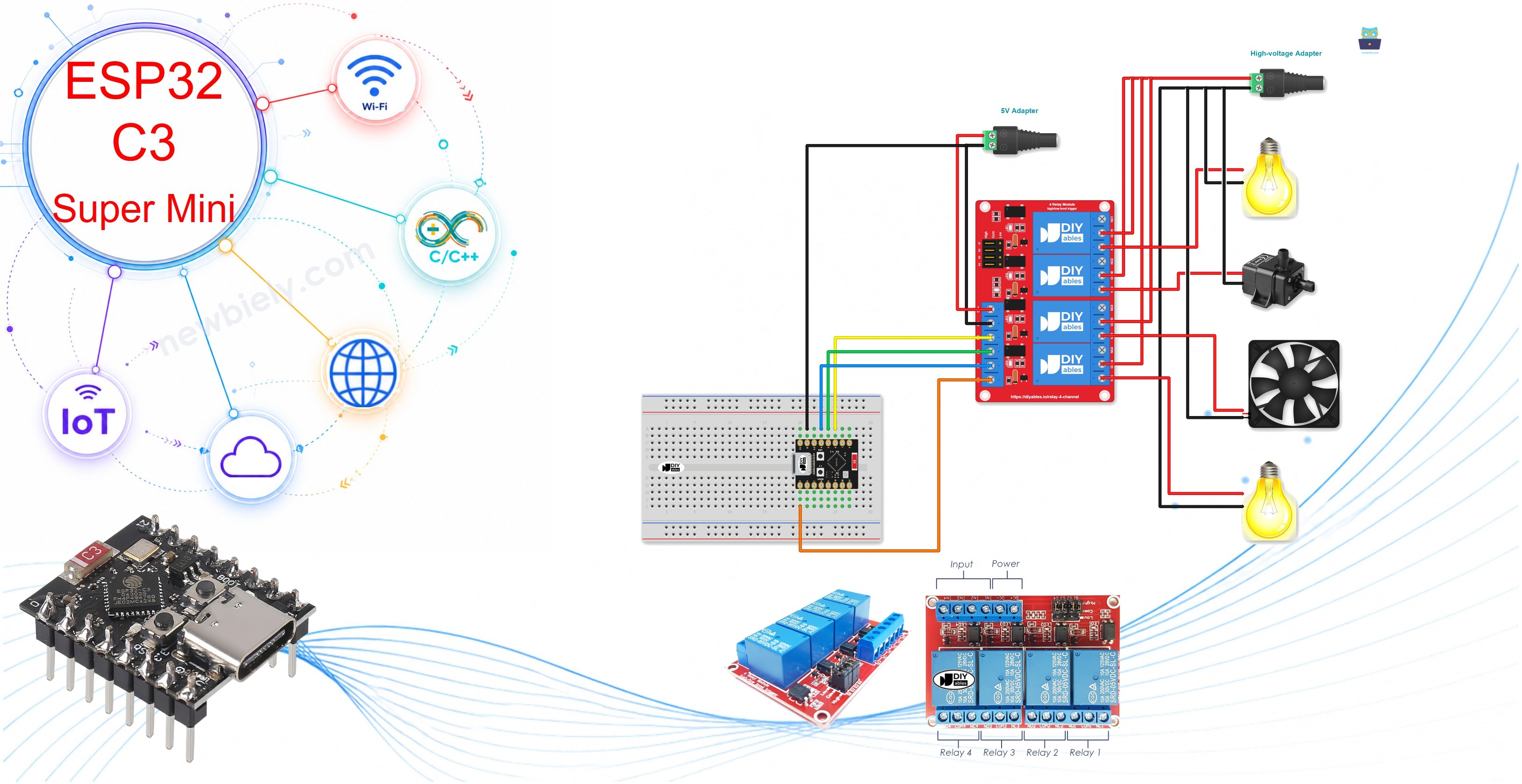
Hardware Preparation
Or you can buy the following kits:
| 1 | × | DIYables Sensor Kit (18 sensors/displays) |
Additionally, some of these links are for products from our own brand, DIYables .
Overview of 4-Channel Relay Module
A 4-channel relay module is a control board that contains four independent relays for switching high-voltage devices.
- Key Features:
- Controls up to four separate high-voltage devices (AC or DC)
- Each relay can handle loads up to 10A at 250VAC or 30VDC (typical)
- Operates with 5V logic signals from microcontrollers
- Onboard LED indicators show relay status
- Optocoupler isolation protects your ESP32 C3 Super Mini
- Configurable trigger modes (high/low) via jumpers
- Why Use It:
- Simplifies wiring compared to using four separate relay modules
- Cost-effective solution for multi-device control
- Perfect for home automation and IoT projects
- Beginner-friendly with clear pin labels
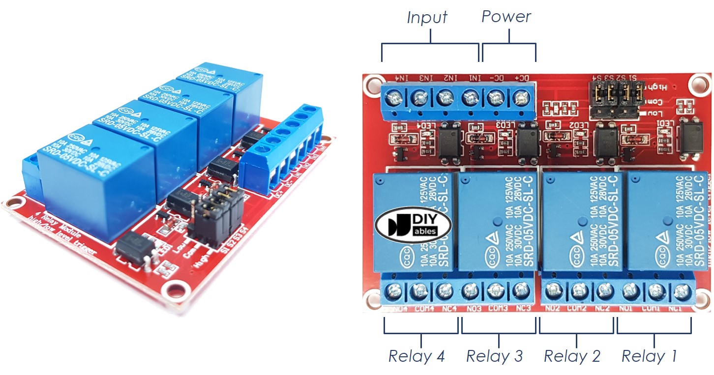
- DC+: Connect to 5V power supply (external adapter recommended)
- DC-: Connect to GND of power supply and ESP32 C3 Super Mini GND
- IN1: Control signal from ESP32 for relay 1
- IN2: Control signal from ESP32 for relay 2
- IN3: Control signal from ESP32 for relay 3
- IN4: Control signal from ESP32 for relay 4
- NC1, NO1, COM1: Relay 1 output (Normally Closed, Normally Open, Common)
- NC2, NO2, COM2: Relay 2 output (Normally Closed, Normally Open, Common)
- NC3, NO3, COM3: Relay 3 output (Normally Closed, Normally Open, Common)
- NC4, NO4, COM4: Relay 4 output (Normally Closed, Normally Open, Common)
The 4-Channel Relay Module Pinout
The pinout shows all connection points on the 4-channel relay module.
Power Pins:
Signal Pins (Control):
Output Pins (High-Voltage Connections):
To learn about connecting a relay to high-voltage devices and understanding the distinctions between normally closed and normally open, check out the ESP32 C3 Super Mini - Relay tutorial.
Additionally, the tutorial covers the 4 jumpers available on the relay module, which enable you to individually select between low trigger and high trigger settings for each relay.
Wiring Diagram
Follow this wiring guide to connect your ESP32 C3 Super Mini to the 4-channel relay module.
- Important Safety Notes:
- Never power the 4-channel relay module directly from the ESP32 5V pin - it draws too much current
- Always use an external 5V power supply for the relay module
- Double-check all high-voltage connections before applying power
- Keep high-voltage wiring separate from low-voltage control wiring
- 5V power adapter for the ESP32 C3 Super Mini (via USB or power jack)
- 5V power adapter for the 4-channel relay module
- High-voltage power source (12VDC, 24VDC, 120VAC, 220VAC, etc.) for the controlled devices
Power Supply Configuration:
You'll need multiple power sources for this project:
Wiring Diagram (Three Power Sources):
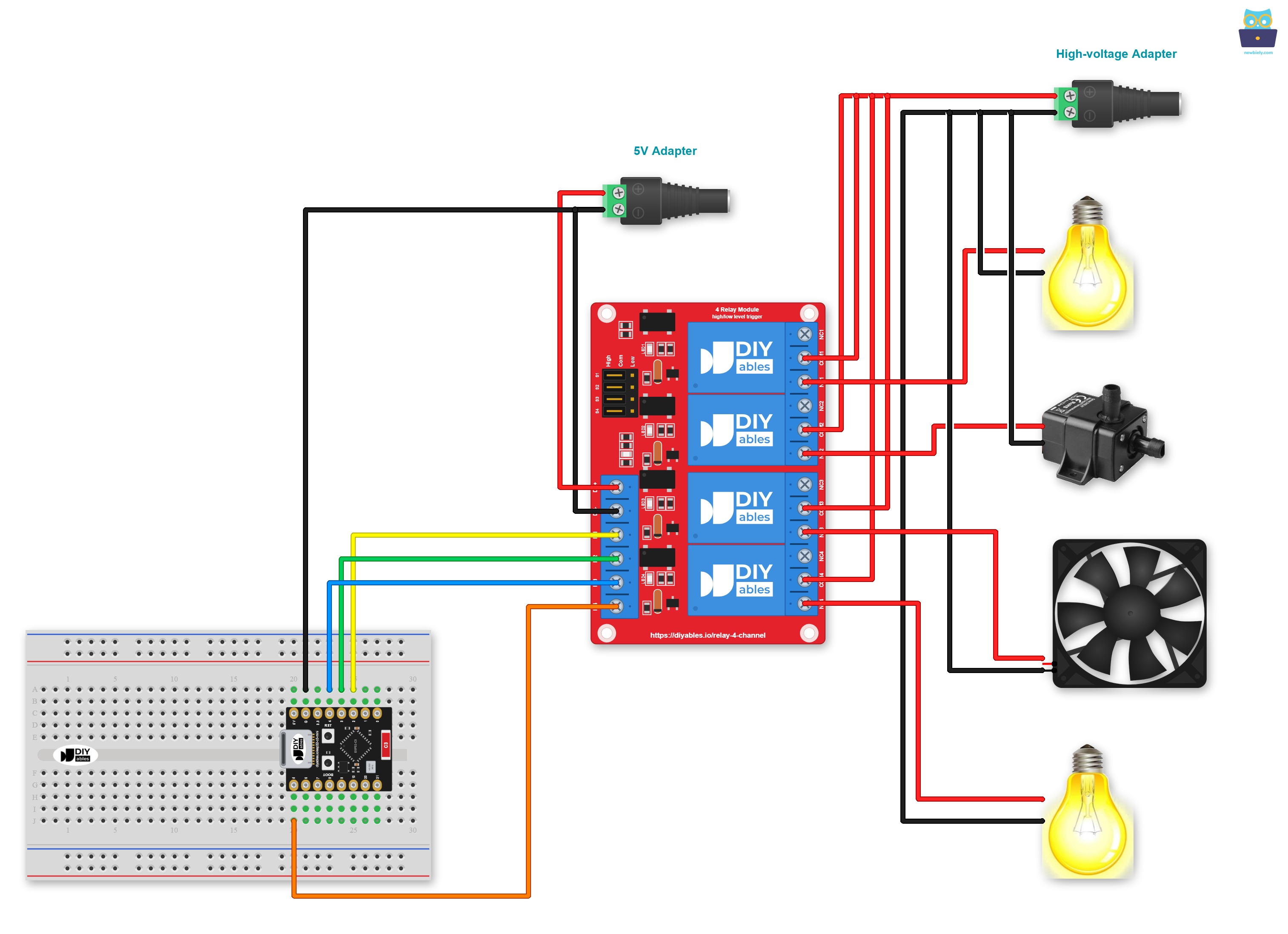
This image is created using Fritzing. Click to enlarge image
| 4-Channel Relay Module | ESP32 C3 Super Mini |
|---|---|
| DC+ | External 5V Power Supply (+) |
| DC- | External 5V Power Supply (-) AND ESP32 GND |
| IN1 | GPIO2 |
| IN2 | GPIO3 |
| IN3 | GPIO4 |
| IN4 | GPIO5 |
Simplified Wiring (Two Power Sources):
You can reduce the number of adapters by using one 5V power source for both the ESP32 C3 Super Mini and the 4-channel relay module:
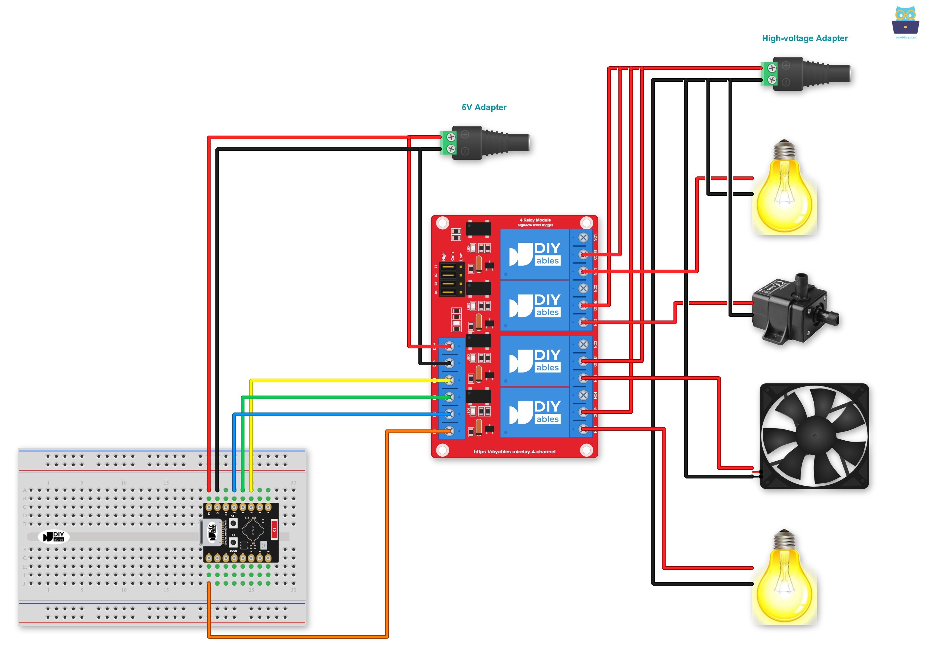
This image is created using Fritzing. Click to enlarge image
※ NOTE THAT:
If the four devices that are managed by a 4-channel relay module have the same voltage, then one high-voltage power adapter can be used for all of them. However, if the voltage is different for each device, then separate high-voltage power adapters must be used.
How To Program For 4-Channel Relay Module
Programming the ESP32 C3 Super Mini to control a 4-channel relay module is straightforward and uses basic digital output commands.
The code performs these tasks:
- Configures ESP32 pins as digital outputs for relay control
- Turns all four relays ON and OFF in sequence
- Provides serial feedback for monitoring relay states
- Creates a 2-second delay between state changes
Set pins to output mode:
Control relay states:
ESP32 C3 Super Mini Code
Detailed Instructions
- New to ESP32 C3 Mini? Complete our Getting Started with ESP32 C3 Mini tutorial first to set up your development environment.
- Check Environment Setup: If this is your first time using ESP32 C3 Super Mini, follow the software installation tutorial
- Wire the Components: Connect the ESP32 C3 Super Mini and 4-channel relay module according to the wiring diagram above
- Connect ESP32: Plug the ESP32 C3 Super Mini into your computer using a USB Type-C cable
- Open Arduino IDE: Launch the Arduino IDE software on your computer
- Select Board and Port: Choose ESP32 C3 Super Mini and select the correct COM port
- Copy the Code: Copy the provided code and paste it into Arduino IDE
- Upload the Code: Click the Upload button to transfer the code to your ESP32 C3 Super Mini
- Listen for Clicks: You should hear the relays clicking as they switch ON and OFF
- Check Serial Monitor: Open the Serial Monitor (baud rate 115200) to view the relay status messages
- Pro Tip: Label each relay and its controlled device to avoid confusion when building larger projects
Serial Monitor Output
Applications and Project Ideas
Use your ESP32 C3 Super Mini with a 4-channel relay module to build these practical projects:
- Home Automation System: Control lights, fans, heaters, and appliances remotely
- Greenhouse Controller: Automate irrigation pumps, grow lights, ventilation fans, and heating systems
- Aquarium Manager: Control filter pumps, air pumps, lights, and heaters on schedules
- Smart Garage: Operate door opener, lights, ventilation fan, and security system
- Tutorial Automation: Control power tools, dust collection, lighting, and equipment
- Energy Management: Schedule high-power devices to run during off-peak hours
Video Tutorial
Watch the video below for a visual walkthrough of this project.
Challenge Yourself
Take your ESP32 C3 Super Mini 4-channel relay skills to the next level with these challenges:
- Easy: Modify the code to control each relay independently with different timing patterns
- Easy: Add button inputs to manually control each relay channel
- Medium: Create a web interface to control all four relays from your smartphone
- Medium: Implement scheduled automation (turn relays ON/OFF at specific times)
- Advanced: Build a voice-controlled system using MQTT and Alexa or Google Home integration
- Advanced: Add current sensors to monitor power consumption of each controlled device