
ESP32 C3 Super Mini - Keypad 3x4
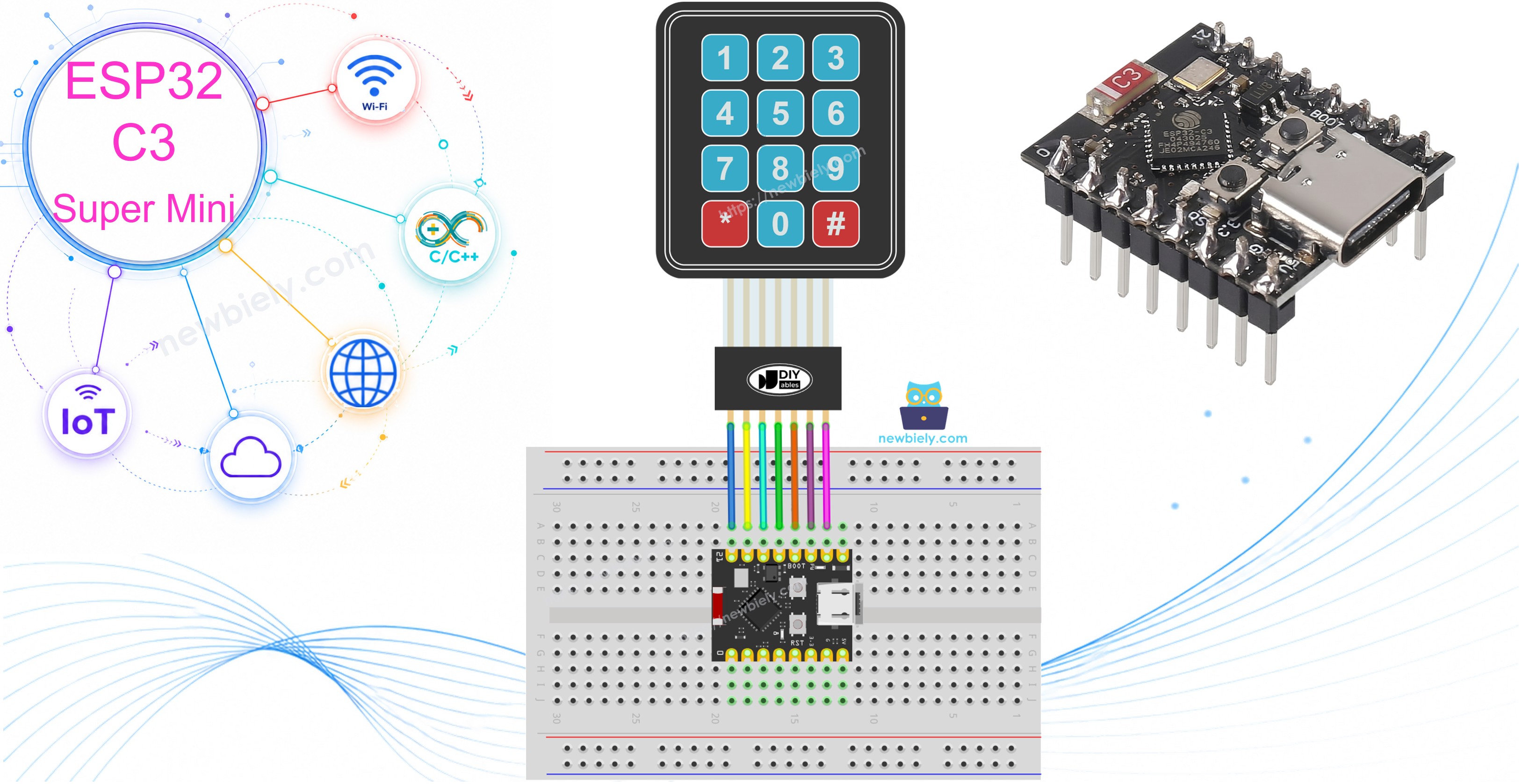
A 3x4 keypad gives your ESP32 C3 Super Mini 12 buttons but uses only 7 wires. It is the cheapest way to type numbers and PIN codes into a project. This ESP32 C3 Super Mini keypad tutorial shows the wiring and the code in small, simple steps.
In this tutorial, you'll learn:
- What a 3x4 membrane keypad is and how it works
- What the 7 keypad pins (R1-R4 and C1-C3) do
- How to wire a 3x4 keypad to the ESP32 C3 Super Mini
- How to print every pressed key on the Serial Monitor
- How to check a password with the "*" and "#" keys
Hardware Preparation
| 1 | × | ESP32 C3 Super Mini | |
| 1 | × | USB Cable Type-A to Type-C (for USB-A PC) | |
| 1 | × | USB Cable Type-C to Type-C (for USB-C PC) | |
| 1 | × | Keypad 3x4 | |
| 1 | × | Jumper Wires |
Or you can buy the following kits:
| 1 | × | DIYables Sensor Kit (18 sensors/displays) |
Additionally, some of these links are for products from our own brand, DIYables .
Overview of 3x4 Keypad
A 3x4 keypad is a thin membrane pad with 12 keys placed in 4 rows and 3 columns.
Key Features:
- 12 keys: The digits 0-9 plus the "*" and "#" keys.
- Only 7 pins: 4 row pins and 3 column pins.
- No power pin: The keypad needs no VCC and no GND.
- Matrix scanning: The board checks one row at a time to find the pressed key.
- Very thin: The flat membrane sticks on any flat surface.
Technical Specifications:
- Layout: 4 rows x 3 columns.
- Pins: 7 (R1, R2, R3, R4, C1, C2, C3).
- Logic level: Works with 3.3V, so it is safe for the ESP32 C3 Super Mini.
- Current: Almost zero. The GPIO pins drive it directly.
- Contact type: A simple open or closed switch under each key.
How It Works
Each key is a small switch that joins one row wire to one column wire.
- Idle: No row is joined to any column.
- Key pressed: That key's row and column touch each other.
- Scanning: The ESP32 C3 Super Mini pulls one row LOW, then reads the 3 column pins.
- Result: The row that was LOW plus the column that reads LOW tells you the exact key.
- Example: Pressing "5" joins row R2 to column C2.
The keypad library does all this scanning for you. You only call the getKey() function.
Pinout
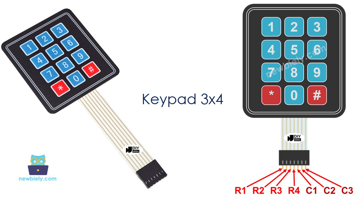
The 3x4 keypad has 7 pins in two groups.
- R1 pin: Row 1 - the top row of keys (1, 2, 3).
- R2 pin: Row 2 - the second row of keys (4, 5, 6).
- R3 pin: Row 3 - the third row of keys (7, 8, 9).
- R4 pin: Row 4 - the bottom row of keys (*, 0, #).
- C1 pin: Column 1 - the left column (1, 4, 7, *).
- C2 pin: Column 2 - the middle column (2, 5, 8, 0).
- C3 pin: Column 3 - the right column (3, 6, 9, #).
Wiring Diagram
Connect the 4 row pins and the 3 column pins to 7 free GPIO pins on the ESP32 C3 Super Mini.
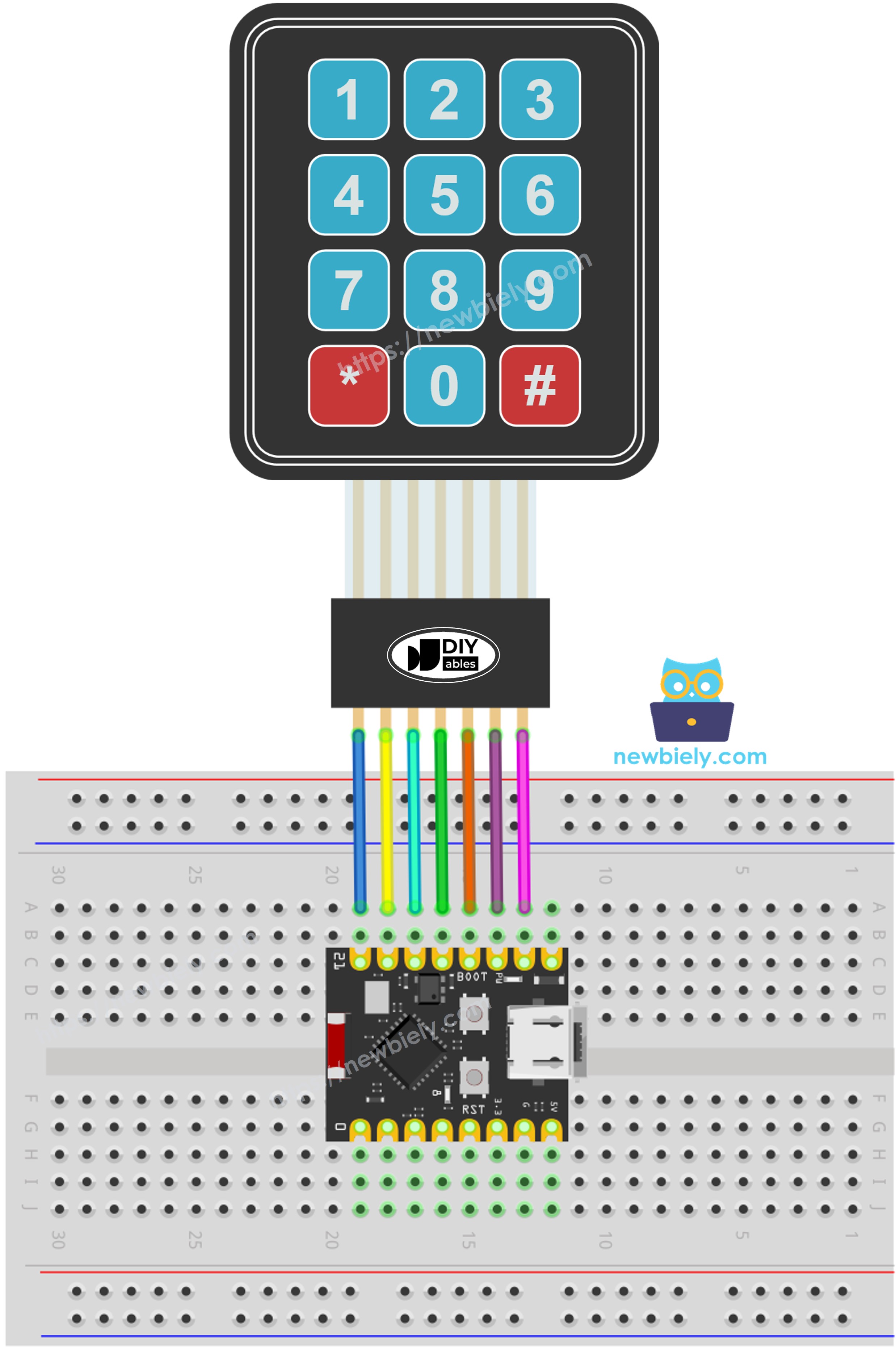
This image is created using Fritzing. Click to enlarge image
| Keypad Pin | ESP32 C3 Super Mini Pin |
|---|---|
| R1 | GPIO2 |
| R2 | GPIO3 |
| R3 | GPIO4 |
| R4 | GPIO5 |
| C1 | GPIO6 |
| C2 | GPIO7 |
| C3 | GPIO10 |
- Note: Use exactly these pins and this order. The code below uses the same pins.
- Note: The keypad has no VCC pin and no GND pin. Only 7 signal wires are needed.
- Note: Do not use GPIO8 (built-in LED), GPIO9 (boot pin), GPIO20 or GPIO21 (Serial Monitor UART).
- Note: Push each jumper wire in firmly. A loose wire makes a whole row or column stop working.
※ NOTE THAT:
A 3x4 keypad needs 7 pins, and the ESP32 C3 Super Mini has very few free pins. This wiring uses almost every free pin on the board. After this, only GPIO0 and GPIO1 are left, so plan ahead if your project also needs a display, a relay or a sensor.
WARNING
The ESP32 C3 Super Mini works at 3.3V logic only. Never connect a keypad pin to 5V. 5V on a GPIO pin can damage the board.
ESP32 C3 Super Mini Code - Read a Key
This first sketch prints the pressed key on the Serial Monitor.
What This Code Does:
- Sets GPIO2, GPIO3, GPIO4 and GPIO5 as the 4 row pins.
- Sets GPIO6, GPIO7 and GPIO10 as the 3 column pins.
- Scans the keypad in the background with the DIYables_Keypad library.
- Reads one key per loop with the getKey() function.
- Prints that key on the Serial Monitor at 115200 baud.
Detailed Instructions
- New to ESP32 C3 Super Mini? Complete our Getting Started with ESP32 C3 Super Mini tutorial first to set up your development environment.
- Wire the parts: Follow the wiring diagram above to connect the 3x4 keypad to the ESP32 C3 Super Mini.
- Connect the board: Plug the ESP32 C3 Super Mini into your PC with a USB Type-C cable.
- Open the IDE: Start the Arduino IDE software.
- Open Library Manager: Click the Libraries icon on the left bar of the Arduino IDE.
- Search for library: Type "DIYables_Keypad" in the search box.
- Install library: Look for the keypad library by DIYables.io, then click Install.
- Search for DIYables_Keypad created by DIYables.io and click the Install button.
- Select the board: Make sure ESP32 C3 Super Mini is selected in Tools > Board.
- Select the port: Pick the COM port of your board in Tools > Port.
- Copy the code: Copy the code above and paste it into the Arduino IDE.
- Upload the code: Click the Upload button in the Arduino IDE.
- Open Serial Monitor: Set the baud rate to 115200.
- Test it: Press a few keys on the keypad, one at a time.
- Check the output: Watch each key appear on the Serial Monitor.
- Pro Tip: If the wrong key is printed, swap the row wires and the column wires. Keypad ribbon cables are not always in the same order.
Line-by-line Code Explanation
The ESP32 C3 Super Mini code above contains line-by-line explanation. Please read the comments in the code!
Keypad and Password
A keypad is most useful when it checks a password, like a door lock or a PIN pad.
- Normal key (0-9): Add the key to the password the user is typing.
- "*" key: Clear the typed password and start again.
- "#" key: Compare the typed password with the saved one, then clear it.
- Match: Print ACCESS GRANTED, then run your own action.
- No match: Print ACCESS DENIED.
ESP32 C3 Super Mini Code - Keypad Password
This second sketch turns the keypad into a simple PIN pad.
What This Code Does:
- Saves a password in the sketch. The default one is 7890.
- Builds the typed password key by key in a String.
- Clears the typed password when you press "*".
- Checks the typed password when you press "#".
- Prints ACCESS GRANTED or ACCESS DENIED on the Serial Monitor.
Quick Steps (Password Example)
- Upload the code: Send the password sketch to your ESP32 C3 Super Mini.
- Open Serial Monitor: Set the baud rate to 115200.
- Try a wrong code: Press 1, 2, 3, 4, 5, 6 and then "#".
- Try the right code: Press 7, 8, 9, 0 and then "#".
- Check the output: Read the result on the Serial Monitor.
- Pro Tip: Press "*" any time you make a typing mistake. It clears the entry without checking it.
Application/Project Ideas
A 3x4 keypad is the input part of many small security and control projects.
- Door Lock: Open a relay or a solenoid lock when the right PIN is typed.
- Safe Box: Ask for a long key sequence before the lid can open.
- Alarm Keypad: Arm and disarm an alarm with a short code.
- Access Log: Save every key press with a time stamp on an SD card.
- Simple Calculator: Use 0-9 with "*" and "#" as the operation keys.
- Menu Input: Type a menu number to pick an item on an LCD screen.
Challenge Yourself
Try these small projects to practice with the 3x4 keypad and the ESP32 C3 Super Mini.
- Easy: Change the saved password to your own 6-digit code and test it.
- Easy: Blink the built-in LED on GPIO8 once for every key press.
- Medium: Show each typed digit as a star character on the Serial Monitor to hide the PIN.
- Medium: Lock the input for 30 seconds after three wrong tries.
- Advanced: Save the password in flash memory so it survives a power cut, and add a key sequence to change it.
- Advanced: Drive a relay and a solenoid lock so the correct PIN really opens a door.