
ESP32 C3 Super Mini - ACS712 Current Sensor
How much current does your motor really pull? Is your LED strip using more power than you think? An ACS712 module answers these questions in amps. In this tutorial, the ESP32 C3 Super Mini reads an ACS712 30A current sensor and prints the current of a 12V DC device, for example a DC motor. Near the end, we also measure AC current with a second sketch.
In this tutorial, you'll learn:
- What the ACS712 is and how it turns current into a voltage
- Why the ESP32 C3 Super Mini needs a voltage divider on the OUT pin
- How to put the sensor in series with a load
- How to find the zero point at start-up and print the DC current in amps
- How to measure AC current as an RMS value
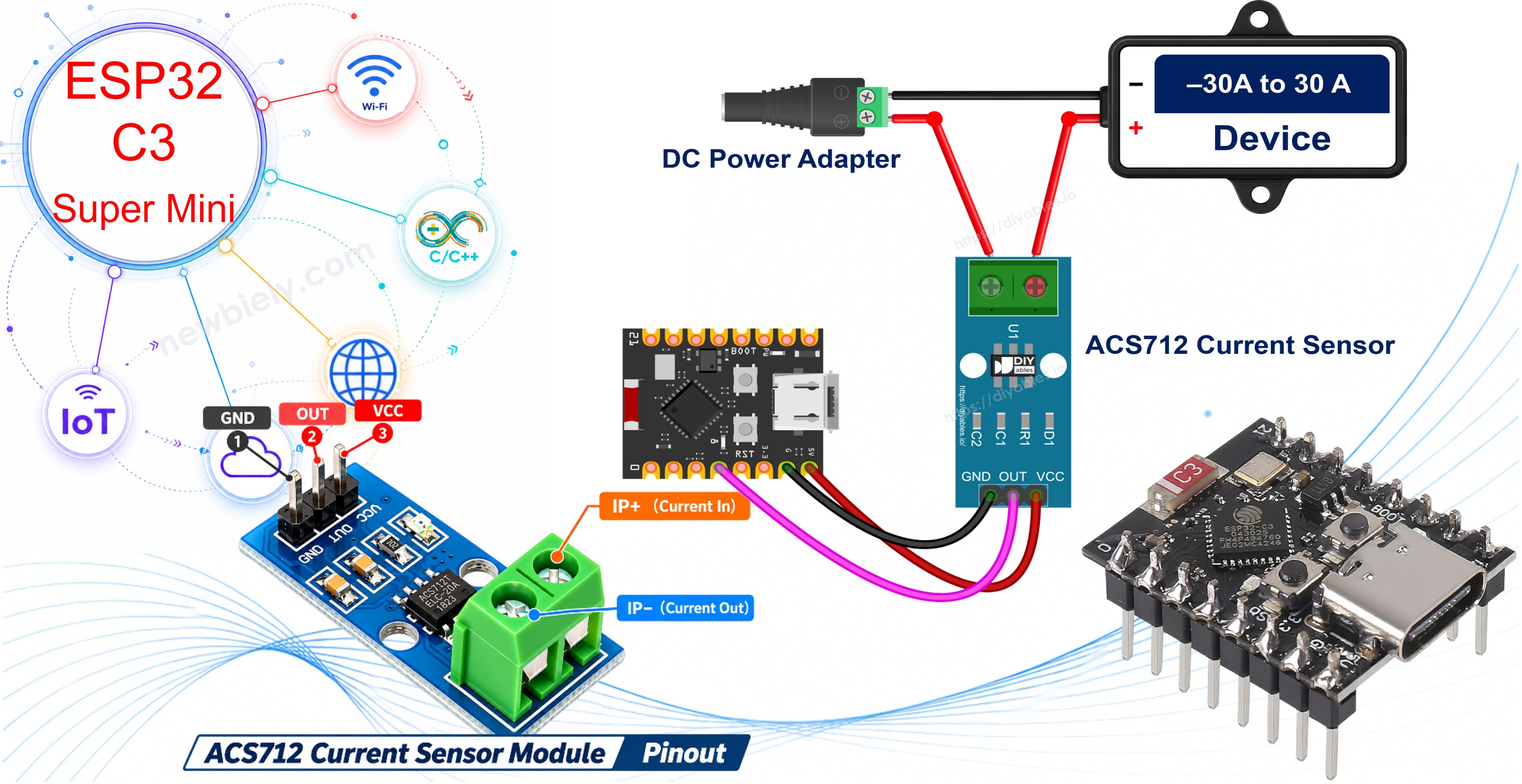
Hardware Preparation
Or you can buy the following kits:
| 1 | × | DIYables Sensor Kit (18 sensors/displays) |
Additionally, some of these links are for products from our own brand, DIYables .
Overview of ACS712 Current Sensor
The ACS712 is a Hall effect current sensor chip from Allegro. The load current goes through a thick copper path inside the chip. This current makes a small magnetic field, and a Hall sensor next to the copper turns that field into a voltage. The copper path and the sensor side are not connected (2.1 kV RMS isolation), so the load circuit stays separate from the ESP32 C3 Super Mini. The copper path is only about 1.2 mΩ, so it takes almost nothing from your circuit.
Key Features:
- Measures both DC and AC current
- Range of this module: −30A to +30A
- Supply voltage: 5V (4.5V to 5.5V). It does not work from 3.3V
- Output: an analog voltage. About 2.5V (half of VCC) at 0A
- Sensitivity: 66 mV for every 1A (30A version)
- Output is ratiometric: it follows the real 5V supply
- Bandwidth: 80 kHz
- Total output error: about ±1.5% at 25°C
Three versions, same pins:
| Version | Range | Sensitivity | Output at full current |
|---|---|---|---|
| ACS712 5A | ±5A | 185 mV/A | about 2.5V ± 0.93V |
| ACS712 20A | ±20A | 100 mV/A | about 2.5V ± 2.0V |
| ACS712 30A (this tutorial) | ±30A | 66 mV/A | about 0.52V to 4.48V |
If you use the 5A or 20A version, only change the sensitivity number in the code.
Why ACS712 is Great for Beginners:
- No library, just one analog pin
- The load side is isolated from the board
- Works with DC and AC loads
- Screw terminal for the load wires, no soldering
※ NOTE THAT:
The 30A version is made for bigger loads. Small currents (below about 0.5A) are hard to read, and a noise of ±0.05A to ±0.1A at 0A is normal. Motors, LED strips, lamps, heaters and chargers are good loads for it.
ACS712 Module Pinout
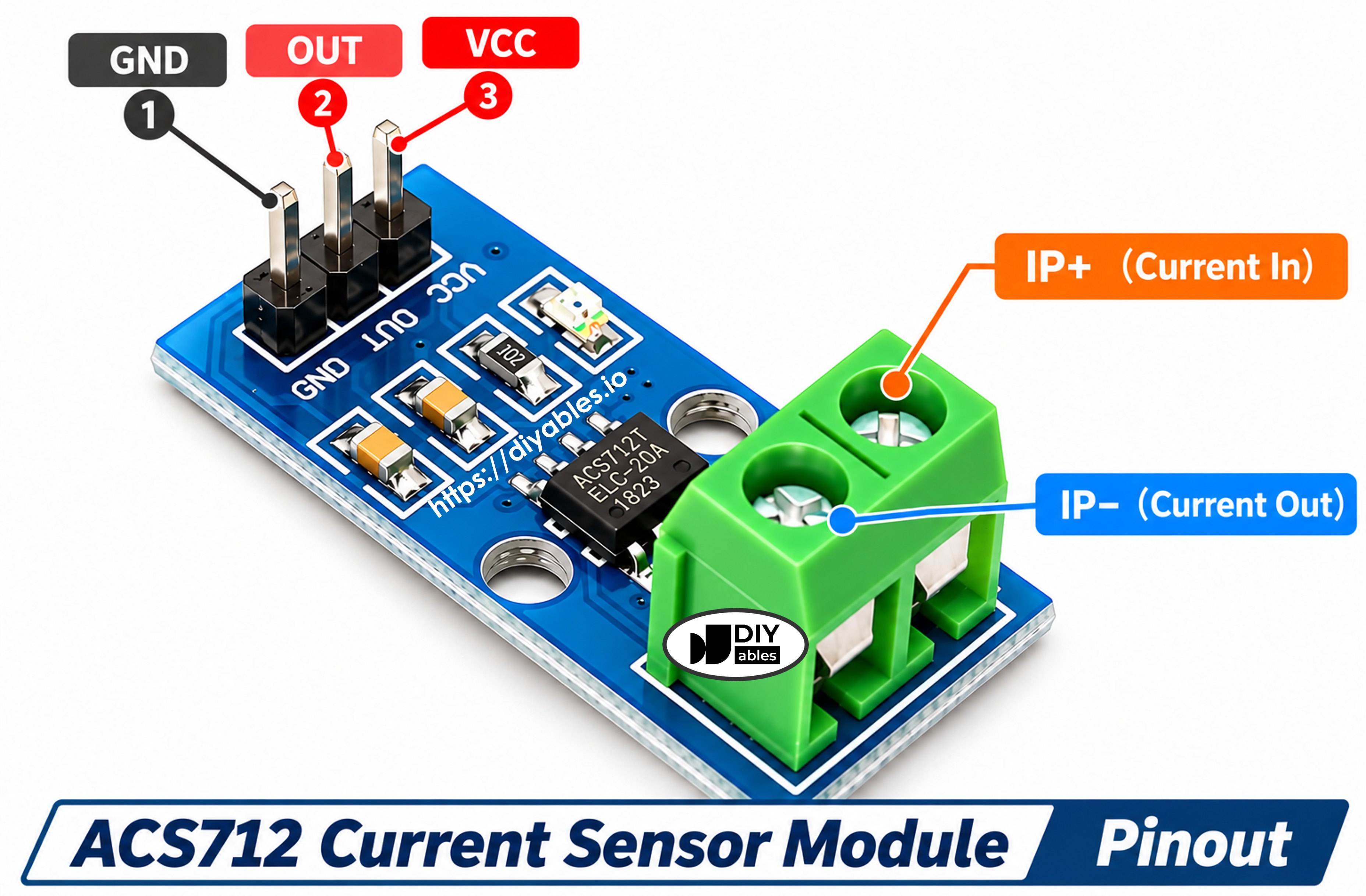
3-pin header (to the ESP32 C3 Super Mini):
- VCC pin: 5V power. Connect it to the 5V pin of the ESP32 C3 Super Mini
- GND pin: ground (0V)
- OUT pin: analog output voltage. It goes to GPIO3 through a voltage divider (see below)
2-pin screw terminal (to the load):
- IP+ and IP−: the current path. Put it in series with the load: cut one supply wire of the load and connect the two ends to the two screws
- Current that flows from IP+ to IP− gives a positive reading. The other way gives a negative reading
- Some modules do not print labels on the terminal
The module also has a small power LED.
How the Current Becomes a Number
At 0A, the OUT pin sits at about half of VCC. Current in one direction pushes OUT up, and current in the other direction pulls it down, by 66 mV per amp. So the formula is:
current (A) = (Vout − Vzero) / 0.066
- Vout: the voltage on the OUT pin now
- Vzero: the voltage on the OUT pin at 0A
Example: Vzero is 2.46V and Vout is 2.53V. Then the current is (2.53 − 2.46) / 0.066 ≈ 1.06A.
We do not just trust "2.5V" for Vzero. The 5V pin is often a bit lower than 5V, and every chip has a small offset. So the code measures Vzero by itself at start-up, while the load is OFF.
Wiring Diagram between ACS712 Current Sensor and ESP32 C3 Super Mini
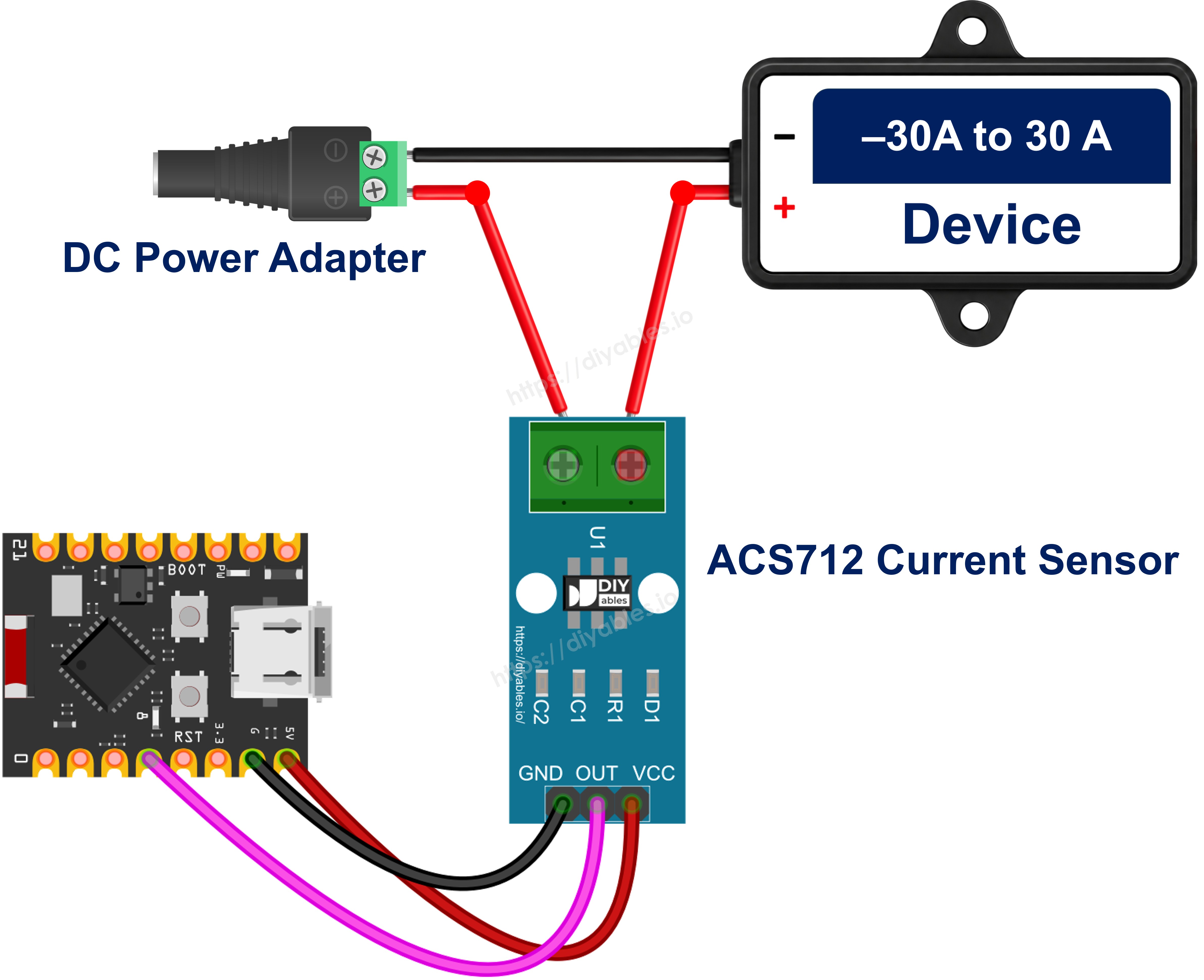
This image is created using Fritzing. Click to enlarge image
Sensor side:
| ACS712 Module Pin | Connects To |
|---|---|
| VCC | 5V pin of the ESP32 C3 Super Mini |
| GND | GND pin of the ESP32 C3 Super Mini |
| OUT | First 10kΩ resistor → GPIO3 |
| GPIO3 | Second 10kΩ resistor → GND |
Load side (12V DC device, such as a DC motor, LED strip or lamp):
| From | To |
|---|---|
| 12V adapter + (DC power jack +) | ACS712 IP+ |
| ACS712 IP− | DC device + wire |
| DC device − wire | 12V adapter − (DC power jack −) |
Why the voltage divider?
- The OUT pin can go up to about 4.5V, but ESP32 C3 pins accept only 3.3V
- Also, the ESP32 C3 ADC reads well only up to about 2.5V (with the default 11 dB setting)
- Two equal 10kΩ resistors cut the voltage in half: 4.48V → 2.24V, 2.5V → 1.25V, 0.52V → 0.26V
- All values now fit the ADC range, and the code multiplies the reading by 2 to get the real OUT voltage
- Note: GPIO3 is an ADC1 pin, so it still works if you add WiFi later. GPIO2, GPIO8 and GPIO9 are boot (strapping) pins, so we do not use them.
- Note: The 5V pin of the ESP32 C3 Super Mini has power only when the board runs from USB (or from a 5V supply on that pin).
- Note: The 12V side and the ESP32 C3 side do not share any wire. Do not connect the 12V ground to the board.
WARNING
Safety first. Mains AC (110V/220V) can kill. Practice with a low-voltage DC load like the 12V DC device in this tutorial. The screw terminal and the copper side of the module carry the full load voltage. Never touch them, or any load wire, while a mains circuit is live.
ESP32 C3 Super Mini Code - ACS712 DC Current
This sketch measures DC current, for example the current of a 12V motor or LED strip.
What the code does:
- Reads GPIO3 with analogReadMilliVolts(), which gives a calibrated voltage in mV
- Multiplies by 2 to undo the voltage divider
- At start-up, averages 1000 readings with the load OFF to find the zero voltage
- In the loop, averages 300 readings to reduce noise
- Turns the voltage into amps with (Vout − Vzero) / 0.066
- Prints the voltage and the current every 500 ms
Detailed Instructions
- New to ESP32 C3 Super Mini? Complete our Getting Started with ESP32 C3 Super Mini tutorial first to set up your development environment.
- Wire the circuit: Connect the sensor, the two resistors and the DC device as in the tables above. Keep the 12V adapter unplugged for now.
- Connect USB cable: Plug the board into your computer with a USB Type-C cable.
- Open Arduino IDE: Select the ESP32 C3 Super Mini board and its COM port.
- Copy the code: Paste the DC current code above into Arduino IDE. No library is needed.
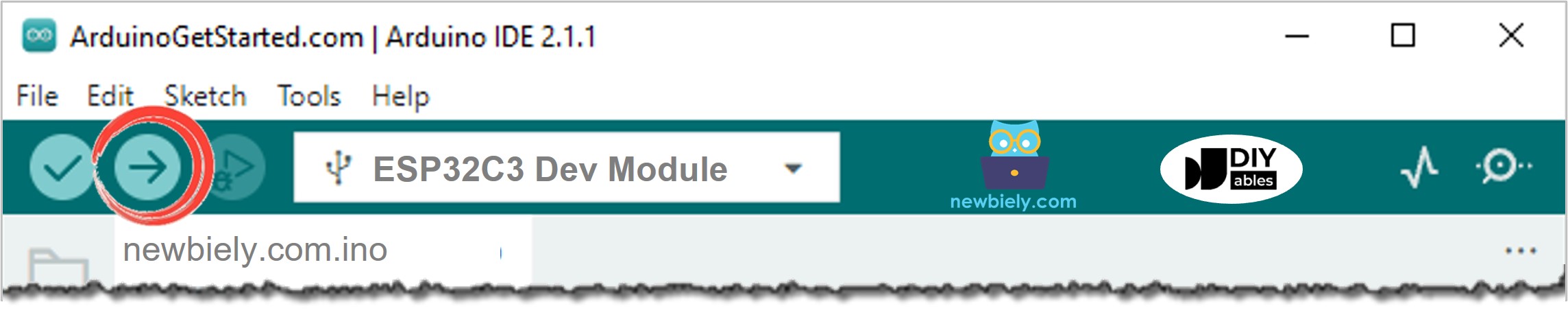
- Upload the code: Click the Upload button.
- Open Serial Monitor: Set the baud rate to 115200. Press the RST button on the board to see the start-up lines.
- Wait for calibration: The load must be OFF while "Calibrating..." is shown.
- Turn the load ON: Plug in the 12V adapter. The DC device turns on and the current goes up.
- Pro Tip: If the current is negative, the load wires on the screw terminal are swapped. Swap them, or just read the number without the minus sign.
This run uses a 12V DC motor as the DC device. The first lines show small noise around 0A. The 1.35A line is the motor start: a motor pulls more current for a moment when it starts to spin. Then it settles near 1A. The last line is after the adapter is unplugged again. Your numbers depend on your DC device and its load.
Line-by-line Code Explanation
The above ESP32 C3 Super Mini code contains line-by-line explanation. Please read the comments in the code!
Measuring AC Current
AC current changes direction 50 or 60 times per second. One reading can land anywhere on the wave, so it tells you nothing useful. Instead, we look at the wave over a short time and calculate the RMS value. RMS is the "effective" current, the number your AC meter shows.
How the sketch does it:
- Sample GPIO3 for 200 ms. That covers 10 cycles at 50 Hz or 12 cycles at 60 Hz
- For each sample, take (v − Vzero) and square it, so both halves of the wave count
- RMS current = sqrt(average of the squares) / 0.066
The wiring is the same. The load is now an AC device, and the screw terminal sits in series with one of its wires.
WARNING
Mains AC is dangerous. Only do this if you know how to work safely with mains wiring, use a closed enclosure, and never touch the module or the wires while they are live. If you are not sure, stop at the DC example.
What the code does:
- Finds the zero voltage at start-up, with the load OFF
- Takes as many samples as it can in 200 ms
- Calculates and prints the RMS current about every half second
Here a small heater of about 550W on 230V was turned on after the start. At 0A, the RMS value is never exactly zero, because noise also adds to the squares. A few hundredths of an amp is normal.
Applications and Project Ideas
Knowing the current helps you protect and understand your projects:
- A motor stall detector: a stuck motor pulls much more current, so stop it when the current jumps
- A power logger for a 12V LED strip or a battery charger
- An over-current alarm with a buzzer or an LED
- A "did it finish?" monitor for a washing machine or a 3D printer heater
- A WiFi energy dashboard that uses the built-in WiFi of the C3
- A solar panel monitor that shows how much current goes into a battery
Video Tutorial
Watch the video below for a visual walkthrough of this project.
Challenge Yourself
Try these ideas with your ESP32 C3 Super Mini and ACS712:
- Easy: Print the power in watts: multiply the current by 12 (the load voltage)
- Easy: Change the code for the ACS712 5A or 20A version by changing only the sensitivity
- Medium: Turn on an LED when the current goes above 1.5A
- Medium: Keep track of the highest current since start-up and print it too
- Advanced: Use a MOSFET module to cut the motor power when the current is too high
- Advanced: Add up current over time to show the energy used in watt-hours