
ESP32 C3 Super Mini - Motion Sensor - Servo Motor
Make a servo motor react when someone walks by. In this beginner tutorial, the ESP32 C3 Super Mini reads an HC-SR501 motion sensor and moves a servo motor. It is an easy first step into motion-triggered automation.
In this tutorial, you'll learn:
- How to connect an HC-SR501 motion sensor and a servo motor to the ESP32 C3 Super Mini
- How to set up the motion sensor before you use it
- How to rotate the servo motor to 90° if motion is detected
- How to rotate the servo motor back to 0° if motion is NOT detected
- How to check the events in the Serial Monitor
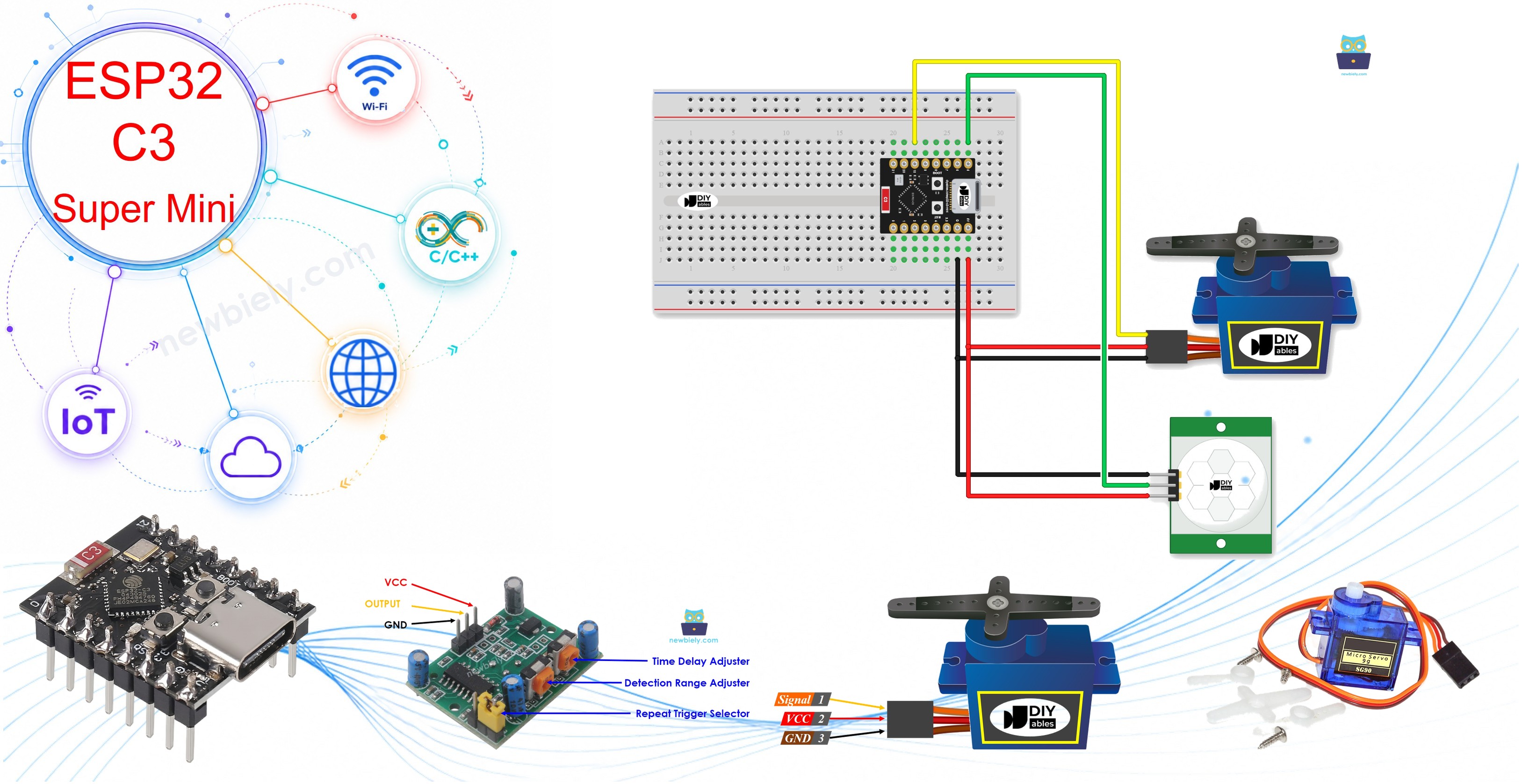
Hardware Preparation
Or you can buy the following kits:
| 1 | × | DIYables Sensor Kit (18 sensors/displays) |
Additionally, some of these links are for products from our own brand, DIYables .
Buy Note: For controlling multiple servo motors, use the PCA9685 16 Channel PWM Servo Driver Module to save MCU pins and simplify wiring.
Overview of Servo Motor and Motion Sensor
A motion sensor is a module that detects moving people and animals, and a servo motor is an actuator that turns to an exact angle.
Key Features:
- HC-SR501 motion sensor: gives a digital HIGH or LOW signal.
- Servo motor: moves to the angle set by your code.
- Together: a detected movement can open, close or point something by itself.
Technical Specifications:
- HC-SR501 power: 5V
- HC-SR501 detection range: up to 7 meters, adjustable
- Servo motor power: 5V
- Servo motor angle: 0° to 180°
New to these parts? These tutorials explain the pinout, how they work, and how to program them:
Pinout
Each part has three pins.
HC-SR501 motion sensor:
- VCC pin: connect to 5V.
- GND pin: connect to GND.
- OUTPUT pin: sends the HIGH or LOW signal to the board.
Servo motor:
- VCC pin: (red) connect to 5V.
- GND pin: (brown or black) connect to GND.
- Signal pin: (yellow or orange) receives the control signal from the board.
Wiring Diagram
Connect both parts to the ESP32 C3 Super Mini as shown below.
- Note: The HC-SR501 needs 5V on VCC. Its OUTPUT pin gives about 3.3V, so it is safe for GPIO5.
- Note: The 5V pin is fine for one small servo motor. Use an external power supply for a bigger servo motor.
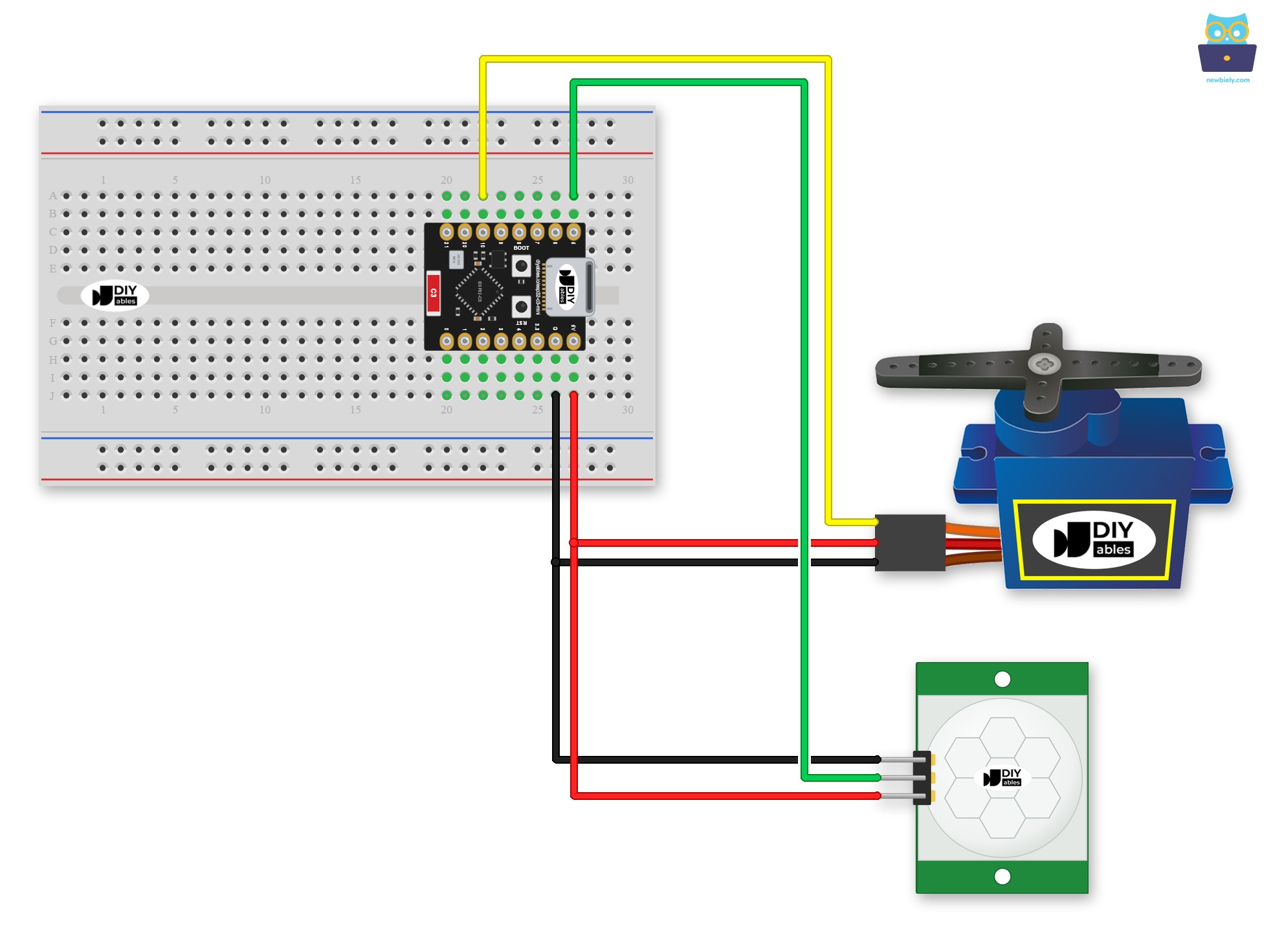
This image is created using Fritzing. Click to enlarge image
| HC-SR501 Pin | ESP32 C3 Super Mini Pin |
|---|---|
| VCC | 5V |
| GND | GND |
| OUTPUT | GPIO5 |
| Servo Motor Pin | ESP32 C3 Super Mini Pin |
|---|---|
| VCC (Red) | 5V |
| GND (Brown/Black) | GND |
| Signal (Yellow/Orange) | GPIO10 |
Initial Setting
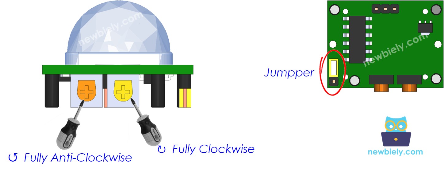
Set up the HC-SR501 like this before you run the code.
| Setting | Configuration |
|---|---|
| Detection Range Adjuster | Fully screw it in the clockwise direction. |
| Time Delay Adjuster | Fully screw it in the anti-clockwise direction. |
| Repeat Trigger Selector | Put jumper like the below image. |
ESP32 C3 Super Mini Code - Motion Sensor Controls Servo Motor
This code reads the motion sensor on GPIO5 and moves the servo motor on GPIO10.
What This Code Does:
- Starts Serial: opens the Serial Monitor at 115200 baud.
- Sets the pins: GPIO5 is an input and the servo motor is attached to GPIO10.
- Starts at 0°: the servo motor goes to its start angle in setup().
- Watches for changes: loop() compares the new sensor state with the last one.
- Moves the servo motor: it rotates to 90° or 0° and prints a message.
Detailed Instructions
- New to ESP32 C3 Super Mini? Complete our Getting Started with ESP32 C3 Super Mini tutorial first to set up your development environment.
- Wire it up: Connect the parts as shown in the wiring diagram above.
- Connect the board: Plug the ESP32 C3 Super Mini into your computer with a USB Type-C cable.
- Open the IDE: Open Arduino IDE on your computer.
- Select the board: Make sure ESP32 C3 Super Mini is selected in Tools > Board.
- Select the port: Pick the COM port of your board in Tools > Port.
- Install the library: Click the Libraries icon on the left bar, search for "ESP32Servo", and install the library by Kevin Harrington and John K. Bennett.
- Search for ESP32Servo created by Kevin Harrington,John K. Bennett and click the Install button.
- Copy the code: Copy the code above and paste it into Arduino IDE.
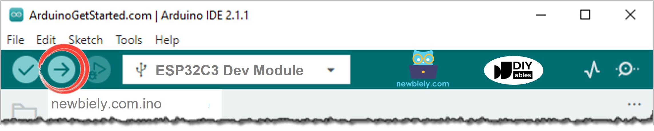
- Upload: Click the Upload button to send the code to the ESP32 C3 Super Mini.
- Open Serial Monitor: Set the baud rate to 115200.
- Test the sensor: Move your hand in front of the motion sensor.
- Watch the servo motor: See the change of the servo motor.
- Check the result: The Serial Monitor shows the events. It looks like the below:
- Pro Tip: If the servo motor shakes or the board restarts, the servo motor may need more current. Try an external power supply and connect its GND to the board's GND.
Code Explanation
Check out the line-by-line explanation in the comments of the source code!
Project Ideas
You can use this motion sensor and servo motor pair in many small builds.
- Automatic Pet Door: Open a small flap when your pet comes close.
- Touchless Trash Bin: Lift the lid when someone walks up to it.
- Halloween Prop: Move a scary figure when a visitor walks by.
- Air Vent Flap: Open a small vent when people are in the room.
- Model Gate: Raise a barrier when something moves near it.
Challenge Yourself
Try these small upgrades to your ESP32 C3 Super Mini motion sensor servo motor project.
- Easy: Change the target angle from 90° to 45° or 180°.
- Easy: Wait a few seconds before the servo motor returns to 0°.
- Medium: Add an LED on GPIO3 that shows when motion is detected.
- Medium: Count the motion events and print the total in the Serial Monitor.
- Advanced: Use a second motion sensor on GPIO6 to cover another direction.