
ESP32 C3 Super Mini - Measure Voltage
A voltage sensor lets your ESP32 C3 Super Mini measure voltages that are too high for its own pins. In this ESP32 C3 Super Mini voltage sensor tutorial, you will measure DC voltage from 0V to 16.5V and see the result on your computer. It only takes a few wires and no library.
In this tutorial, you'll learn:
- How a voltage sensor works
- What each voltage sensor pin does
- How to connect the voltage sensor to the ESP32 C3 Super Mini
- How to write code to measure voltage from the sensor
- How to check the result on the Serial Monitor
Hardware Preparation
| 1 | × | ESP32 C3 Super Mini | |
| 1 | × | USB Cable Type-A to Type-C (for USB-A PC) | |
| 1 | × | USB Cable Type-C to Type-C (for USB-C PC) | |
| 1 | × | Voltage Sensor | |
| 1 | × | Jumper Wires |
Or you can buy the following kits:
| 1 | × | DIYables Sensor Kit (18 sensors/displays) |
Additionally, some of these links are for products from our own brand, DIYables .
Overview of Voltage Sensor
A voltage sensor is a ready-made voltage divider that scales a high voltage down to a level the board can read.
Key Features:
- Built-in divider: Two accurate resistors are already on the module.
- Simple to use: Only one analog pin is needed.
- No library: A short formula gives you the real voltage.
Technical Specifications:
- Resistor R1: 30 KΩ
- Resistor R2: 7.5 KΩ
- Range with a 5V ADC reference: 0 to 25V DC
- Range with a 3.3V ADC reference: 0 to 16.5V DC
- Range on the ESP32 C3 Super Mini: 0 to 16.5V DC, because it uses the 3.3V reference
- ADC reading: analogRead() returns 0 to 4095 (12-bit)
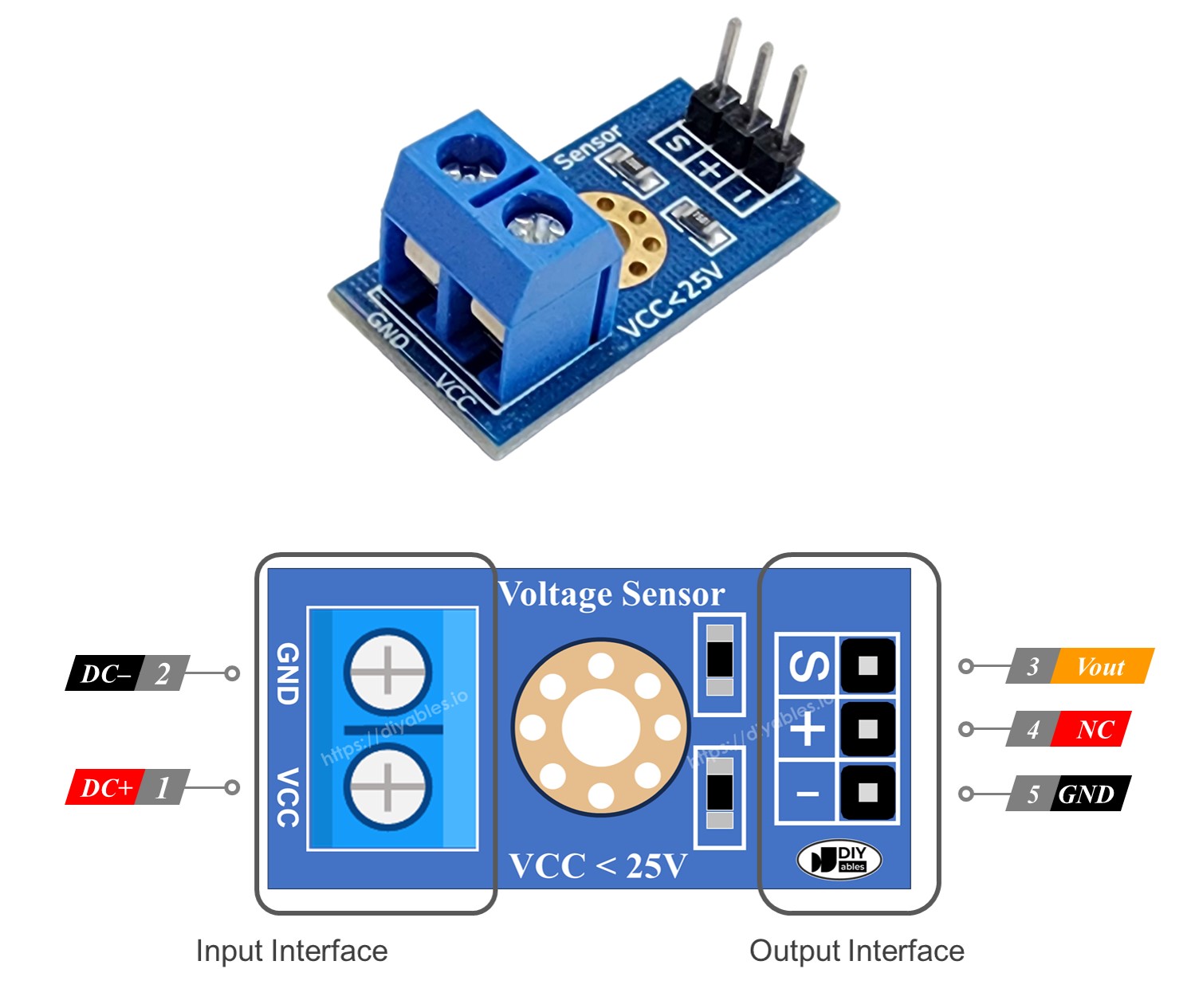
Pinout
The voltage sensor has two groups of pins.
Input Interface (connect where you need to measure voltage):
- VCC pin: Connect this positive pin to the higher voltage point.
- GND pin: Connect this negative pin to the lower voltage point.
Output Interface (connect to the ESP32 C3 Super Mini):
- Vout pin (S): Connect this pin to an analog pin of the ESP32 C3 Super Mini.
- NC pin (+): Do not connect this pin. Leave it free.
- GND pin (-): Connect this pin to the GND (0V) of the ESP32 C3 Super Mini.
Wiring Diagram
Connect the output side of the voltage sensor to the ESP32 C3 Super Mini as shown below.
- Note: Never measure more than 16.5V. A higher voltage puts more than 3.3V on GPIO4 and can damage the board.
- Note: Readings are most accurate up to about 12.5V, because the ESP32 C3 ADC reads well only up to about 2.5V on the pin.
- Note: Check the polarity on the input side. VCC goes to the higher voltage point and GND goes to the lower voltage point.
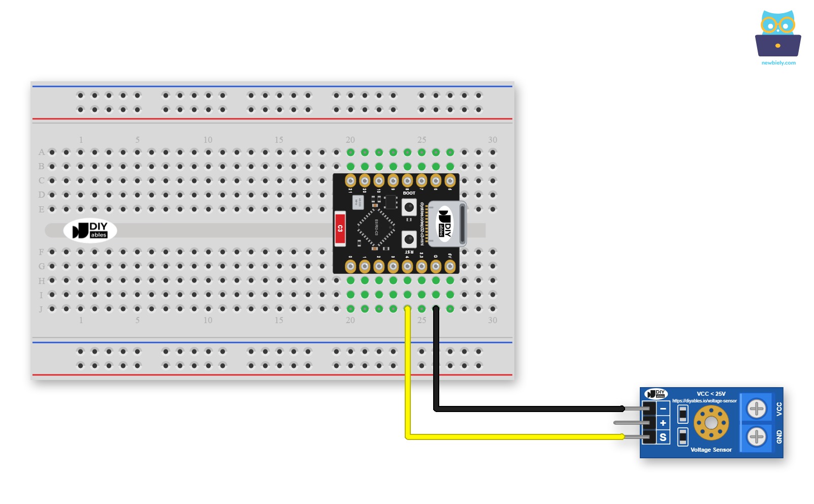
This image is created using Fritzing. Click to enlarge image
Here is the same wiring without a breadboard:
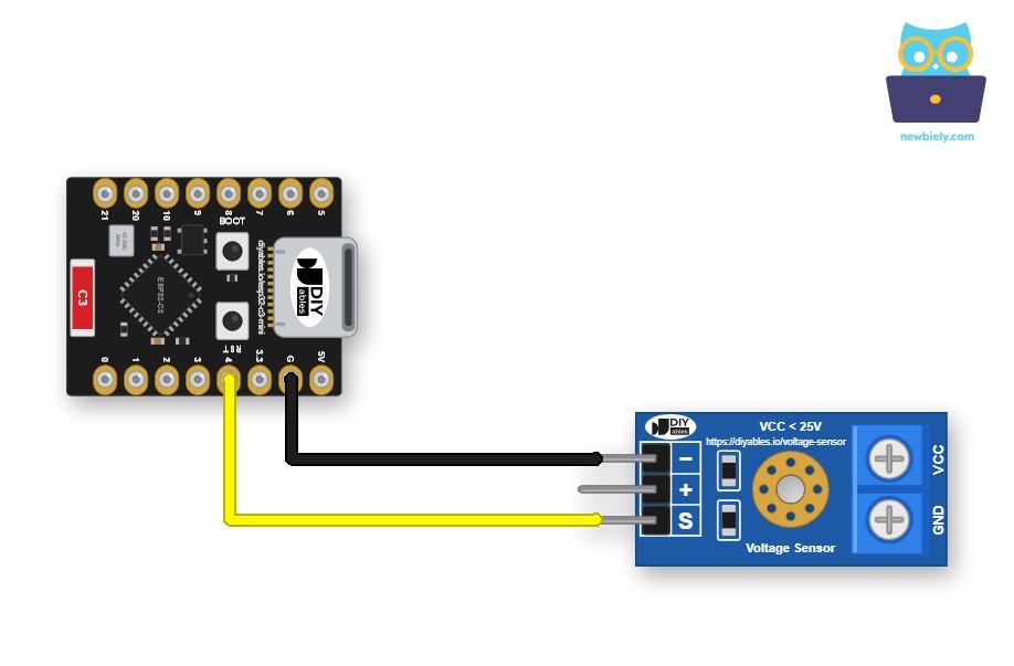
This image is created using Fritzing. Click to enlarge image
| Voltage Sensor Pin | ESP32 C3 Super Mini Pin |
|---|---|
| Vout (S) | GPIO4 |
| NC (+) | Not connected |
| GND (-) | GND |
ESP32 C3 Super Mini Code
This code reads the voltage sensor and prints the measured voltage to the Serial Monitor.
What This Code Does:
- Reads the pin: Gets a value from 0 to 4095 on GPIO4 with analogRead().
- Finds the pin voltage: Multiplies the value by 3.3, then divides by 4096.
- Finds the real voltage: Multiplies the pin voltage by (R1 + R2) / R2, which is 5 for this sensor.
- Prints the result: Shows the voltage with 2 decimal places, every 500 ms.
Detailed Instructions
Follow these bullets to get your ESP32 C3 Super Mini voltage sensor running.
- New to ESP32 C3 Super Mini? Complete our Getting Started with ESP32 C3 Super Mini tutorial first to set up your development environment.
- Wire the sensor: Connect the voltage sensor to the ESP32 C3 Super Mini as shown in the wiring diagram.
- Connect USB cable: Plug the board into your computer with a USB Type-C cable.
- Open Arduino IDE: Launch the Arduino IDE on your computer.
- Select the board: Make sure ESP32 C3 Super Mini is selected in Tools > Board, then choose its COM port.
- Copy the code: Paste the code above into the Arduino IDE.
- Upload the code: Click the Upload button to send the code to the ESP32 C3 Super Mini.
- Open Serial Monitor: Set the baud rate to 115200.
- Test it: Measure the 5V pin and then the 3.3V pin of the ESP32 C3 Super Mini. Connect the sensor's input VCC to the pin you test, and its input GND to GND.
- Check the results: Read the voltage on the Serial Monitor.
- Pro Tip: Compare the result with a multimeter. If it is a bit off, adjust the REF_VOLTAGE value in the code until they match.
※ NOTE THAT:
The measured value can change a little because the code uses 3.3V as the reference voltage. The real voltage may not be stable and can vary with the power supply.
Application Ideas
A voltage sensor is useful in many ESP32 C3 Super Mini projects that watch a power source.
- Battery Monitor: Check the voltage of a 12V battery.
- Low Battery Alarm: Warn the user when a battery runs low.
- Solar Panel Logger: Record the output of a small solar panel.
- Power Supply Checker: Test the output of a DC adapter.
- Charger Watcher: Follow the voltage of a battery while it charges.
Challenge Yourself
Try these ideas to grow your skills with the voltage sensor.
- Easy: Print the raw analogRead() value next to the measured voltage.
- Easy: Change the delay so the voltage prints once per second.
- Medium: Average 10 readings before printing to make the value steady.
- Medium: Print a warning when the voltage goes below a value you choose.
- Advanced: Add an LED on GPIO3 that turns on when the voltage is too low.