
ESP32 C3 Super Mini - LED RGB
This tutorial shows you how to control an RGB LED with the ESP32 C3 Super Mini so it can show any color. You will mix red, green and blue using PWM signals. It is a simple and fun first color project for beginners.
In this tutorial, you'll learn:
- What an RGB LED is and how it mixes colors
- How to read the RGB LED and RGB LED module pinout
- How to wire an RGB LED to the ESP32 C3 Super Mini
- How to turn a color code into R, G and B values
- How to write code that changes the LED color, with a short helper function
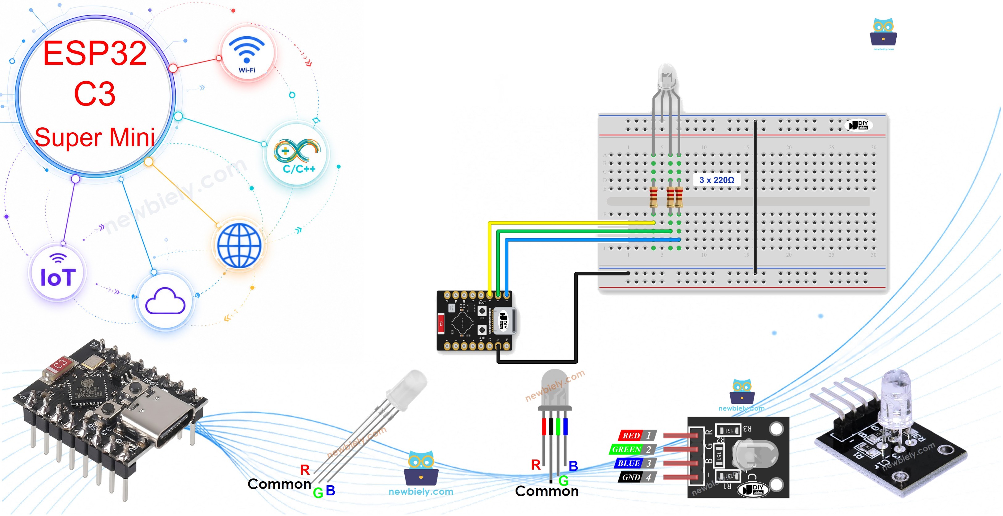
Hardware Preparation
Or you can buy the following kits:
| 1 | × | DIYables Sensor Kit (18 sensors/displays) |
Additionally, some of these links are for products from our own brand, DIYables .
Overview of RGB LED
An RGB LED is a light that shows any color by mixing the 3 basic colors: red, green and blue.
Key Features:
- Three LEDs in one: A red, a green and a blue LED sit inside a single case, so it looks like one LED
- Any color: Mixing the three basic colors gives you almost any color you want
- PWM control: The brightness of each color is set by a PWM signal
Technical Specifications:
- Pins: 4 pins (R, G, B and Common)
- Color value range: 0 to 255 for each color element
- Total colors: 256 x 256 x 256 combinations
- Type used here: Common cathode
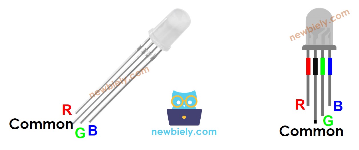
RGB LED Pinout
An RGB LED has four pins:
- R (red) pin: Controls the red color element
- G (green) pin: Controls the green color element
- B (blue) pin: Controls the blue color element
- Common (Cathode-) pin: Connect this pin to GND (0V)
RGB LED Module Pinout
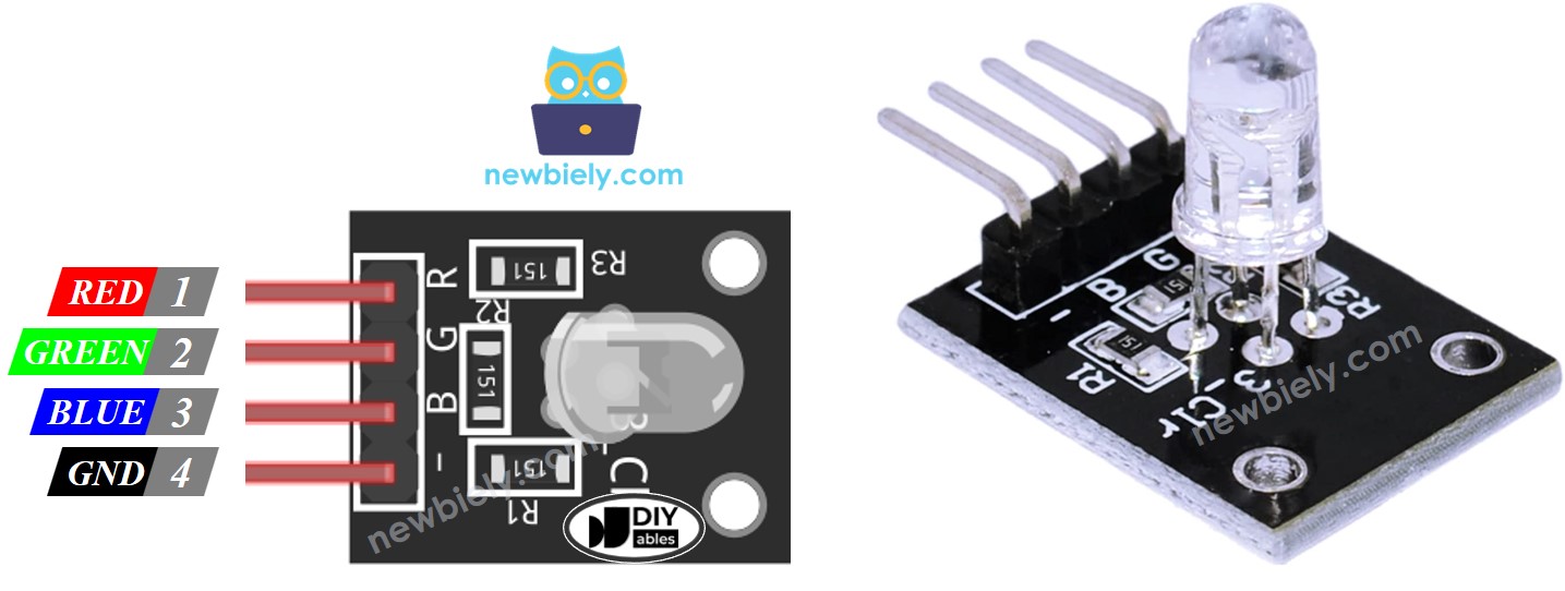
A bare RGB LED needs current-limiting resistors, and that makes the wiring harder. An RGB LED module already has these resistors built in.
The RGB LED module also has four pins:
- Common (Cathode-) pin: Connect this pin to GND (0V)
- R (red) pin: Controls red
- G (green) pin: Controls green
- B (blue) pin: Controls blue
※ NOTE THAT:
According to the common pin, there are two types of LED: common anode and common cathode. This tutorial uses a common cathode LED.
How RGB LED Works
Every color is a mix of three color elements: Red (R), Green (G) and Blue (B).
- Value range: Each color element goes from 0 to 255
- Total colors: The three values together give 256 x 256 x 256 colors
- PWM signal: Send a PWM signal to the R, G and B pins, and the LED shows a matching color
- Duty cycle: Change the duty cycle from 0 to 255 to get any color
- Matching values: The R, G and B values are the PWM duty cycle values on the R, G and B pins
Wiring Diagram between RGB LED and ESP32 C3 Super Mini
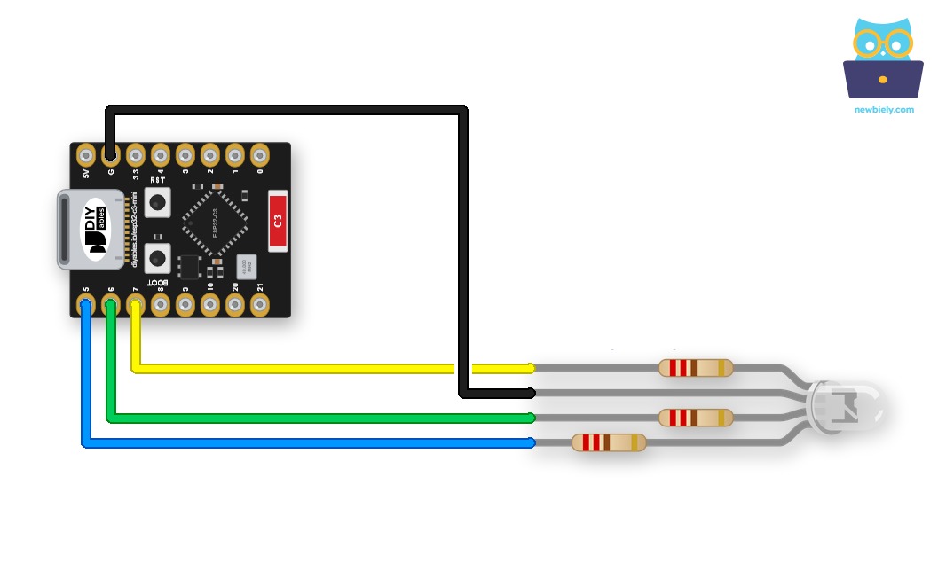
Connect the three color pins to three GPIO pins and the common pin to GND.
- Note: A bare RGB LED needs one current-limiting resistor on each color pin (R, G and B)
- Note: The RGB LED module already has these resistors, so you can wire it directly
- Note: Check that your LED is common cathode. A common anode LED is wired and coded differently
Wiring diagram between ESP32 C3 Super Mini and RGB LED:
| RGB LED Pin | ESP32 C3 Super Mini Pin |
|---|---|
| R | GPIO7 (through a resistor) |
| G | GPIO6 (through a resistor) |
| B | GPIO5 (through a resistor) |
| Common (Cathode-) | GND |
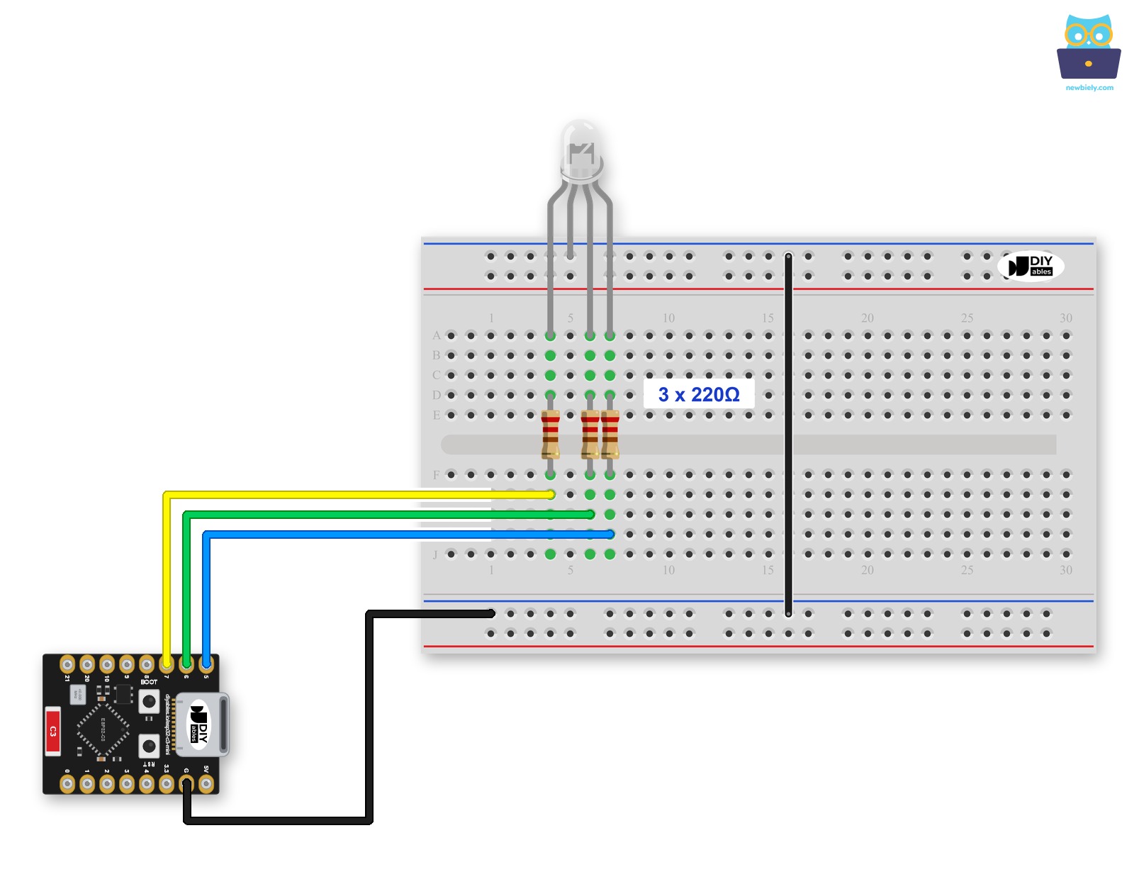
This image is created using Fritzing. Click to enlarge image
Here is the same wiring without a breadboard:
This image is created using Fritzing. Click to enlarge image
Wiring diagram between ESP32 C3 Super Mini and RGB LED module:
| RGB LED Module Pin | ESP32 C3 Super Mini Pin |
|---|---|
| R | GPIO7 |
| G | GPIO6 |
| B | GPIO5 |
| Common (Cathode-) | GND |
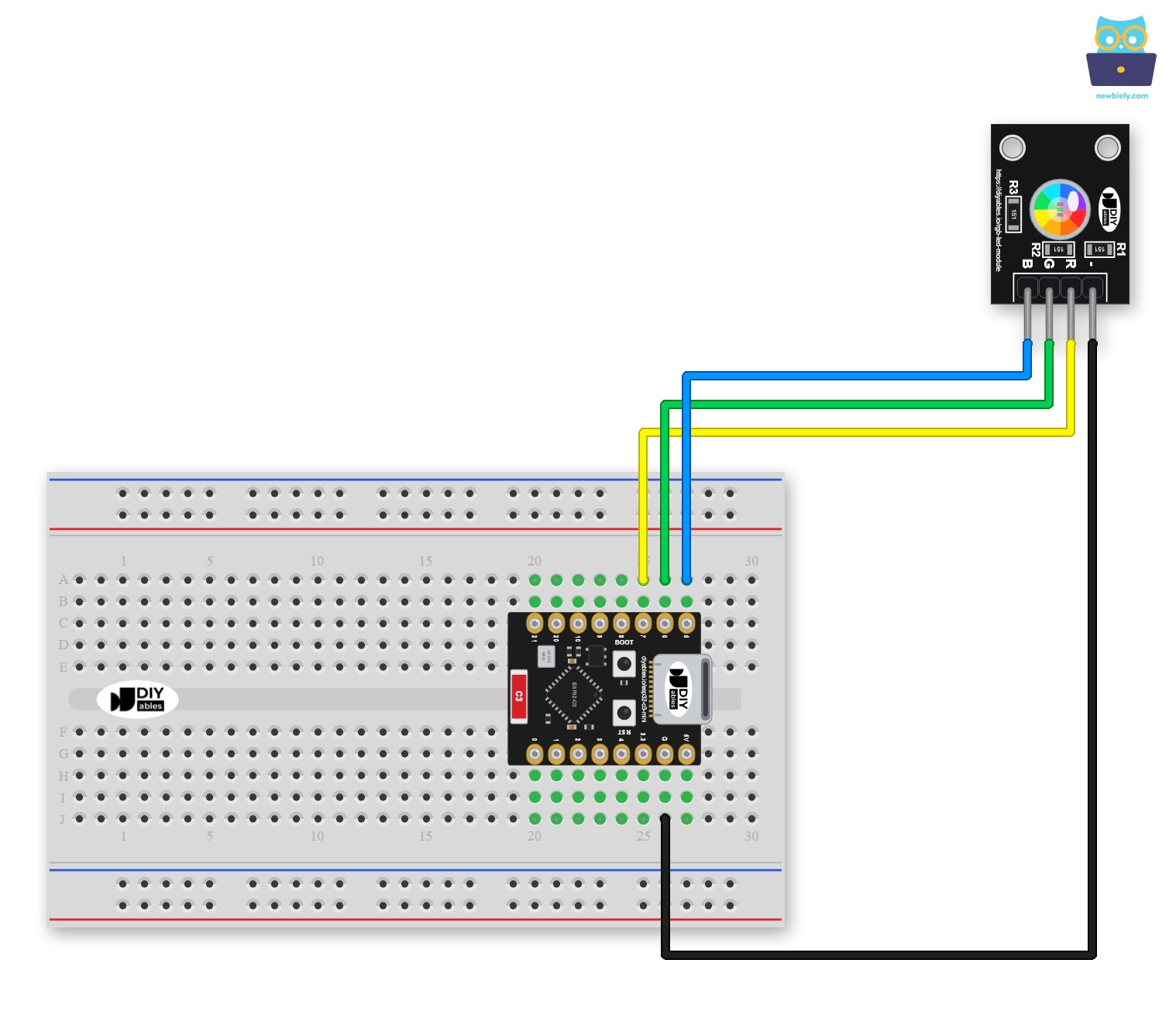
This image is created using Fritzing. Click to enlarge image
If you do not use a breadboard, wire it like this:
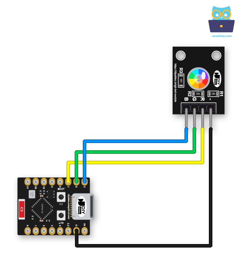
This image is created using Fritzing. Click to enlarge image
How To Control RGB LED
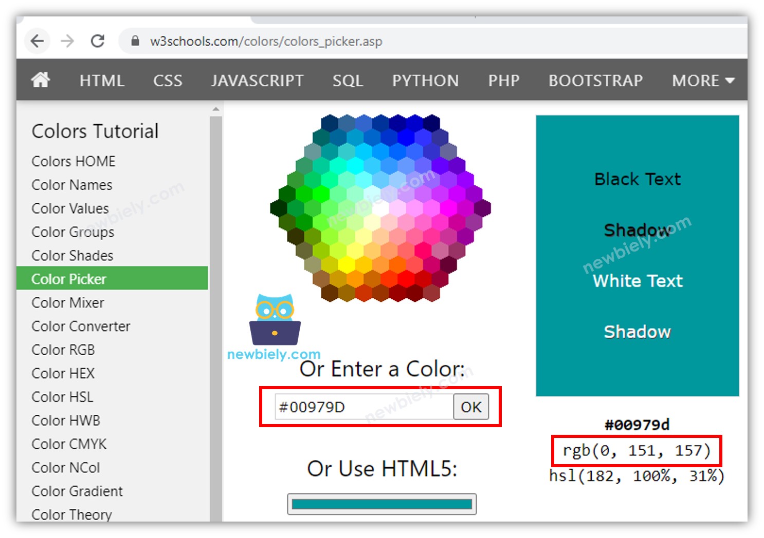
Let's say you want to show the color #00979D on the RGB LED. Follow these actions:
- Find the color code:
- Pick the color you want from the color picker
- To use a color from an image, try the online Colors From Image tool
- Convert it to R, G, B values: Use the tool from w3school and note the values. In this case: R = 0, G = 151, B = 157
- Define the pins: Name the ESP32 C3 Super Mini pins connected to R, G and B:
- Set the output mode: Configure these pins as outputs:
- Show the color: Send the values to the LED (#00979D → R = 0, G = 151, B = 157):
ESP32 C3 Super Mini - RGB LED Example Code
This code makes the RGB LED change color, one color each second.
What This Code Does:
- Sets the pins: GPIO7, GPIO6 and GPIO5 become PWM outputs for red, green and blue
- First color: #00C9CC (R = 0, G = 201, B = 204)
- Second color: #F7788A (R = 247, G = 120, B = 138)
- Third color: #34A853 (R = 52, G = 168, B = 83)
- Repeats: Each color stays on for 1 second, then the sequence starts again
Detailed Instructions
- New to ESP32 C3 Super Mini? Complete our Getting Started with ESP32 C3 Super Mini tutorial first to set up your development environment.
- Wire the parts: Follow the wiring diagram above, with R on GPIO7, G on GPIO6 and B on GPIO5
- Connect the board: Plug the ESP32 C3 Super Mini into your computer with a USB Type-C cable
- Open Arduino IDE: Start the Arduino IDE on your computer
- Select the board: Make sure ESP32 C3 Super Mini is selected in Tools > Board.
- Select the port: Choose the correct COM port in Tools > Port
- Copy the code: Paste the code above into a new sketch
- Upload the code: Click the Upload button
- Check the result: The LED changes between the three colors, one color each second
- Serial Monitor: This sketch prints nothing, so you do not need it. If you add Serial.begin(115200) later, set the Serial Monitor to 115200 baud
- Pro Tip: Colors mix best when you look through a thin piece of white paper placed over the LED.
Line-by-line Code Explanation
The above ESP32 C3 Super Mini code contains line-by-line explanation. Please read the comments in the code!
When using many colors, we could shorten the code by creating a function:
A small setColor() function keeps the code short when you use many colors.
What This Code Does:
- Same result: It shows the same three colors as the code above
- One line per color: Each color now needs only one setColor() call
- Easy to change: Add a new color by adding one more line
Applications and Project Ideas
An ESP32 C3 Super Mini RGB LED project can show information with color.
- Status Light: Show green for OK and red for an error
- Mood Lamp: Change the room light color slowly
- Temperature Display: Show blue for cold and red for hot
- WiFi Indicator: Use one color for connected and another for not connected
- Notification Light: Flash a color when a new message arrives
Challenge Yourself
Try these challenges to grow your RGB LED skills.
- Easy: Change the three colors to your favorite colors
- Easy: Add a fourth color to the sequence with one more setColor() line
- Medium: Make the delay shorter or longer for each color
- Medium: Add a button that moves to the next color when pressed
- Advanced: Fade smoothly from one color to the next with millis() instead of delay()
- Advanced: Host a small web page on the ESP32 C3 Super Mini that sets the LED color over WiFi