
ESP32 C3 Super Mini - Touch Sensor - LED
This tutorial shows you how to use the ESP32 C3 Super Mini to control an LED with a touch sensor. The LED stays on while your finger is on the pad, and it turns off when you let go. It is a simple first project for beginners.
In this tutorial, you'll learn:
- How to wire a touch sensor and an LED to the ESP32 C3 Super Mini
- How to read the touch sensor state in code
- How to turn the LED on while the touch sensor is being touched
- How to turn the LED off when the touch sensor is NOT being touched
- How to watch the touch state on the Serial Monitor
WARNING
The ESP32 C3 chip does NOT have built-in capacitive touch pins, so touchRead() does NOT work on the ESP32 C3 Super Mini. This tutorial uses an external touch sensor module and reads it with digitalRead().
Hardware Preparation
Or you can buy the following kits:
| 1 | × | DIYables Sensor Kit (18 sensors/displays) |
Additionally, some of these links are for products from our own brand, DIYables .
Buy Note: Use the LED Module for easier wiring. It includes an integrated resistor.
Overview of LED and Touch Sensor
A touch sensor is a small module that gives a digital signal when your finger touches its pad, and an LED is a small light you can turn on and off.
Key Features:
- Touch Sensor: It has no moving part and reads like a button with digitalRead().
- LED: It turns on and off with a digital signal from the board.
- Together: The sensor reports the touch, and the board turns that report into light.
Technical Specifications:
- Touch sensor power: 3.3V from the ESP32 C3 Super Mini
- Touch sensor output: digital, HIGH when touched and LOW when not touched
- LED resistor: 220 ohm
Each part has its own tutorial with the pinout, how it works, wiring and code:
Pinout
Here are the pins you will connect in this project.
- Touch Sensor VCC: connect to 3.3V
- Touch Sensor GND: connect to GND (0V)
- Touch Sensor SIGNAL: sends the HIGH or LOW signal to the digital input pin (the code comment calls it the OUTPUT pin)
- LED Anode (+): the longer leg, controlled by the output pin through the resistor
- LED Cathode (-): the shorter leg, connects to GND
Wiring Diagram
The touch sensor uses three wires, and the LED uses two wires plus a resistor.
- Note: Power the touch sensor from the 3.3V pin, never from 5V. A 5V supply makes the SIGNAL pin output 5V, which can damage a GPIO pin.
- Note: Always use the 220 ohm resistor with the LED, or the LED can burn out.
- Note: Keep the sensor wires short. Long wires near the pad can make the sensor trigger by itself.
| Component Pin | ESP32 C3 Super Mini Pin |
|---|---|
| Touch Sensor VCC | 3.3V |
| Touch Sensor GND | GND |
| Touch Sensor SIGNAL | GPIO7 |
| LED Anode (+) | GPIO3 (through 220 ohm resistor) |
| LED Cathode (-) | GND |
The wiring diagram with power supply from USB cable:
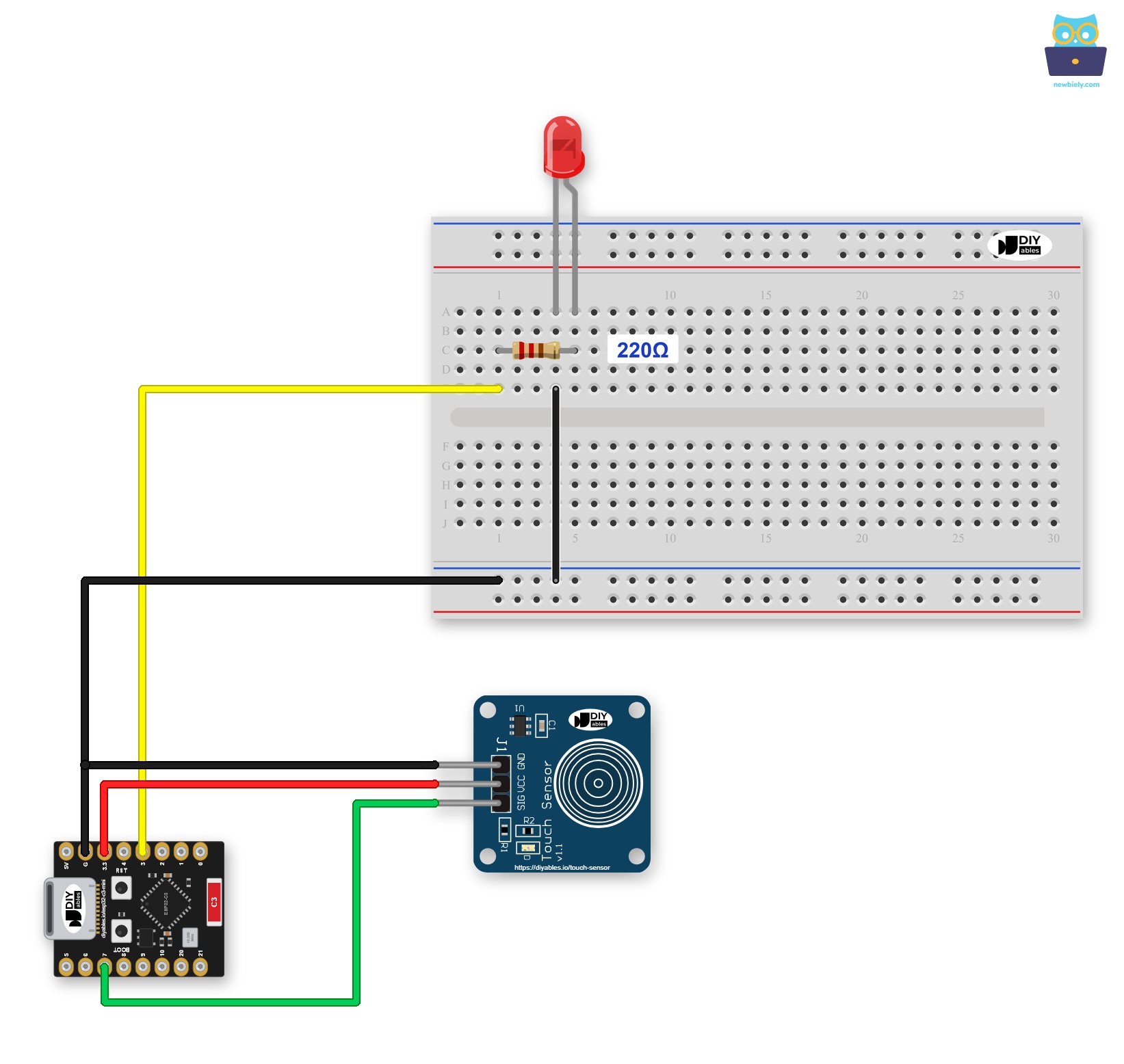
This image is created using Fritzing. Click to enlarge image
The wiring diagram with power supply from 5V adapter:
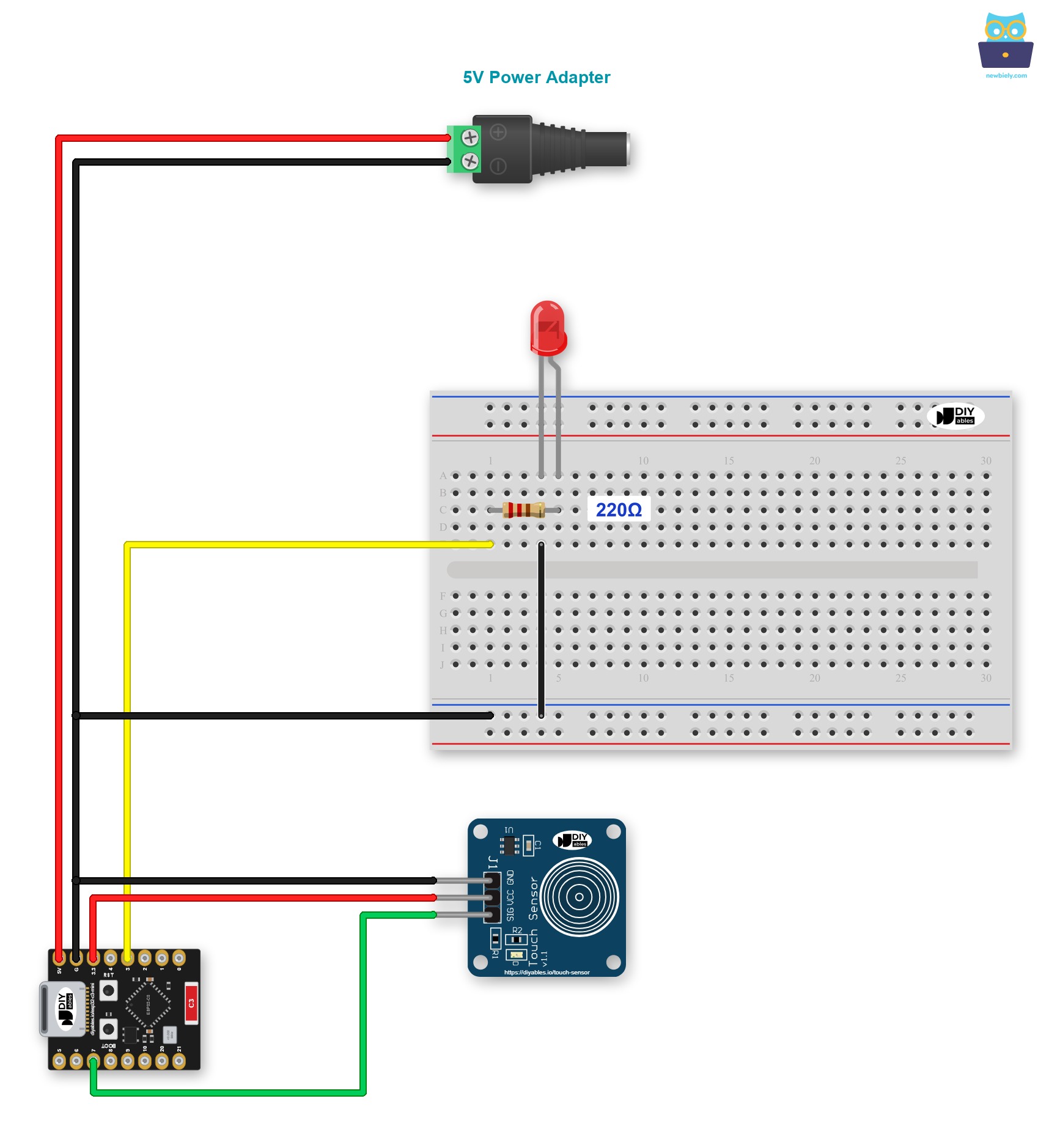
This image is created using Fritzing. Click to enlarge image
ESP32 C3 Super Mini Code
The code below lets the touch sensor on GPIO7 control the LED on GPIO3.
What This Code Does:
- Starts Serial: opens the Serial Monitor at 115200 baud.
- Sets the pins: GPIO7 is an input for the sensor, and GPIO3 is an output for the LED.
- Reads the sensor: digitalRead() checks the sensor state again and again.
- Touched: when the state is HIGH, the LED turns on.
- Not touched: when the state is LOW, the LED turns off.
Detailed Instructions
- New to ESP32 C3 Super Mini? Complete our Getting Started with ESP32 C3 Super Mini tutorial first to set up your development environment.
- Wire it up: Connect the touch sensor and the LED as shown above.
- Connect the board: Plug the ESP32 C3 Super Mini into your computer with a USB Type-C cable.
- Open the IDE: Open Arduino IDE on your computer.
- Select the board: Make sure ESP32 C3 Super Mini is selected in Tools > Board.
- Select the port: Pick the COM port of your board in Tools > Port.
- Copy the code: Copy the code above and paste it into Arduino IDE.
- Upload: Click the Upload button on Arduino IDE.
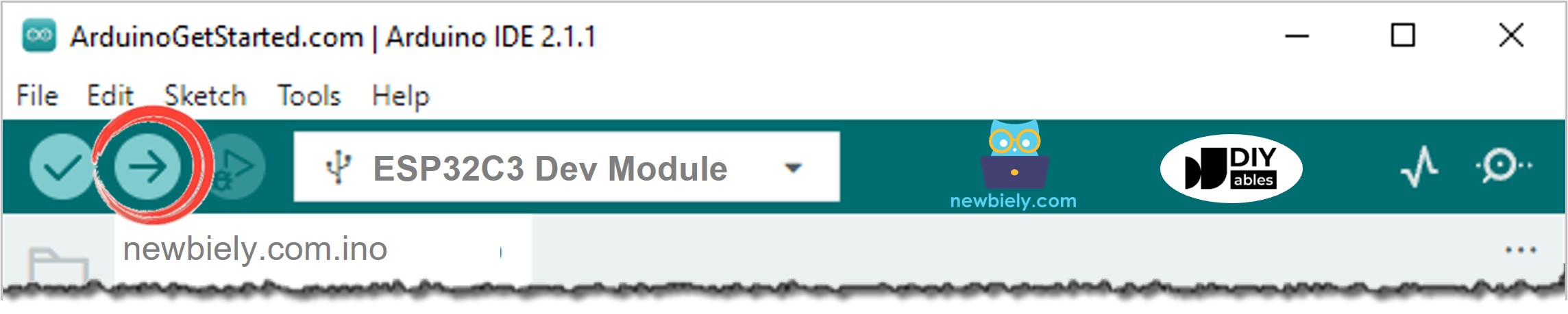
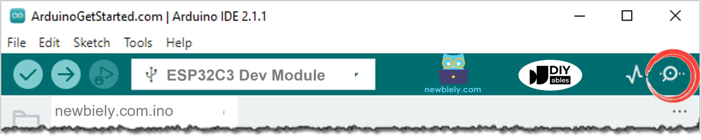
- Open Serial Monitor: Open it on Arduino IDE and set the baud rate to 115200.
- Test it: Touch and keep touching the touch sensor for several seconds.
- Watch the LED: See the LED turn on, then turn off when you let go.
- Check the result: See the touch state on the Serial Monitor. It looks like the below:
- Pro Tip: If the LED stays on by itself, move your hand and the wires away from the pad and reset the board, so the sensor can calibrate again.
Line-by-line Code Explanation
The above ESP32 C3 Super Mini code contains line-by-line explanation. Please read the comments in the code!
Project Ideas
This touch sensor LED idea can control many real things.
- Touch Lamp: Keep a small light on while your hand rests on the pad.
- Hidden Switch: Put the sensor behind a thin panel and light a sign when touched.
- Touch Indicator: Show with an LED that a touch panel is working.
- Night Light: Touch the pad to see your way in a dark room.
- Game Input: Use the pad as a game button with an LED as feedback.
Challenge Yourself
Try these small upgrades to learn more about the ESP32 C3 Super Mini and the touch sensor.
- Easy: Reverse the logic, so the LED is on when the sensor is NOT touched.
- Easy: Print the text only when the state changes, not in every loop.
- Medium: Toggle the LED between ON and OFF each time the sensor is touched.
- Medium: Count the touches and print the total on the Serial Monitor.
- Advanced: Add a second LED on GPIO5 that turns on only after a long touch.
- Advanced: Add a second touch sensor on GPIO6, so one pad turns the LED on and the other turns it off.