
ESP32 C3 Super Mini - DIP Switch
A DIP (Dual In-line Package) switch is a small block of slide switches that you set by hand. It is used for device addresses, communication settings, security codes and operating modes. This tutorial shows you how to use a DIP switch with the ESP32 C3 Super Mini.
In this tutorial, you will learn:
- What a DIP switch is and how each position works
- How to wire a DIP switch to the ESP32 C3 Super Mini
- How to read the ON/OFF state of each position in code
- How to turn the positions into one number (binary encoding)
- Project ideas that use a DIP switch
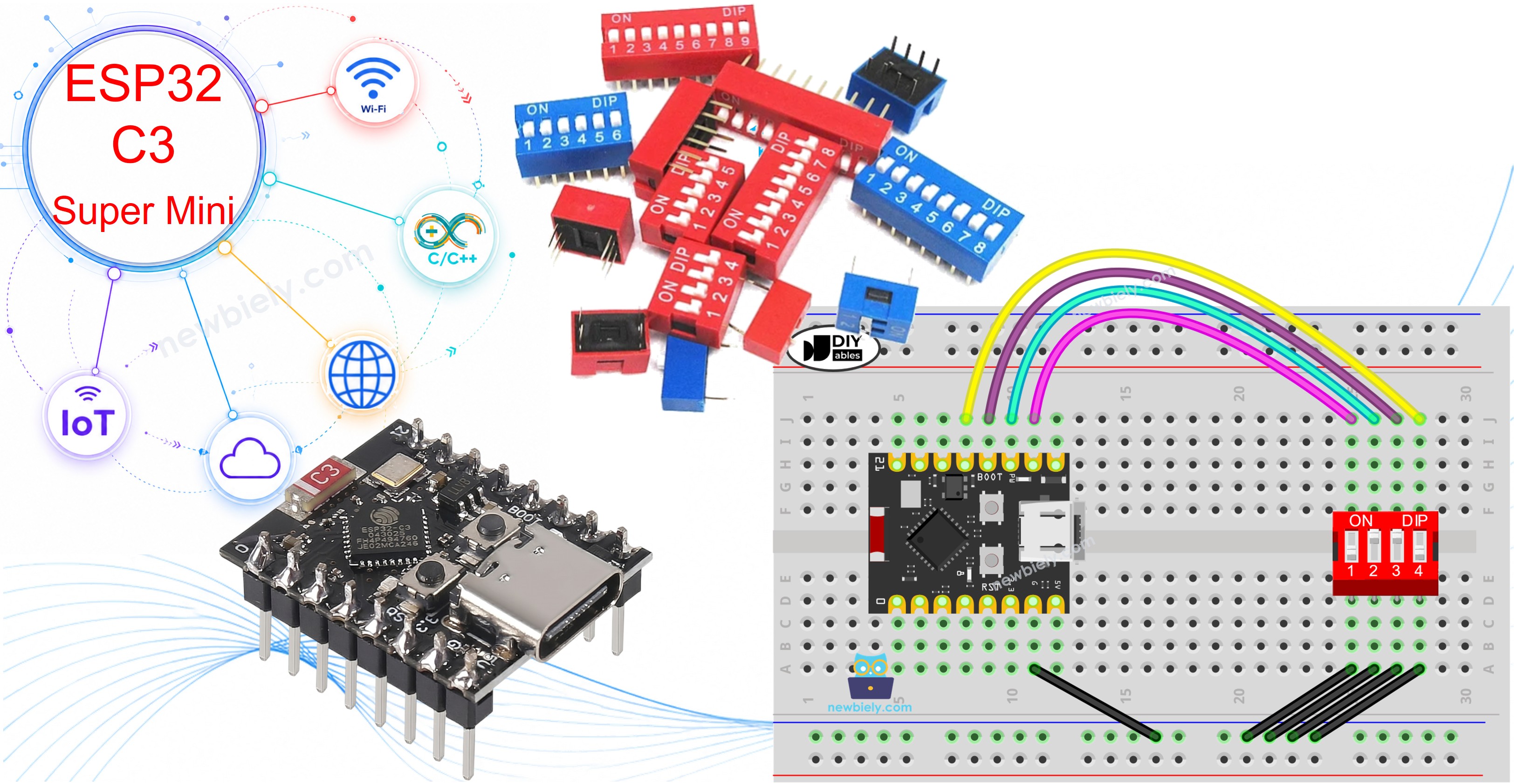
Hardware Preparation
| 1 | × | ESP32 C3 Super Mini | |
| 1 | × | USB Cable Type-A to Type-C (for USB-A PC) | |
| 1 | × | USB Cable Type-C to Type-C (for USB-C PC) | |
| 1 | × | DIP Switch | |
| 1 | × | Breadboard | |
| 1 | × | Jumper Wires |
Or you can buy the following kits:
| 1 | × | DIYables Sensor Kit (18 sensors/displays) |
Additionally, some of these links are for products from our own brand, DIYables .
Overview of DIP Switch
A DIP switch is a group of tiny slide switches in one package, and each small switch is called a "position".
Key Features:
- Many switches in one part: Each position is its own ON/OFF switch
- Set by hand: You slide a position with a pen tip or a small screwdriver
- Keeps its setting: The value stays after power off
- No polarity: The two pins of a position can be swapped
- Beginner friendly: Works with the 3.3V logic of the ESP32 C3 Super Mini
Technical Specifications:
- Common sizes: 2, 4, 5, 6, 8 and 10 positions
- Pin count: 2 pins per position, half on each row
- Switch type: Mechanical SPST per position
- Contact resistance: Near 0 ohm when ON, very high when OFF
- Logic level used here: 3.3V from the ESP32 C3 Super Mini
Each position stands for one bit of a number. By sliding the positions between ON and OFF, you set the number you want.
Pinout
A DIP switch has two rows of pins, and each row has the same number of pins as positions.
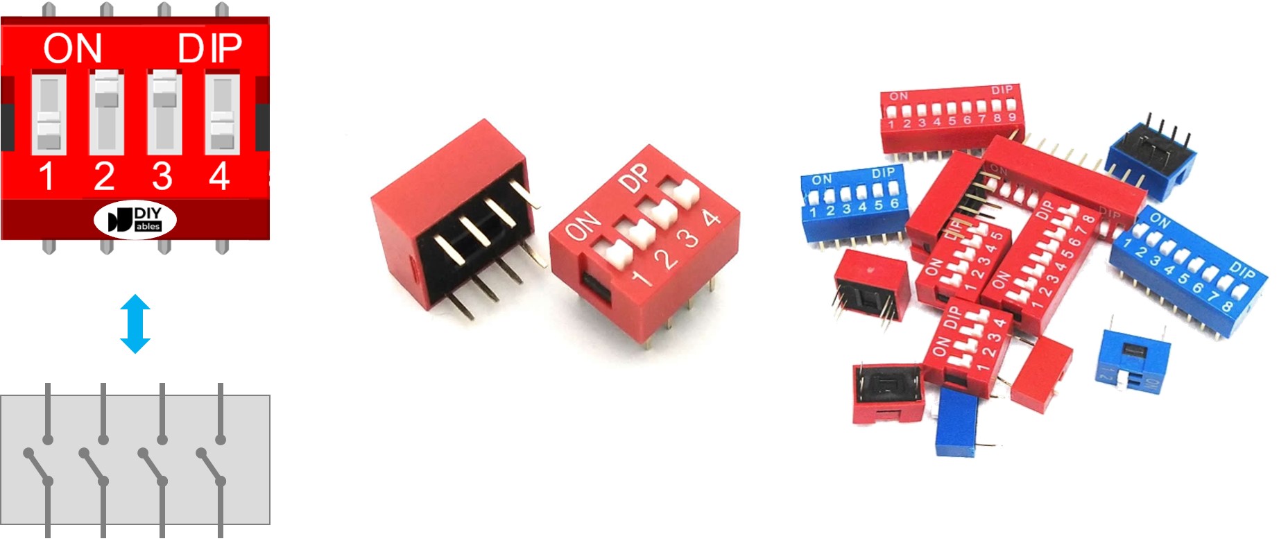
- Top row pins: One side of each slide switch
- Bottom row pins: The other side of the same slide switch
- Pin pairs: Two pins facing each other make one position
- No fixed order: The two sides can be used interchangeably
- Example: A 4-position DIP switch has 8 pins in total, 4 on each side
How It Works
Each position of a DIP switch works like a wire that you can open or close.
- ON position: The switch is closed, so current can pass through
- OFF position: The switch is open, so current is blocked
Wire one side of a position to GND and the other side to an ESP32 C3 Super Mini pin set as a pull-up input. The table below shows what you read:
| DIP switch position | Binary representation | Circuit state | ESP32 C3 Super Mini pin state |
|---|---|---|---|
| ON | 1 | CLOSED | LOW |
| OFF | 0 | OPEN | HIGH |
※ NOTE THAT:
The ESP32 C3 Super Mini uses 3.3V logic only. Never connect a 5V signal to any GPIO pin.
The next parts use a 4-position DIP switch as an example. You can adapt the same idea for 2-position, 3-position, 5-position, 6-position, 8-position and 10-position DIP switches.
Wiring Diagram
Connect one side of each position to a GPIO pin, and the other side of every position to GND.
- Note: Use 3.3V logic only. Do not feed 5V into a GPIO pin.
- Note: GPIO8 and GPIO9 are boot strapping pins. Slide positions 3 and 4 to OFF before you power up or reset the board, or it will not start normally.
- Note: Do not use GPIO20 or GPIO21 — the Serial Monitor uses them.
- Note: The two pins of one position can be swapped.
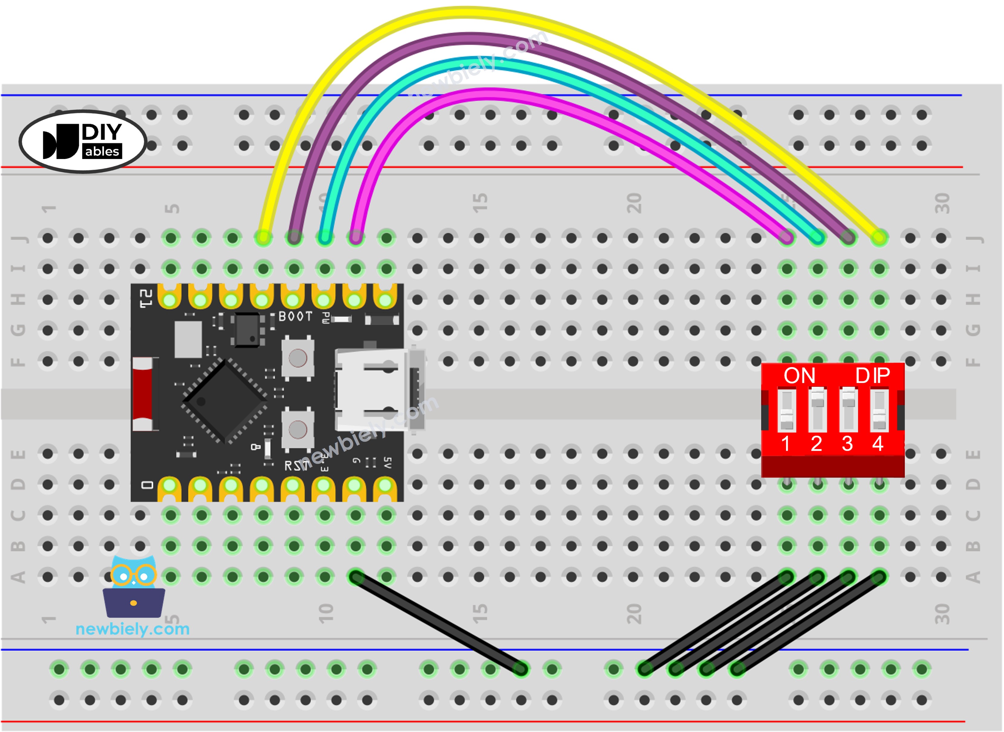
This image is created using Fritzing. Click to enlarge image
| DIP Switch Pin | ESP32 C3 Super Mini Pin |
|---|---|
| Position 1 (side A) | GPIO6 |
| Position 2 (side A) | GPIO7 |
| Position 3 (side A) | GPIO8 |
| Position 4 (side A) | GPIO9 |
| Position 1 to 4 (side B) | GND |
ESP32 C3 Super Mini Code - DIP Switch
We will learn through two pieces of code:
- Reading the ON/OFF state of each position on the DIP switch.
- Encoding the positions into a number.
ESP32 C3 Super Mini code - Reading the ON/OFF state of the DIP switch
This first sketch prints the state of every position, one line per position.
What This Code Does:
- Sets GPIO6, GPIO7, GPIO8 and GPIO9 as inputs with the internal pull-up on
- Reads each DIP switch position every half second
- Prints ON when the pin reads LOW, which means the switch is closed
- Prints OFF when the pin reads HIGH, which means the switch is open
- Adds a small delay so the Serial Monitor stays easy to read
Detailed Instructions
- New to ESP32 C3 Super Mini? Complete our Getting Started with ESP32 C3 Super Mini tutorial first to set up your development environment.
- Wire the parts: Follow the wiring diagram above to connect the DIP switch to the ESP32 C3 Super Mini.
- Connect the board: Plug the ESP32 C3 Super Mini into your PC with a USB Type-C cable.
- Open Arduino IDE: Launch the Arduino IDE software.
- Select the board: Make sure ESP32 C3 Super Mini is selected in Tools > Board.
- Select the port: Pick the COM port of your ESP32 C3 Super Mini in Tools > Port.
- Upload the code: Copy the code above, paste it into the Arduino IDE, then click the Upload button.
- Open Serial Monitor: Set the baud rate to 115200.
- Slide the positions: Move each position of the DIP switch to ON one by one.
- See the result: Watch the Serial Monitor print the new states.
- Pro Tip: If a position always reads ON, check that its GND wire does not touch the GPIO wire.
ESP32 C3 Super Mini code - Encoding the states of DIP switch into a number
This second sketch turns the four positions into one decimal number.
What This Code Does:
- Reads the same four pins: GPIO6, GPIO7, GPIO8 and GPIO9
- Uses position 1 as the highest bit and position 4 as the lowest bit
- Sets a bit to 1 when its position is ON
- Prints the final number, from 0 to 15 for a 4-position DIP switch
- Repeats the reading every half second
Detailed Instructions
- New to ESP32 C3 Super Mini? Complete our Getting Started with ESP32 C3 Super Mini tutorial first to set up your development environment.
- Keep the same wiring: The wiring diagram above does not change.
- Connect the board: Plug the ESP32 C3 Super Mini into your PC with a USB Type-C cable.
- Open Arduino IDE: Launch the Arduino IDE software.
- Select the board: Make sure ESP32 C3 Super Mini is selected in Tools > Board.
- Select the port: Pick the COM port of your ESP32 C3 Super Mini in Tools > Port.
- Upload the code: Copy the second code above, paste it into the Arduino IDE, then click the Upload button.
- Open Serial Monitor: Set the baud rate to 115200.
- Slide the positions: Move each position of the DIP switch to ON one by one.
- See the result: The printed number changes as you slide the positions.
- Pro Tip: An 8-position DIP switch gives you 0 to 255. Just change POSITION_NUM and add more pins.
The value depends on the position of each slide switch. The table below shows the mapping between the ON/OFF positions and the integer value for a 4-position DIP switch:
| Position-1 | Position-2 | Position-3 | Position-4 | Binary Value | Decimal Value |
|---|---|---|---|---|---|
| OFF | OFF | OFF | OFF | 0000 | 0 |
| OFF | OFF | OFF | ON | 0001 | 1 |
| OFF | OFF | ON | OFF | 0010 | 2 |
| OFF | OFF | ON | ON | 0011 | 3 |
| OFF | ON | OFF | OFF | 0100 | 4 |
| OFF | ON | OFF | ON | 0101 | 5 |
| OFF | ON | ON | OFF | 0110 | 6 |
| OFF | ON | ON | ON | 0111 | 7 |
| ON | OFF | OFF | OFF | 1000 | 8 |
| ON | OFF | OFF | ON | 1001 | 9 |
| ON | OFF | ON | OFF | 1010 | 10 |
| ON | OFF | ON | ON | 1011 | 11 |
| ON | ON | OFF | OFF | 1100 | 12 |
| ON | ON | OFF | ON | 1101 | 13 |
| ON | ON | ON | OFF | 1110 | 14 |
| ON | ON | ON | ON | 1111 | 15 |
Line-by-line Code Explanation
The ESP32 C3 Super Mini code above contains line-by-line explanation. Please read the comments in the code!
Application/Project Ideas
Here are simple ways to use a DIP switch with the ESP32 C3 Super Mini.
- Device Address: Give each board a number so many boards can share one bus.
- Mode Selector: Pick one of 16 program modes without changing the code.
- Secret Code Lock: Open a relay only when the right pattern is set.
- Sensor Calibration: Choose a threshold step for a sensor reading.
- Wi-Fi Profile Picker: Select which saved Wi-Fi network the board joins.
- LED Pattern Chooser: Change a light animation by sliding one position.
Challenge Yourself
Try these steps to go further with the ESP32 C3 Super Mini and a DIP switch.
- Easy: Turn an external LED on GPIO3 ON when position 1 is ON.
- Easy: Print the value in binary with Serial.println(encoded_state, BIN).
- Medium: Print a message only when the encoded number changes.
- Medium: Use the number to set a blink speed, from fast to slow.
- Advanced: Add a 5th and 6th position on GPIO2 and GPIO4 for values 0 to 63.
- Advanced: Send the DIP switch value over Wi-Fi to a web page.