
ESP32 C3 Super Mini - DRV8833 DC Motor Driver
The ESP32 C3 Super Mini is small, and so is the DRV8833 motor driver. Put them together and you get a motor controller that fits inside a matchbox-sized robot. This tutorial starts with one DC motor, then moves on to two motors, like the wheels of a small car.
In this tutorial, you'll learn:
- What the DRV8833 does and why it suits a 3.3V board
- How the four IN pins set direction, speed, coast and brake
- How to wire one DC motor to the ESP32 C3 Super Mini through the DRV8833
- How to change the speed with PWM, using analogWrite()
- How to wire and drive two DC motors for a simple robot car
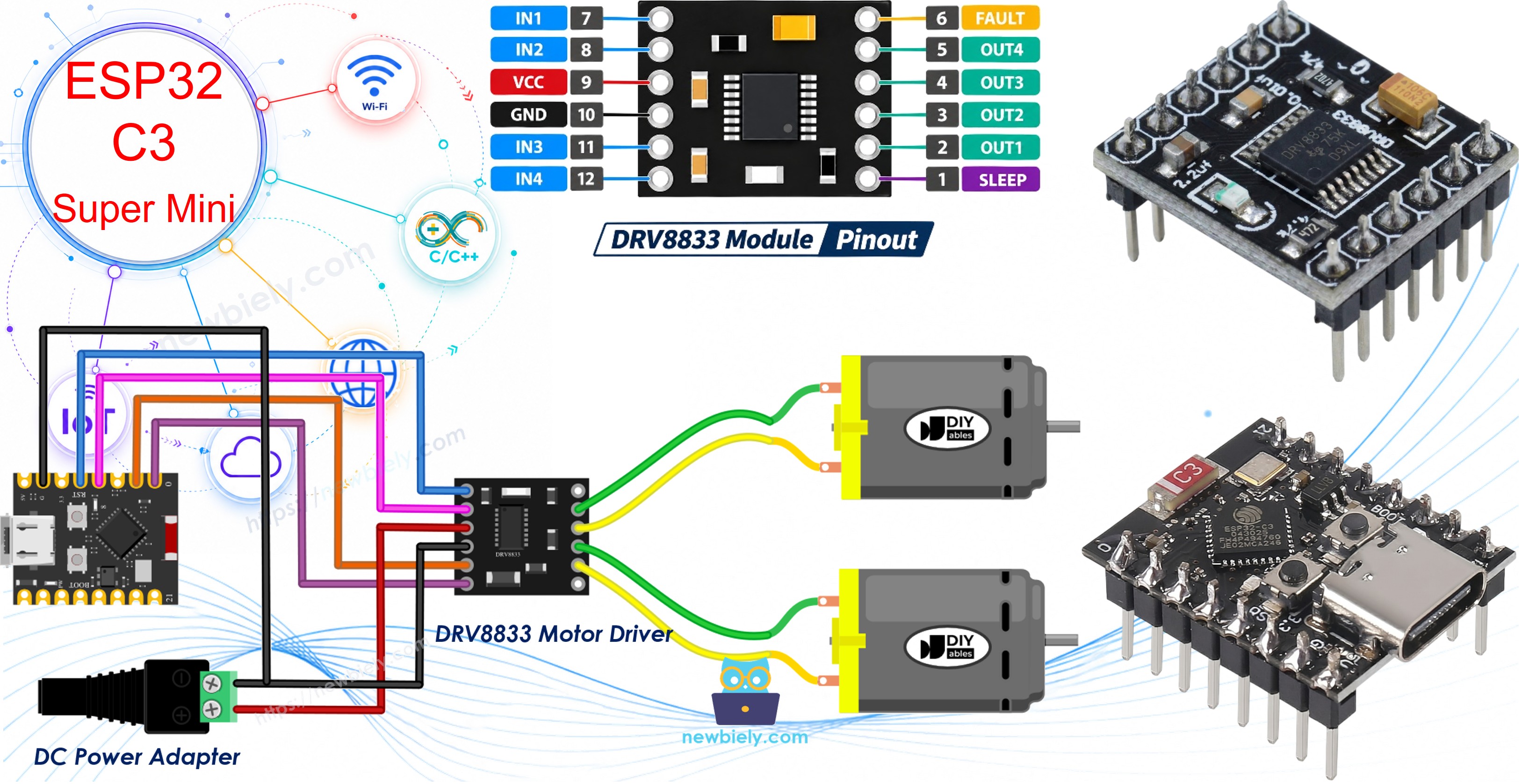
Hardware Preparation
Or you can buy the following kits:
| 1 | × | DIYables Sensor Kit (18 sensors/displays) |
Additionally, some of these links are for products from our own brand, DIYables .
Part 1 needs only one DC motor. The second motor is for Part 2.
Overview of DRV8833 DC Motor Driver
A GPIO pin of the ESP32 C3 Super Mini gives only a few milliamps at 3.3V. A DC motor needs hundreds of milliamps. The DRV8833 sits in the middle: the board sends small control signals, and the driver switches the motor current from a separate power supply. Inside the chip there are two H-bridges, so one module can run two DC motors, and each motor can turn both ways.
Key Features:
- Two motor channels: motor A on OUT1/OUT2, motor B on OUT3/OUT4
- Motor supply (VCC pin): 2.7V to 10.8V
- About 1.5A per channel continuous, 2A peak with good cooling
- MOSFET outputs with low resistance (about 360 mΩ), so less heat and less voltage loss than the L298N
- PWM speed control up to 50 kHz
- Built-in protection: under-voltage lockout, over-current and thermal shutdown
Why DRV8833 is Great for the ESP32 C3 Super Mini:
- No logic power pin. The chip makes its own logic voltage, so 3.3V control signals work directly
- Small enough to sit next to the Super Mini on a mini breadboard
- Runs well from 4 x AA batteries (about 6V) or a 5V adapter
- It can also drive one small bipolar stepper motor, but this tutorial uses DC motors only
DRV8833 Module Pinout
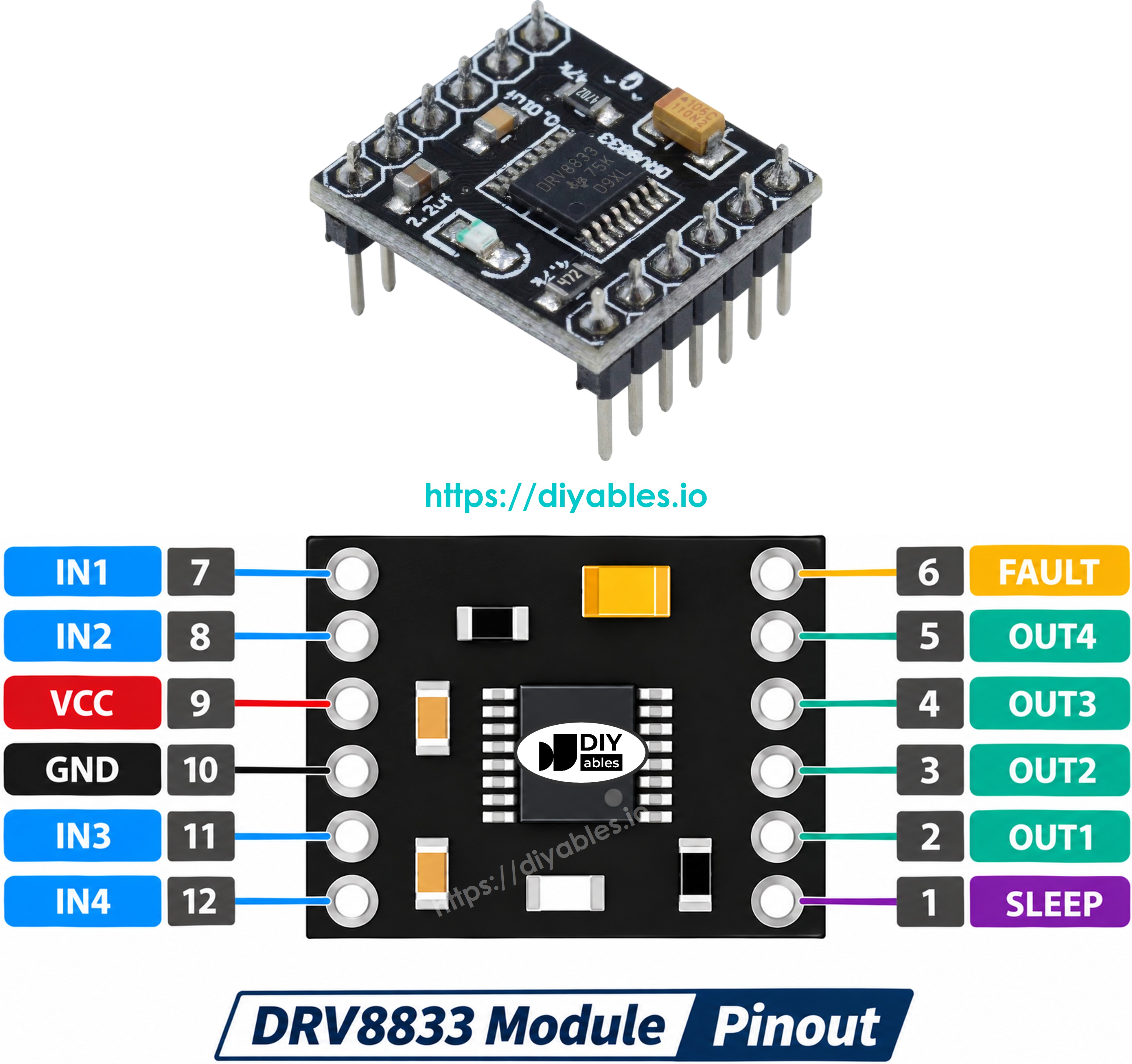
The common red or blue DRV8833 board has these pins:
- IN1, IN2: control inputs for motor A. Connect them to two PWM pins of the ESP32 C3 Super Mini.
- IN3, IN4: control inputs for motor B. Also two PWM pins.
- OUT1, OUT2: outputs to the two wires of motor A.
- OUT3, OUT4: outputs to the two wires of motor B.
- VCC: motor power, 2.7V to 10.8V, from the external supply (not from the board).
- GND: ground. It must be shared by the supply, the driver and the ESP32 C3 Super Mini.
- EEP: the sleep pin (nSLEEP). HIGH = driver on, LOW = driver asleep. In this tutorial it goes to 3.3V.
- ULT: the fault output (nFAULT). It goes LOW on over-current or overheating. You can leave it unconnected.
※ NOTE THAT:
Pin labels vary between makers. Some modules print AIN1, AIN2, BIN1, BIN2, AOUT1, AOUT2, BOUT1, BOUT2, SLP and FLT instead. The job of each pin is the same.
How the IN Pins Control a Motor
The DRV8833 has no ENA or ENB speed pin like the L298N. Each motor uses only its two IN pins. Their logic levels set what the motor does:
| IN1 (or IN3) | IN2 (or IN4) | Motor action |
|---|---|---|
| LOW | LOW | Coast - power off, the motor rolls to a stop |
| PWM / HIGH | LOW | Forward - the PWM duty sets the speed |
| LOW | PWM / HIGH | Reverse - the PWM duty sets the speed |
| HIGH | HIGH | Brake - the motor stops fast |
So for speed control, PWM goes on one IN pin while the other stays LOW. This means both IN pins of a motor must be PWM-capable. On the ESP32 C3 Super Mini almost every GPIO can make PWM, so this is easy.
Part 1: Control One DC Motor
Wiring Diagram - One Motor
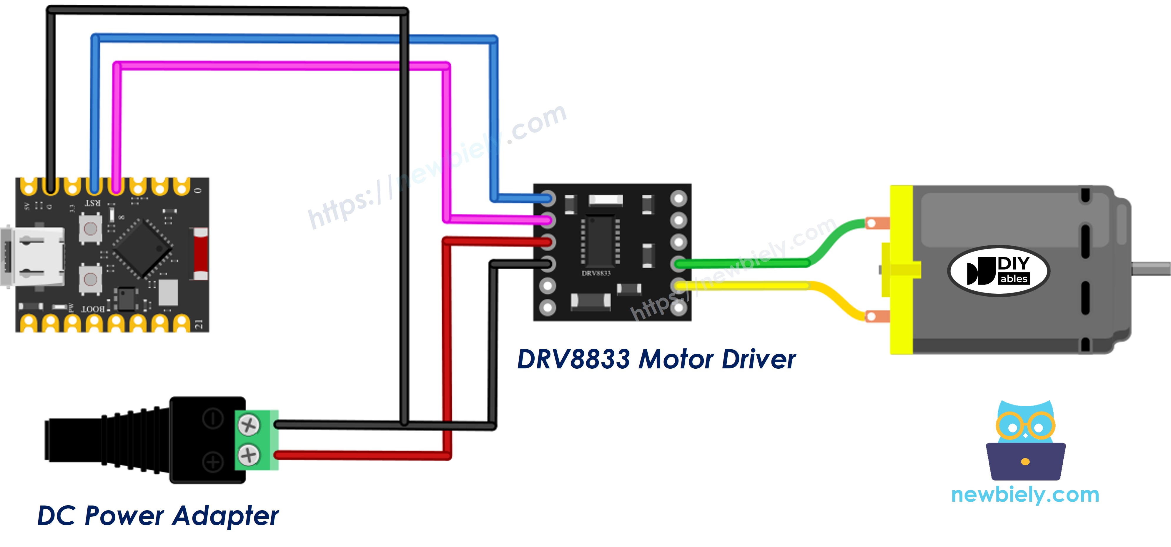
This image is created using Fritzing. Click to enlarge image
| DRV8833 Pin | Connect To |
|---|---|
| IN1 | ESP32 C3 Super Mini GPIO4 |
| IN2 | ESP32 C3 Super Mini GPIO3 |
| EEP | ESP32 C3 Super Mini 3.3V |
| GND | ESP32 C3 Super Mini GND and power supply (-) |
| VCC | 5V power supply (+) |
| OUT1 | Motor wire 1 |
| OUT2 | Motor wire 2 |
- Note: Power the motor from the 5V adapter through the DC power jack. Never take motor power from the 5V or 3.3V pin of the ESP32 C3 Super Mini.
- Note: Connect all grounds together: adapter (-), DRV8833 GND and ESP32 C3 Super Mini GND. Without a common ground, the motor does not respond.
- Note: GPIO4 and GPIO3 are free, PWM-capable pins. Avoid GPIO2, GPIO8 and GPIO9 (boot pins), GPIO18/GPIO19 (USB) and GPIO20/GPIO21 (serial).
- Note: If the motor turns the wrong way, swap the two motor wires on OUT1 and OUT2.
ESP32 C3 Super Mini Code - One Motor
This sketch runs one motor through every state of the truth table above.
What the code does:
- Sets GPIO4 and GPIO3 as the IN1 and IN2 outputs
- Ramps the motor up from stop to full speed in the forward direction
- Holds full speed for 2 seconds
- Lets the motor coast to a stop
- Runs the motor in reverse at about 70% speed
- Brakes the motor and repeats
- Prints each state to the Serial Monitor
Detailed Instructions
- New to ESP32 C3 Super Mini? Complete our Getting Started with ESP32 C3 Super Mini tutorial first to set up your development environment.
- Wire the parts: Follow the one-motor wiring diagram. Leave the 5V adapter unplugged for now.
- Connect USB cable: Plug the ESP32 C3 Super Mini into your computer with a USB Type-C cable.
- Open Arduino IDE: Select the ESP32 C3 Super Mini board and its COM port.
- Copy the code: Paste the code above into a new sketch. No extra library is needed, analogWrite() is built in.
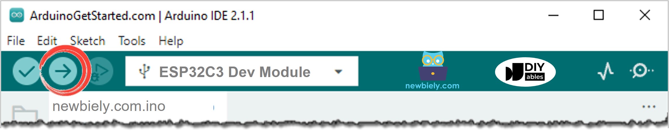
- Upload the code: Click the Upload button.
- Power the motor: Now plug in the 5V adapter.
- Open Serial Monitor: Set the baud rate to 115200.
- Watch the motor: It speeds up, runs, coasts, turns backward, then brakes.
- Pro Tip: Listen to the stop. A coast stop is slow and soft. A brake stop is short and sharp. That is the difference between LOW/LOW and HIGH/HIGH.
Line-by-line Code Explanation
The above ESP32 C3 Super Mini code contains line-by-line explanation. Please read the comments in the code!
Part 2: Control Two DC Motors
With the second channel, the same module can drive the left and right wheels of a small robot car. Motor A is the left wheel and motor B is the right wheel.
Wiring Diagram - Two Motors
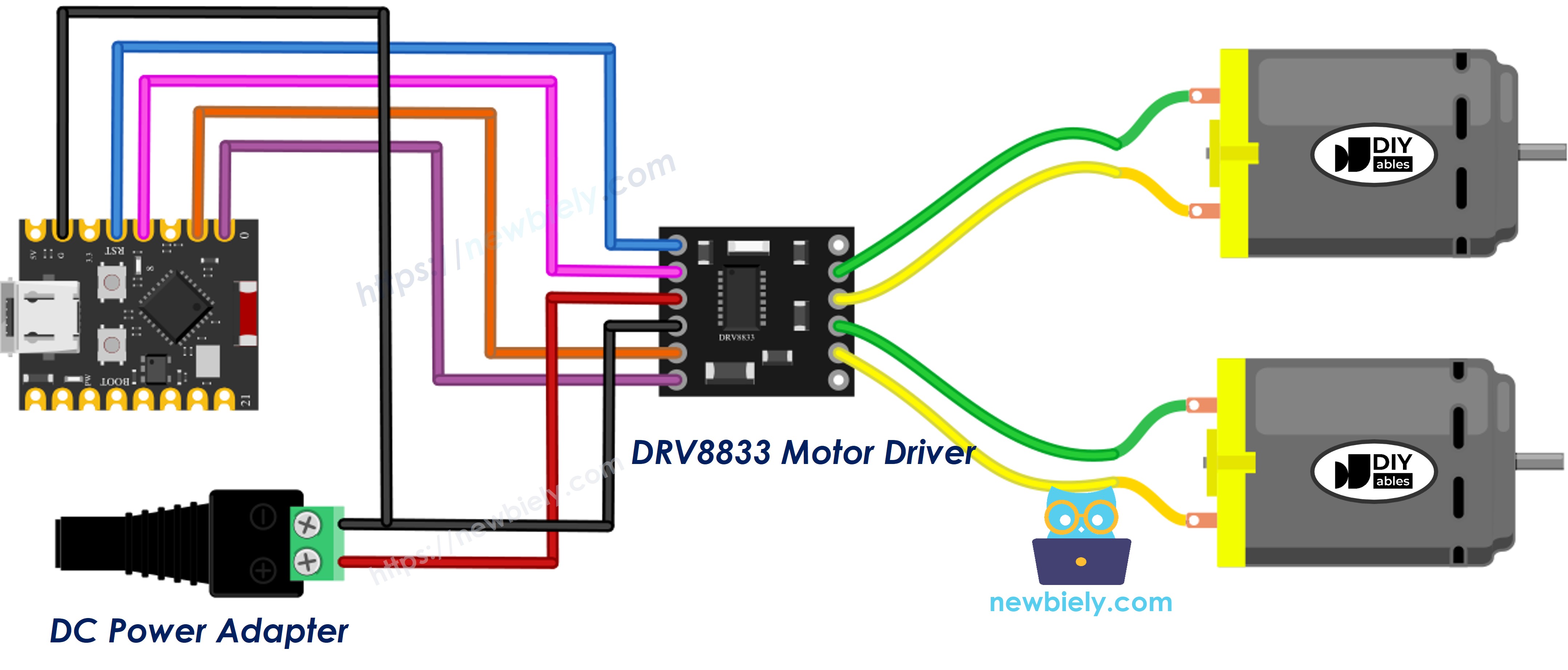
This image is created using Fritzing. Click to enlarge image
| DRV8833 Pin | Connect To |
|---|---|
| IN1 | ESP32 C3 Super Mini GPIO4 |
| IN2 | ESP32 C3 Super Mini GPIO3 |
| IN3 | ESP32 C3 Super Mini GPIO1 |
| IN4 | ESP32 C3 Super Mini GPIO0 |
| EEP | ESP32 C3 Super Mini 3.3V |
| GND | ESP32 C3 Super Mini GND and power supply (-) |
| VCC | 5V power supply (+) |
| OUT1, OUT2 | Motor A (left wheel) |
| OUT3, OUT4 | Motor B (right wheel) |
- Note: Two motors pull about twice the current. A 5V 2A adapter or a 4 x AA battery pack is a good choice.
- Note: For a battery robot, keep the battery voltage below 10.8V. A 2S Li-ion pack (up to 8.4V) is fine, a 3S pack is too high.
- Note: GPIO1 and GPIO0 are also free, PWM-capable pins, so the four IN pins stay away from the boot pins (GPIO2, GPIO8, GPIO9) and the USB pins (GPIO18, GPIO19).
ESP32 C3 Super Mini Code - Two Motors
This sketch uses a helper function for each motor. You give it a signed speed: a positive number turns the wheel forward, a negative number turns it backward, and 0 stops it.
What the code does:
- Sets GPIO4, GPIO3, GPIO1 and GPIO0 as the IN1 to IN4 outputs
- Creates motorA(speed) and motorB(speed) with a speed from -255 to 255
- Drives the car forward, stops, then drives backward
- Turns left by running the left wheel back and the right wheel forward
- Turns right by doing the opposite
- Prints every action and both speed values to the Serial Monitor
Detailed Instructions
- Wire the second motor: Add motor B and the IN3/IN4 wires as in the two-motor diagram.
- Lift the wheels: If the motors are already on a car, put it on a box so it cannot drive off the desk.
- Upload the code: Paste the two-motor code into Arduino IDE and upload it.
- Power the motors: Plug in the 5V adapter or the battery pack.
- Open Serial Monitor: 115200 baud.
- Check each move: Make sure "Forward" turns both wheels forward. If one wheel turns backward, swap the two wires of that motor.
- Pro Tip: Two motors of the same type often run at slightly different speeds. If the car drifts to one side, lower the speed of the faster wheel by 5 to 15 points.
Line-by-line Code Explanation
The above ESP32 C3 Super Mini code contains line-by-line explanation. Please read the comments in the code!
Applications and Project Ideas
The ESP32 C3 Super Mini and DRV8833 make a light, low-power motor pair. Try them in:
- A palm-sized two-wheel robot car powered by 4 x AA batteries
- A WiFi or Bluetooth remote-controlled car, using the built-in radio of the C3
- A small fan with a speed you can set from your phone
- A tiny conveyor belt that moves parts in a craft project
- A motorized window blind or curtain puller with a low-voltage gear motor
- A line-following robot with two IR sensors
Video Tutorial
Watch the video below for a visual walkthrough of this project.
Challenge Yourself
Try these ideas to go further with the DRV8833 and ESP32 C3 Super Mini:
- Easy: Change the reverse speed in the one-motor code from 180 to 120 and see how slow the motor can go before it stalls
- Easy: Add a "Spin in place" action to the two-motor code: both wheels at full speed in opposite directions
- Medium: Read a potentiometer and use its value to set the motor speed
- Medium: Connect the ULT (fault) pin to a GPIO with a pull-up and print a warning when it goes LOW
- Advanced: Control the car with keys sent from the Serial Monitor (W, A, S, D and space to stop)
- Advanced: Drive EEP from a GPIO and put the driver to sleep when the car is idle to save battery