
ESP32 C3 Super Mini - Traffic Light
This ESP32 C3 Super Mini traffic light tutorial shows you how to control a traffic light module with just four wires. You start with a simple red, yellow and green cycle. Then you make the code shorter and non-blocking, step by step.
In this tutorial, you'll learn:
- How to connect the traffic light module to the ESP32 C3 Super Mini
- How to program the ESP32 C3 Super Mini to control the traffic light module
- How to make the code cleaner with a function and a for loop
- How to control the traffic light module without using the delay() function
Hardware Preparation
| 1 | × | ESP32 C3 Super Mini | |
| 1 | × | USB Cable Type-A to Type-C (for USB-A PC) | |
| 1 | × | USB Cable Type-C to Type-C (for USB-C PC) | |
| 1 | × | Traffic Light Module | |
| 1 | × | Jumper Wires |
Or you can buy the following kits:
| 1 | × | DIYables Sensor Kit (18 sensors/displays) |
Additionally, some of these links are for products from our own brand, DIYables .
Overview of Traffic Light Module
A traffic light module is an output module that puts red, yellow and green LEDs on one small board.
Key Features:
- Three lights: red, yellow and green, each with its own control pin
- Easy wiring: one GND pin and three signal pins
- Beginner friendly: a good first project for learning digital outputs and timing
Technical Specifications:
- Pins: GND, R, Y and G (4 pins)
- Control signal: digital, driven by a GPIO pin of the ESP32 C3 Super Mini
Pinout
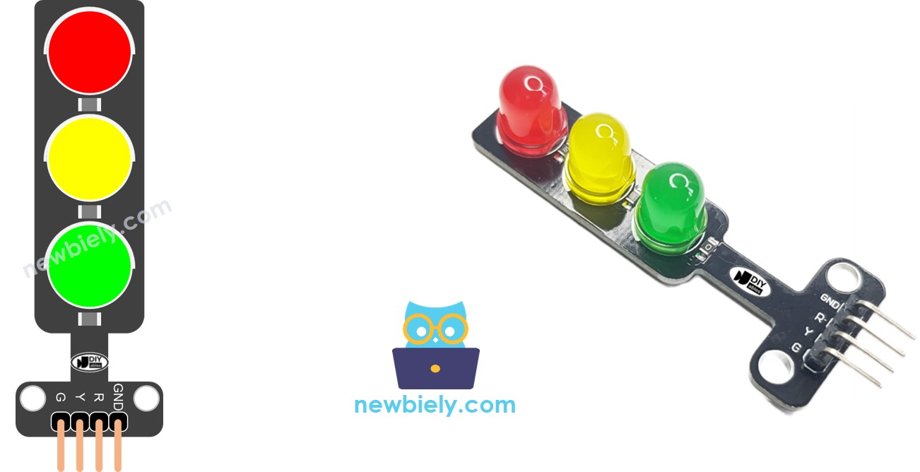
A traffic light module includes 4 pins:
- GND pin: the ground pin; connect it to GND of the ESP32 C3 Super Mini
- R pin: controls the red light; connect it to a digital output of the ESP32 C3 Super Mini
- Y pin: controls the yellow light; connect it to a digital output of the ESP32 C3 Super Mini
- G pin: controls the green light; connect it to a digital output of the ESP32 C3 Super Mini
How It Works
Each light has its own pin, so your code controls each one on its own.
- HIGH: set a pin to HIGH to turn its light on
- LOW: set a pin to LOW to turn its light off
- One at a time: turn one light on and the other two off, like a real traffic light
- Timing: wait for a set time, then move to the next light
Wiring Diagram
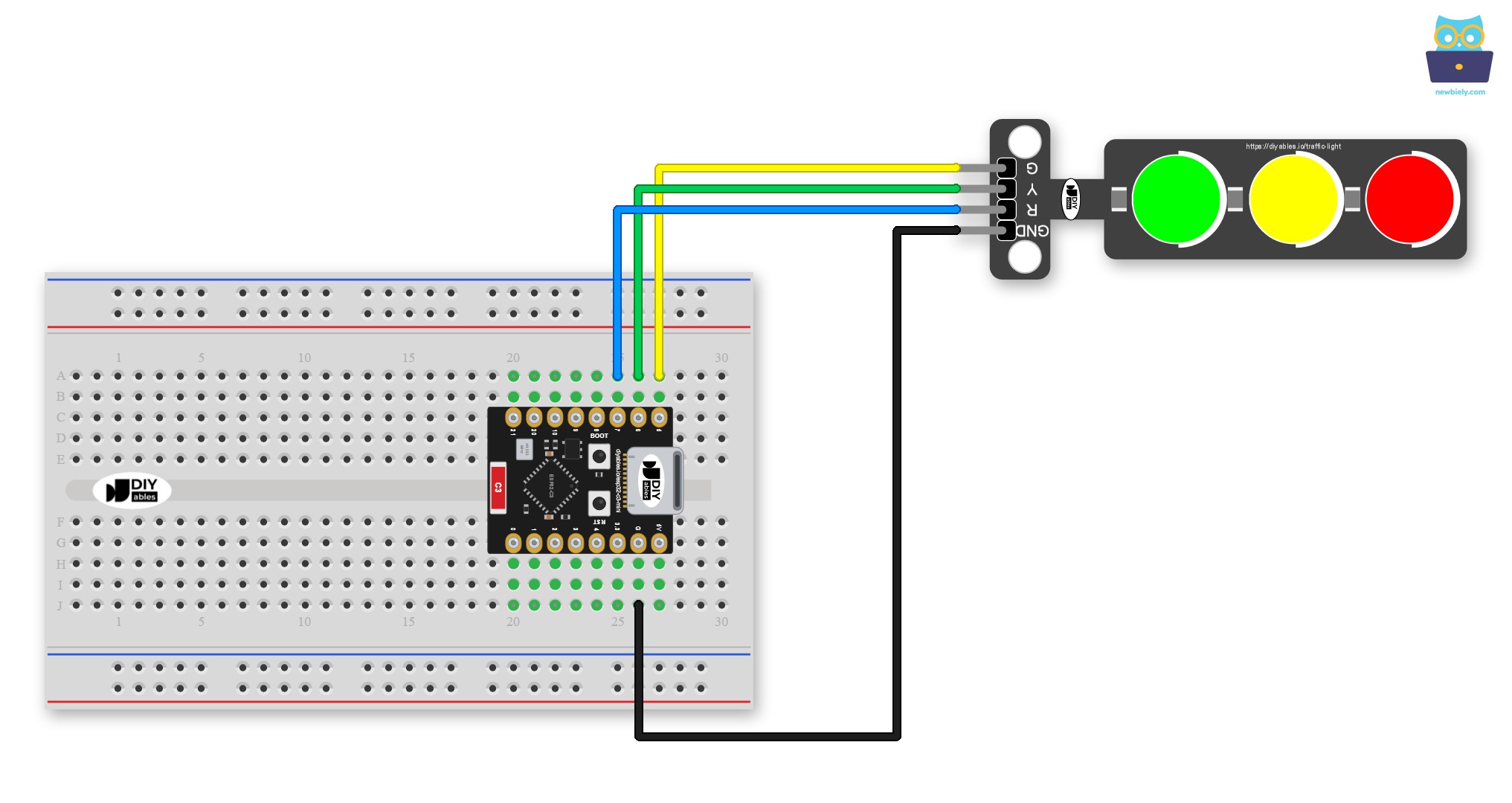
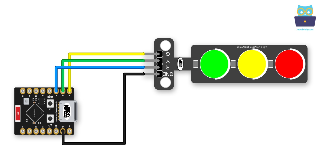
Connect the three signal pins to three GPIO pins, and connect GND to GND.
- Note: Unplug the USB cable while you change the wires.
- Note: Check the GND wire first. A loose GND can make the lights act strangely.
This image is created using Fritzing. Click to enlarge image
Here is the same wiring without a breadboard:
This image is created using Fritzing. Click to enlarge image
| Traffic Light Module Pin | ESP32 C3 Super Mini Pin |
|---|---|
| GND | GND |
| R | GPIO7 |
| Y | GPIO6 |
| G | GPIO5 |
How To Program For Traffic Light Module
The program needs only two steps.
- Set the pins as outputs: Configure the pins to digital output mode with the pinMode() function.
- Turn on a light: Turn on the red light with the digitalWrite() function.
ESP32 C3 Super Mini Code
This first sketch controls each light directly.
What This Code Does:
- Sets GPIO7, GPIO6 and GPIO5 as outputs
- Turns on the red light for 4 seconds
- Turns on the yellow light for 4 seconds
- Turns on the green light for 4 seconds, then starts again
Detailed Instructions
Follow these steps to run the code.
- New to ESP32 C3 Super Mini? Complete our Getting Started with ESP32 C3 Super Mini tutorial first to set up your development environment.
- Wire it: Connect the parts as shown in the wiring diagram above.
- Connect the board: Plug the ESP32 C3 Super Mini into your computer with a USB Type-C cable.
- Open the IDE: Launch the Arduino IDE on your computer.
- Pick the board: Make sure ESP32 C3 Super Mini is selected in Tools > Board.
- Pick the port: Choose the COM port of your board.
- Add the code: Copy the code above and paste it into the Arduino IDE.
- Upload: Click the Upload button in the Arduino IDE.
- Check the result: Watch the traffic light module change from red to yellow to green.
- Serial Monitor: You do not need it here, because these sketches print nothing. If you add Serial code later, use a baud rate of 115200.
- Pro Tip: Change RED_TIME, YELLOW_TIME and GREEN_TIME at the top of the code to try different timings.
Real traffic lights can work differently, depending on the design, the technology and the region. This project only shows the general idea of how traffic lights manage traffic and keep roads safe.
The code above controls each light directly. Now, let's make the code better.
ESP32 C3 Super Mini Code Optimization
Each version below does the same job with cleaner code. These versions use 2 seconds for red, 1 second for yellow and 2 seconds for green.
- Use a function: A function called trafic_light_on() turns on one light and turns off the other two.
- Use a for loop: A for loop goes through the three lights, so loop() becomes much shorter.
- Use millis() instead of delay(): The board does not stop and wait, so it can do other work while the lights run.
Application Ideas
An ESP32 C3 Super Mini traffic light can do more than copy a road signal.
- Intersection Model: Build a small road crossing with your own light timings.
- Machine Status Light: Show idle with green, warning with yellow and fault with red.
- Pedestrian Crossing: Add a button so people can ask for a red light.
- Noise Level Warning: Show quiet, loud and too loud in a classroom.
- Teaching Tool: Show students how timing and non-blocking code work.
Challenge Yourself
Try these ideas to build on your traffic signal project.
- Easy: Keep the yellow light on for 3 seconds and the green light on for 8 seconds.
- Medium: Add a button that switches to the red light right away.
- Medium: Print the name of the current light to the Serial Monitor at 115200 baud.
- Advanced: Add a sensor reading to the millis() version while the lights keep running.