
ESP32 C3 Super Mini - Keypad - Electromagnetic Lock
Build a simple password door lock with an ESP32 C3 Super Mini, a 3x4 keypad and an electromagnetic lock. When the password is correct, the ESP32 C3 Super Mini opens the lock through a relay. A second sketch opens it for 5 seconds and then locks it again, without using the delay() function.
In this tutorial, you'll learn:
- How to wire a keypad, a relay and an electromagnetic lock to the ESP32 C3 Super Mini
- How to read a password from the keypad
- How to accept multiple passwords in one sketch
- How to unlock the door when the password is correct
- How to lock the door again after 5 seconds, without delay()
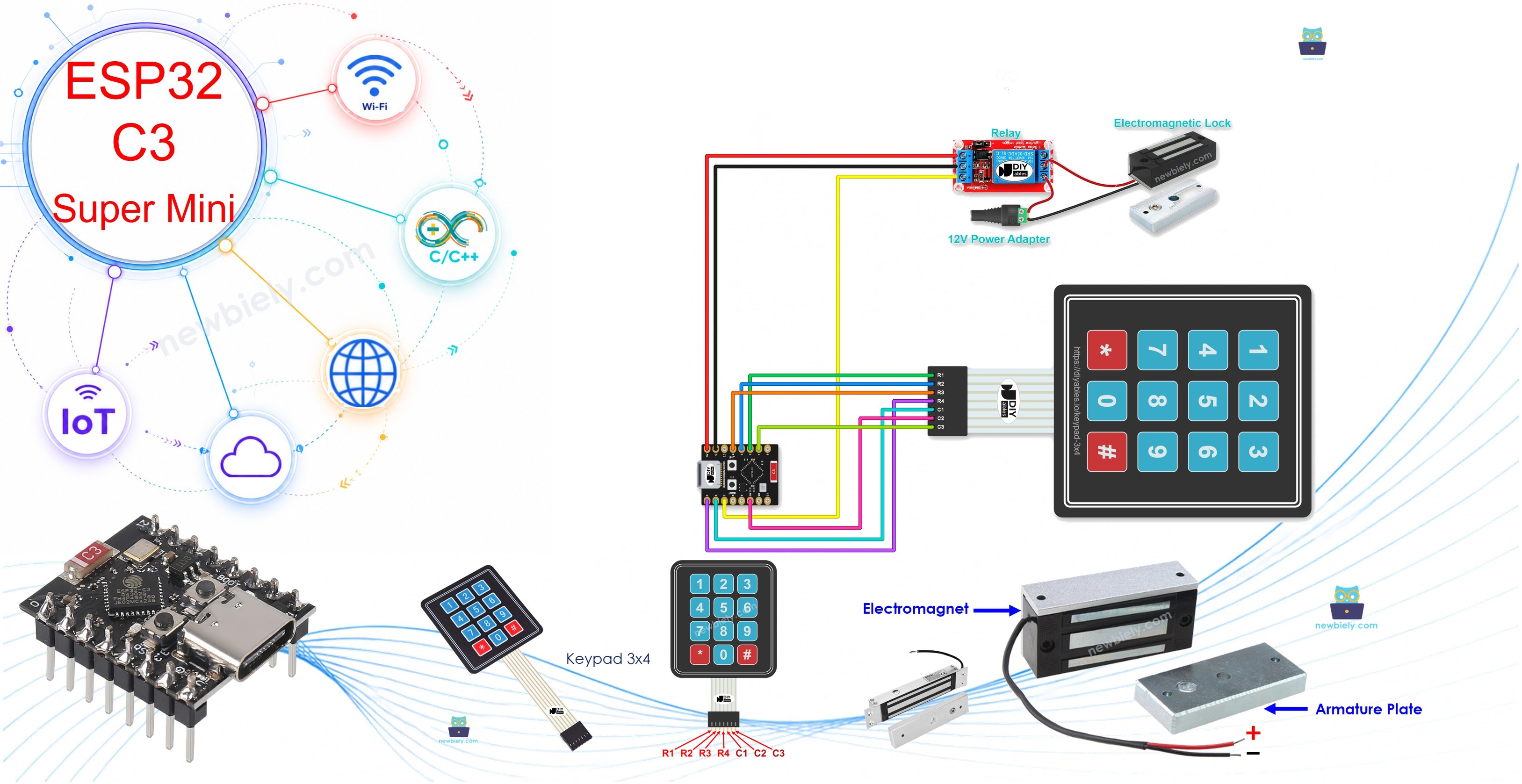
Hardware Preparation
Or you can buy the following kits:
| 1 | × | DIYables Sensor Kit (18 sensors/displays) |
Additionally, some of these links are for products from our own brand, DIYables .
Overview of Keypad and Electromagnetic Lock
A keypad is an input pad that sends key presses to the board, and an electromagnetic lock is a magnet that holds a door closed while it has power.
Key Features:
- Keypad: 12 keys in 4 rows and 3 columns, with no power pin.
- Electromagnetic lock: No moving parts. It locks with magnetic force.
- Relay: Lets the 3.3V GPIO pin switch the 12V lock power safely.
- Fail-safe: The electromagnetic lock opens when its power is cut.
Technical Specifications:
- Keypad pins: 7 (R1, R2, R3, R4, C1, C2, C3).
- Lock power: 12V in this tutorial, from the power adapter.
- Relay module power: 5V from the board.
- Control logic: Pin HIGH = lock powered = door locked. Pin LOW = lock not powered = door unlocked.
Pinout:
- R1 to R4 pins: The 4 row pins of the keypad.
- C1 to C3 pins: The 3 column pins of the keypad.
- Relay IN pin: The control signal from the ESP32 C3 Super Mini.
- Relay COM and NO pins: The switch that carries the 12V lock power.
- Lock wires: Two wires that take the 12V power.
New to these parts? Learn more about their pinouts, how they work and how to program them here:
- ESP32 C3 Super Mini - Keypad tutorial
Wiring Diagram
Connect the keypad to 7 GPIO pins, and connect the lock through the relay.
- Note: Never connect the electromagnetic lock directly to a GPIO pin. Always use the relay.
- Note: Disconnect all power before you change any wire.
- Note: Check that your power adapter matches the voltage and current of your lock.
- Note: Do not use GPIO8 (built-in LED), GPIO9 (boot pin), GPIO20 or GPIO21 (Serial Monitor UART).
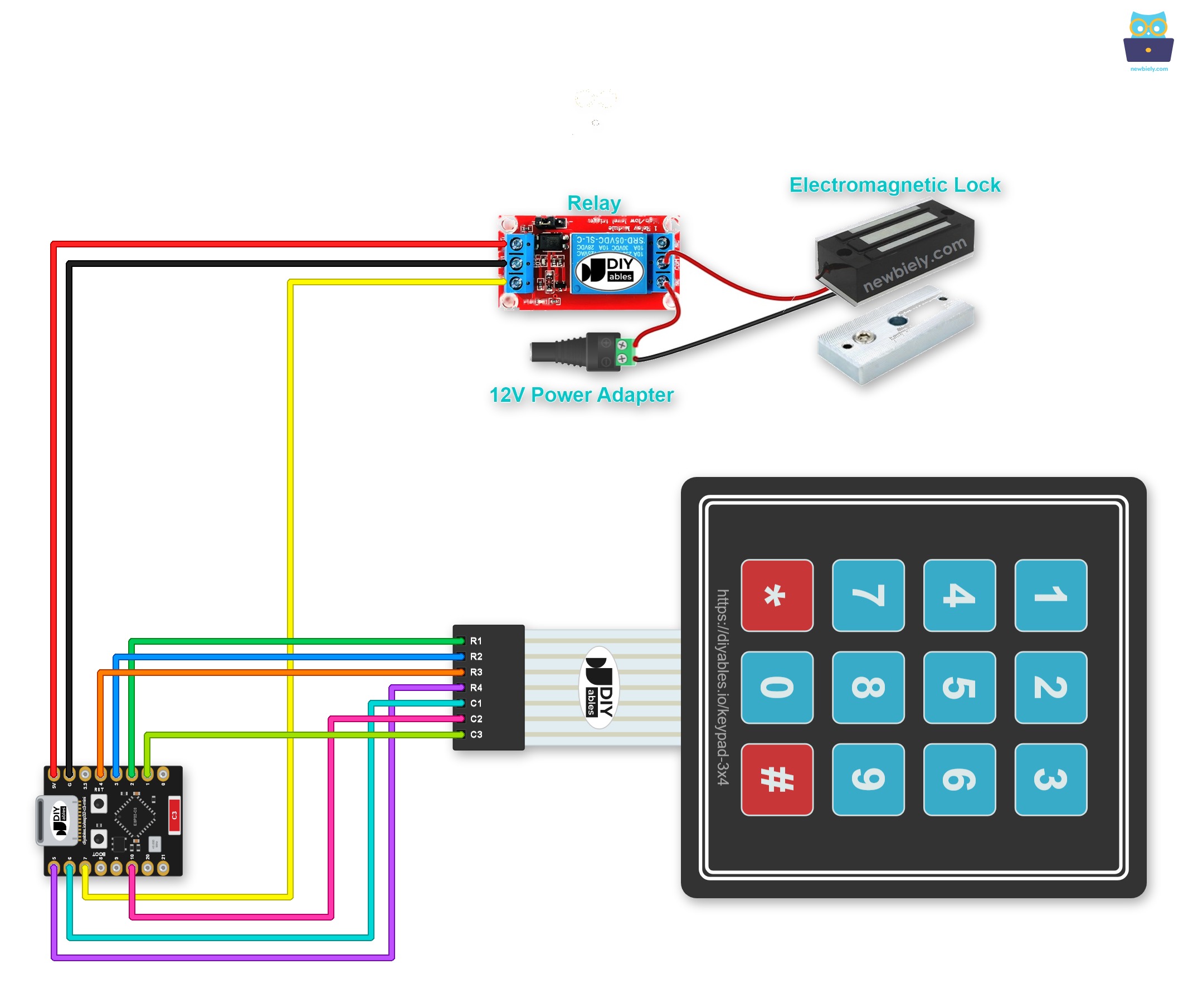
This image is created using Fritzing. Click to enlarge image
| Component Pin | ESP32 C3 Super Mini Pin |
|---|---|
| Keypad R1 | GPIO2 |
| Keypad R2 | GPIO3 |
| Keypad R3 | GPIO4 |
| Keypad R4 | GPIO5 |
| Keypad C1 | GPIO6 |
| Keypad C2 | GPIO10 |
| Keypad C3 | GPIO1 |
| Relay IN | GPIO7 |
| Relay VCC | 5V |
| Relay GND | GND |
The 12V side does not touch the board:
| Lock Circuit Pin | Connect To |
|---|---|
| Relay COM | 12V Power + |
| Relay NO | Lock Wire 1 |
| Lock Wire 2 | 12V Power - |
※ NOTE THAT:
The relay stays on GPIO7, the same pin as the electromagnetic lock tutorial. So the keypad columns here are GPIO6, GPIO10 and GPIO1, which is a little different from the keypad tutorial.
WARNING
The ESP32 C3 Super Mini works at 3.3V logic only. Never connect a keypad pin to 5V or to 12V. It can damage the board.
ESP32 C3 Super Mini Code - Unlock the Electromagnetic Lock if the Password Is Correct
This sketch opens the electromagnetic lock when you type a correct password.
What This Code Does:
- Locks the door at startup by setting GPIO7 HIGH.
- Saves 3 passwords: 1234, 56789 and 901234.
- Adds each pressed key to a String called the input password.
- Checks the input password when you press "#".
- Sets GPIO7 LOW to unlock the door if the password is correct.
Detailed Instructions
- New to ESP32 C3 Super Mini? Complete our Getting Started with ESP32 C3 Super Mini tutorial first to set up your development environment.
- Wire the parts: Follow the wiring diagram and the tables above.
- Connect the board: Plug the ESP32 C3 Super Mini into your PC with a USB Type-C cable.
- Open the IDE: Start the Arduino IDE on your PC.
- Select the board: Make sure ESP32 C3 Super Mini is selected in Tools > Board.
- Select the port: Pick the COM port of your board in Tools > Port.
- Open Library Manager: Click the Libraries icon on the left bar of the Arduino IDE.
- Search for the library: Type keypad, then find the Keypad library by Mark Stanley, Alexander Brevig.
- Install the library: Click the Install button.
- Search for Keypad created by Mark Stanley, Alexander Brevig and click the Install button.
- Copy the code: Copy the code above and open it in the Arduino IDE.
- Upload the code: Click the Upload button to send the code to the ESP32 C3 Super Mini.
- Open Serial Monitor: Set the baud rate to 115200.
- Try a wrong password: Press 8123 and then press #.
- Try the right password: Press 1234 and then press #.
- Check the result: Read the Serial Monitor and look at the state of the electromagnetic lock.
- Pro Tip: This sketch never locks the door again by itself. Press the reset button on the board to lock it again.
Code Explanation
The authorized passwords are saved in the code, and the typed keys are kept in a String called the input password.
- Normal key: The key is added to the end of the input password.
- "*" key: The input password is cleared. Use it to start or restart typing.
- "#" key: The input password is compared with the saved passwords.
- Match: The ESP32 C3 Super Mini sets the relay pin LOW, and the electromagnetic lock opens.
- After "#": The input password is cleared for the next try, whether it was correct or not.
ESP32 C3 Super Mini Code - Unlock the Electromagnetic Lock for a Period of Time
This sketch opens the electromagnetic lock for 5 seconds when the password is correct, and then locks it again.
What This Code Does:
- Uses the same keypad code and the same 3 passwords as the first sketch.
- Controls the relay on GPIO7 with the ezOutput library.
- Starts a 5-second pulse with relay.pulse() when the password is correct.
- Keeps reading the keypad during those 5 seconds, because it does not use delay().
- Sets the unlock time with UNLOCK_TIME, in milliseconds.
Detailed Instructions
- Install the library: Open the Library Manager, search for ezOutput, then click Install.
- Search for ezOutput created by ArduinoGetStarted.com and click the Install button.
- Upload the code: Copy the code above, paste it into the Arduino IDE, and click Upload.
- Open Serial Monitor: Set the baud rate to 115200.
- Test it: Press 1234 and then press #.
- Watch the lock: The door opens, and it locks again after 5 seconds.
- Pro Tip: The ezOutput library manages the time without blocking the code. Change UNLOCK_TIME to keep the door open for longer.
Application/Project Ideas
A keypad and an electromagnetic lock on the ESP32 C3 Super Mini can protect many real doors.
- Home Door Lock: Open a front or back door with a PIN code.
- Office Access: Give each person their own password for one room.
- Tutorial Security: Keep tools and machines behind a locked door.
- Storage Cabinet: Lock a cabinet or a tool locker with a small electromagnetic lock.
- Exit Timer: Open a door for a few seconds, and then lock it again by itself.
Challenge Yourself
Try these small projects to improve your ESP32 C3 Super Mini keypad electromagnetic lock.
- Easy: Change the passwords to your own codes and test them.
- Easy: Change UNLOCK_TIME so the door stays open for 10 seconds.
- Medium: Add a buzzer that beeps when the password is wrong.
- Medium: Block the keypad for 30 seconds after three wrong tries.
- Advanced: Save the passwords in flash memory, and add a key sequence to change them.
- Advanced: Use the WiFi of the ESP32 C3 Super Mini to send you an alert after many wrong tries.