
ESP32 C3 Super Mini - RS232
RS232 lets the ESP32 C3 Super Mini talk to older serial devices over a long cable. A small TTL to RS232 module does the voltage conversion for you. This tutorial shows the wiring and the code in simple steps.
In this tutorial, you'll learn:
- What a TTL to RS232 module is and why you need one
- How to wire the module to the ESP32 C3 Super Mini
- How to use a second hardware serial port (UART1) so the Serial Monitor keeps working
- How to program the ESP32 C3 Super Mini to read data from RS232
- How to program the ESP32 C3 Super Mini to send data to RS232
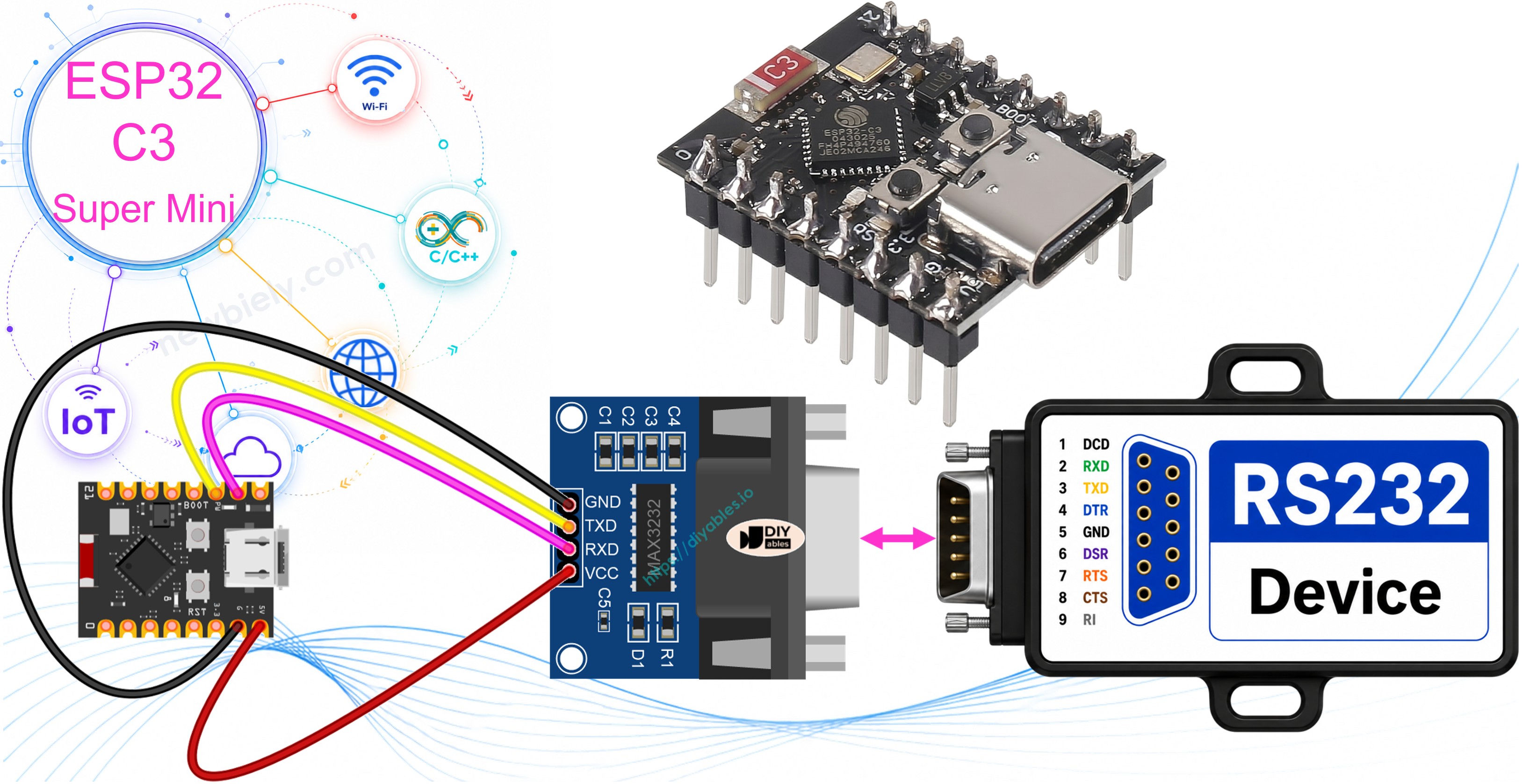
Hardware Preparation
Or you can buy the following kits:
| 1 | × | DIYables Sensor Kit (18 sensors/displays) |
Additionally, some of these links are for products from our own brand, DIYables .
Overview of TTL to RS232 Module
A TTL to RS232 module is a small board that converts the TTL signal of the ESP32 C3 Super Mini into an RS232 signal, and back again.
Why you need it:
- The TX and RX pins of the ESP32 C3 Super Mini use TTL levels (0V and 3.3V)
- A TTL signal is weak and cannot travel far
- RS232 uses much bigger voltages, so it works over a long cable
- The module sits between the board and the serial device and translates both ways
Key Features:
- Two-way conversion: TTL to RS232 and RS232 to TTL
- Uses a MAX3232-type chip, which works at 3.3V logic
- DB9 female connector for the RS232 side
- Simple 4-pin TTL side: VCC, GND, RXD, TXD
- No code library needed - it is a plain hardware converter
Technical Specifications:
- Supply voltage: 3.3V or 5V
- Logic level on the TTL side: follows VCC, so use 3.3V for this board
- Typical baud rate: 9600 (up to 115200 works fine)
- Data format: 8 data bits, no parity, 1 stop bit (SERIAL_8N1)
- Cable length: up to about 15 m at 9600 baud
WARNING
Raw RS232 voltages swing to about +/-12V. Never connect a DB9 line straight to a GPIO pin - it will destroy the ESP32 C3 Super Mini. You must always use a MAX3232-type level converter module, and power its TTL side from the 3.3V pin so its logic matches the board.
Pinout
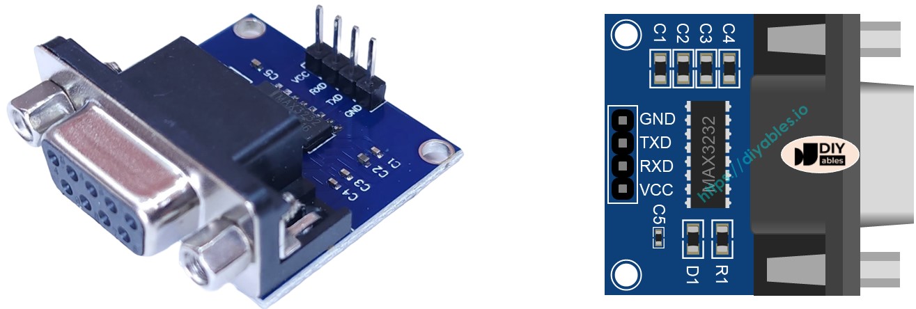
The TTL to RS232 module has two sides: one for the ESP32 C3 Super Mini and one for the serial device.
- VCC: Power pin - connect to the 3.3V pin of the ESP32 C3 Super Mini
- GND: Ground pin (0V) - connect to GND
- RXD: Data input of the module - connect to a TX pin of the ESP32 C3 Super Mini
- TXD: Data output of the module - connect to an RX pin of the ESP32 C3 Super Mini
- DB9 connector: The RS232 side - a female D-Sub plug that goes to your serial device
Wiring Diagram
Connect the module to GPIO6 and GPIO7, and keep the Serial Monitor pins free.
- Note: GPIO20 and GPIO21 are the UART the Serial Monitor uses. Do NOT use them for the module.
- Note: Power the module from 3.3V only. 5V on the TTL side can push 5V into a GPIO pin.
- Note: TX goes to RXD and RX goes to TXD. The lines always cross.
- Note: GND of the module and GND of the board must be joined, or the data will be noise.
| TTL to RS232 Module Pin | ESP32 C3 Super Mini Pin |
|---|---|
| VCC | 3.3V |
| GND | GND |
| RXD | GPIO6 (TX of UART1) |
| TXD | GPIO7 (RX of UART1) |
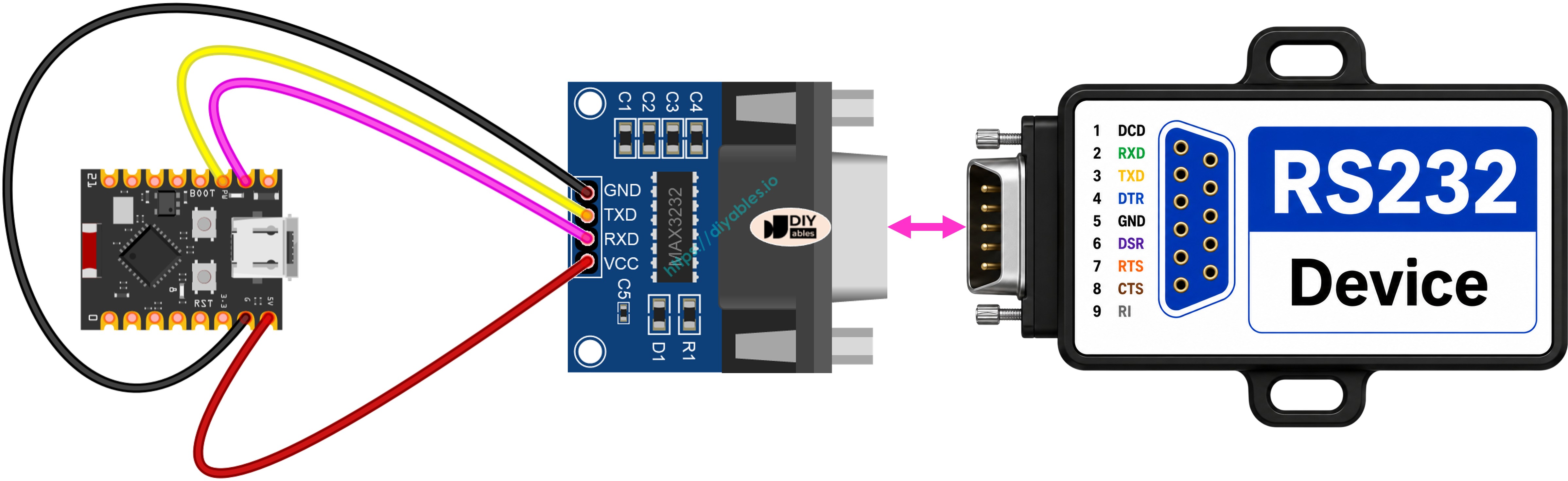
This image is created using Fritzing. Click to enlarge image
How To Program ESP32 C3 Super Mini to use the RS232 module
The ESP32 C3 Super Mini has more than one hardware UART, so the module gets its own port.
- Important: SoftwareSerial does not exist on the ESP32 C3 Super Mini. Use HardwareSerial instead.
- Why: UART0 (GPIO20 / GPIO21) is already busy with the USB Serial Monitor.
- Solution: Create a second port with HardwareSerial rs232Serial(1); and give it free pins.
- Include the header and define the serial pins:
- Initialize the two serial interfaces:
※ NOTE THAT:
The two baud rates are different on purpose. 115200 is for the Serial Monitor on your PC. 9600 is the speed of the RS232 device. Both numbers must match the other side of that link.
- To read data coming from RS232, you can use the following functions:
- To write data to RS232, you can use the following functions:
- Call each of them on rs232Serial, for example rs232Serial.read() or rs232Serial.println("Hello").
- And more functions to use with RS232 in Serial reference
ESP32 C3 Super Mini Code for RS232
This sketch echoes every RS232 character back to the sender and also prints it on the Serial Monitor.
What This Code Does:
- Opens the Serial Monitor at 115200 baud
- Opens UART1 at 9600 baud on GPIO7 (RX) and GPIO6 (TX)
- Checks if a new character arrived from the RS232 side
- Sends that character straight back to the RS232 device
- Prints the same character on your Serial Monitor so you can see it
Detailed Instructions
- New to ESP32 C3 Super Mini? Complete our Getting Started with ESP32 C3 Super Mini tutorial first to set up your development environment.
- Wire the module: Follow the table above - VCC to 3.3V, GND to GND, RXD to GPIO6, TXD to GPIO7
- Connect the board: Plug the ESP32 C3 Super Mini into your PC with a USB Type-C cable
- Open the IDE: Copy the code above and paste it into the Arduino IDE
- Select your board: Make sure ESP32 C3 Super Mini is selected in Tools > Board.
- Choose your port: Pick the correct COM port in Tools > Port
- Upload the code: Click the Upload button and wait for "Done uploading"
- Open Serial Monitor: Set the baud rate to 115200
- Send some text: Type into your serial terminal program and watch it appear
- Pro Tip: If you see nothing, swap the RXD and TXD wires first - crossed lines are the most common mistake.
Testing
You can test data moving in both directions between your PC and the ESP32 C3 Super Mini over RS232.
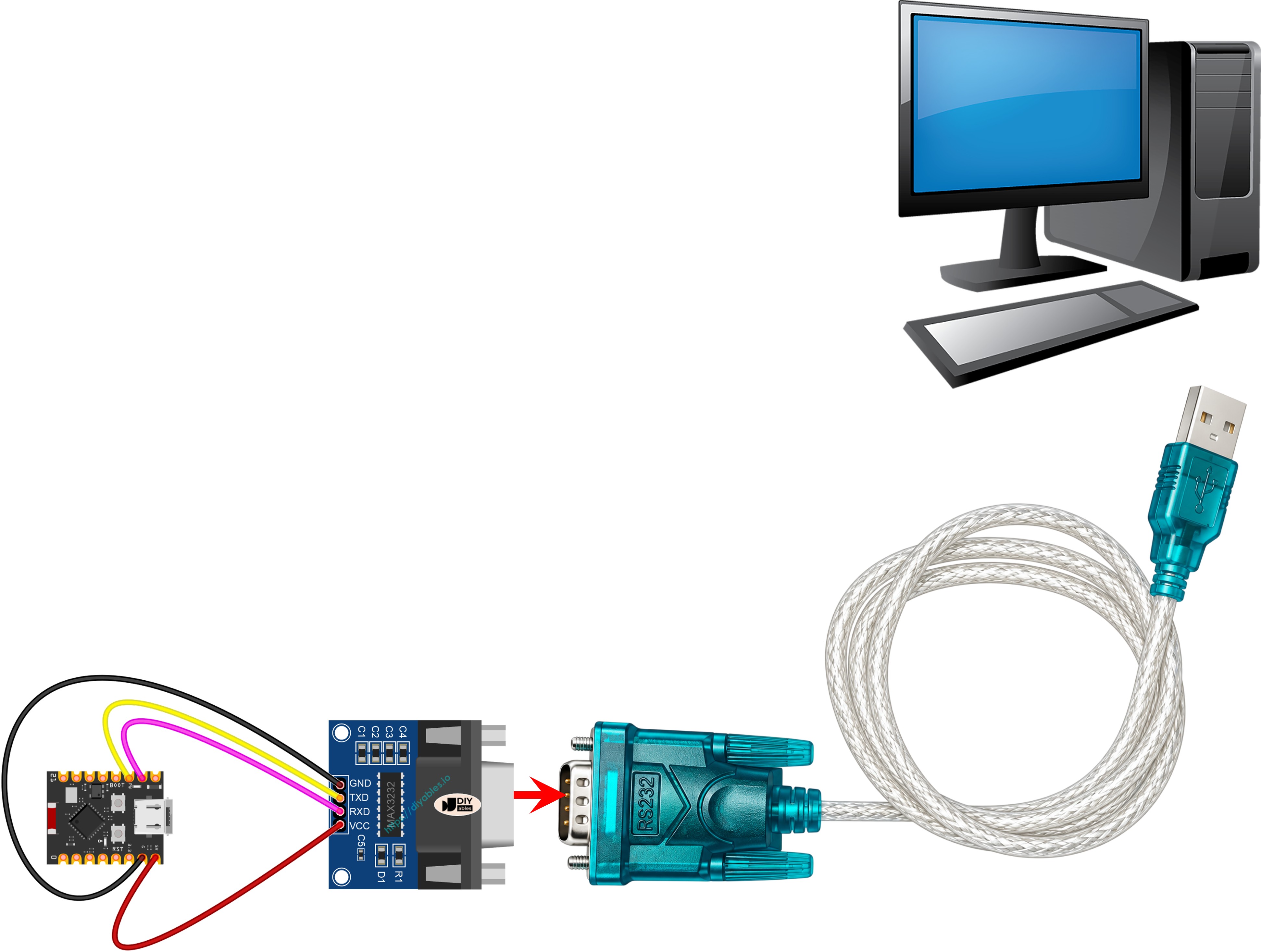
- Connect the module to your PC using an RS232-to-USB cable, as shown in the image below:
- Open the Serial Terminal Program and set the serial parameters (COM port, 9600 baud, 8N1).
- Type some data in the Serial Terminal to send it to the ESP32 C3 Super Mini.
- If the test works, you will see the same data echoed back in the Serial Terminal.
- At the same time, the Arduino IDE Serial Monitor shows what the board received.
Serial Monitor Output
Here is what the Arduino IDE Serial Monitor shows while you type into the RS232 terminal.
Application and Project Ideas
RS232 is still everywhere in machines and lab gear, so this skill is very useful.
- Industrial machine reader: Read status messages from a PLC or a CNC machine
- Barcode scanner logger: Capture codes from an RS232 barcode gun and save them
- Weighing scale display: Read the weight from a lab scale and show it on an OLED
- GPS receiver link: Take NMEA data from an older RS232 GPS unit
- Long-distance sensor link: Move serial data 15 m without losing it
- Legacy device bridge: Put RS232 data on WiFi so a modern app can use it
Challenge Yourself
Try these small upgrades to learn more about RS232 on the ESP32 C3 Super Mini.
- Easy: Change the RS232 baud rate to 19200 on both the board and the terminal
- Easy: Send a "Hello from ESP32 C3 Super Mini" message once per second
- Medium: Read a whole line with readStringUntil('\n') instead of one character
- Medium: Turn the built-in LED on GPIO8 on for a moment every time a byte arrives
- Advanced: Make the board answer simple text commands like LED ON and LED OFF
- Advanced: Forward everything from RS232 to a web page over WiFi