
ESP32 C3 Super Mini - Joystick - Servo Motor
Build a simple joystick servo motor project with your ESP32 C3 Super Mini. The joystick moves two servo motors, or a pan-tilt kit, and each axis controls one servo on its own.
In this tutorial, you'll learn:
- How to wire a joystick and two servo motors to ESP32 C3 Super Mini
- How to make the servo motors follow the joystick's thumb
- How to use the joystick to send up, down, left and right commands to the servo motors
- How to bring the servo motors back to the center with the joystick's button
- Why the servo motors may not move in exact proportion to the joystick
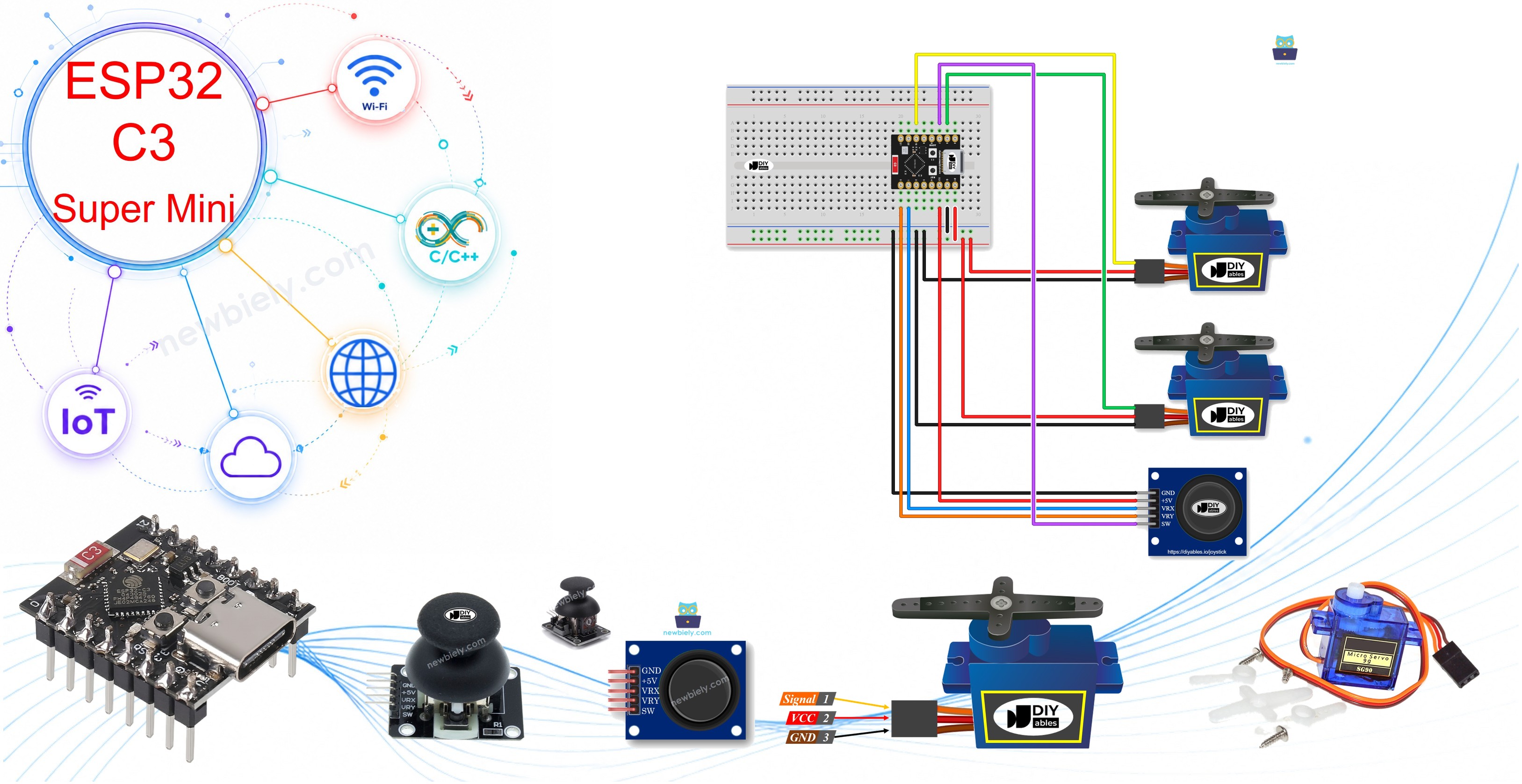
Hardware Preparation
Or you can buy the following kits:
| 1 | × | DIYables Sensor Kit (18 sensors/displays) |
Additionally, some of these links are for products from our own brand, DIYables .
Buy Note: For controlling multiple servo motors, use the PCA9685 16 Channel PWM Servo Driver Module to save MCU pins and simplify wiring.
Overview of Joystick and Servo Motor
A joystick is an input module that gives two analog values, and a servo motor is an actuator that turns to a chosen angle.
Key Features:
- Two potentiometers: The joystick has two built-in potentiometers, square with each other (X-axis and Y-axis).
- Two analog outputs: They give the X-value on the VRX pin and the Y-value on the VRY pin.
- Independent control: The X-value controls servo motor #1 and the Y-value controls servo motor #2.
- Pan-tilt movement: With a pan-tilt kit, the two servo motors together create 3-D movement.
Technical Specifications:
- Joystick values on this board: analogRead() returns 0 to 4095 (12-bit ADC).
- Servo motor angle: 0° to 180°.
- Joystick power: 3.3V.
- Servo motor power: 5V.
Learn the basics first if you do not know these parts yet (pinout, how they work, how to program them):
Two Ways to Use It
This tutorial gives you code for two use cases.
Use case 1: The servo motors follow the joystick's thumb
- Angle: The angles of the servo motors are in proportion to the joystick's X-value and Y-value.
- Release: When you release the thumb, the values go back to the center, and the servo motors go back to the center position.
Use case 2: The joystick sends commands to the servo motors
- Left: Pushing the thumb to the left moves servo motor #1 clockwise, step by step.
- Right: Pushing the thumb to the right moves servo motor #1 anti-clockwise, step by step.
- Up: Pushing the thumb up moves servo motor #2 clockwise, step by step.
- Down: Pushing the thumb down moves servo motor #2 anti-clockwise, step by step.
- Release: When you release the thumb, the servo motors do not go back to the center.
- Press: When you press the joystick's button, the servo motors go back to the center position.
Pinout
These are the pins you will connect in this project.
Joystick:
- GND: Connects to ground (0V).
- VCC: Connects to 3.3V.
- VRX: Analog output for the X-axis.
- VRY: Analog output for the Y-axis.
- SW: Output of the built-in push button. Only the second code uses it.
Each servo motor:
- GND (brown or black): Connects to ground (0V).
- VCC (red): Connects to 5V.
- Signal (yellow or orange): Receives the control signal from the ESP32 C3 Super Mini.
Wiring Diagram
Connect the joystick and the two servo motors to the ESP32 C3 Super Mini as shown below.
- Note: VRX and VRY must use GPIO0 to GPIO4, because only these pins can read analog values on this board.
- Note: Power the joystick from 3.3V, so its outputs stay safe for the GPIO pins.
- Note: Two servo motors can draw a lot of current. If they shake or the board resets, power them from an external 5V supply and connect its GND to the board's GND.
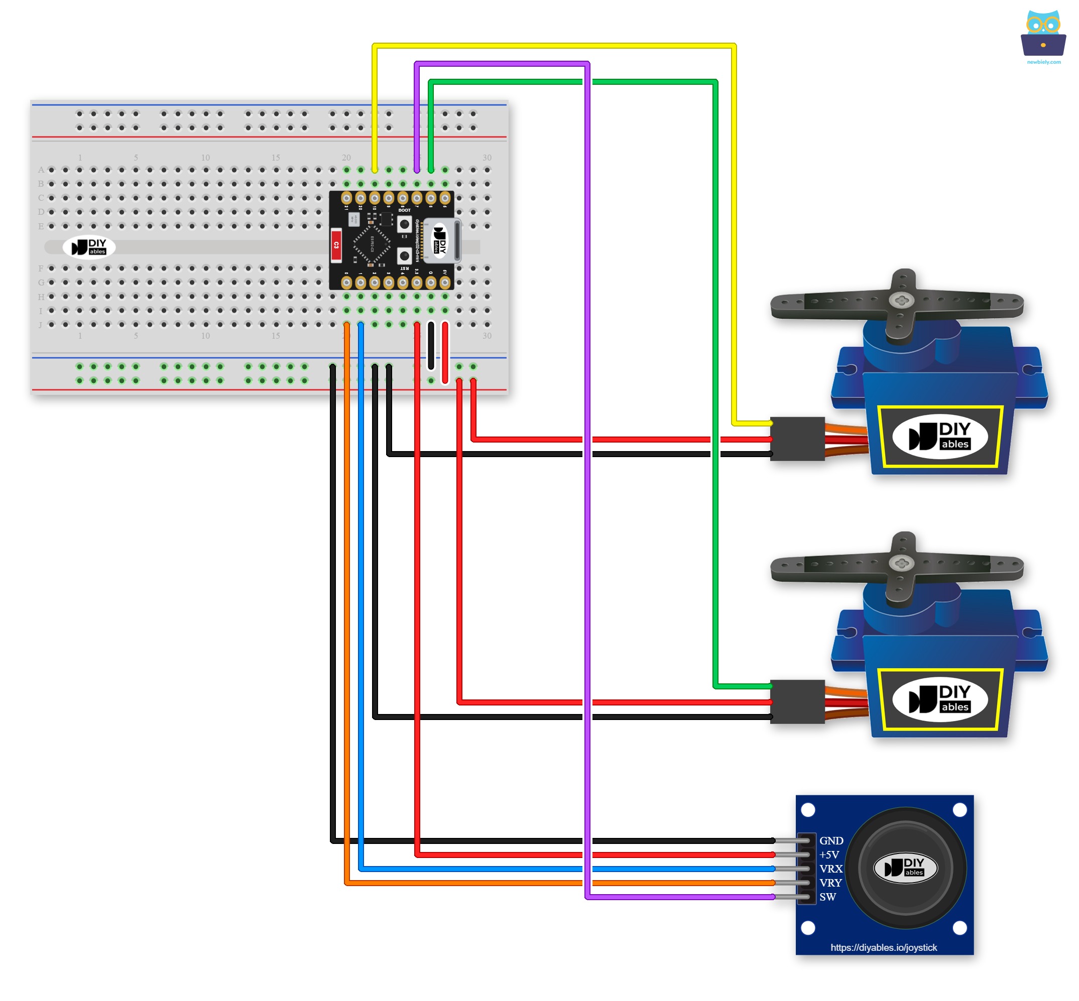
This image is created using Fritzing. Click to enlarge image
No breadboard? The same circuit can be wired without one, as shown below:
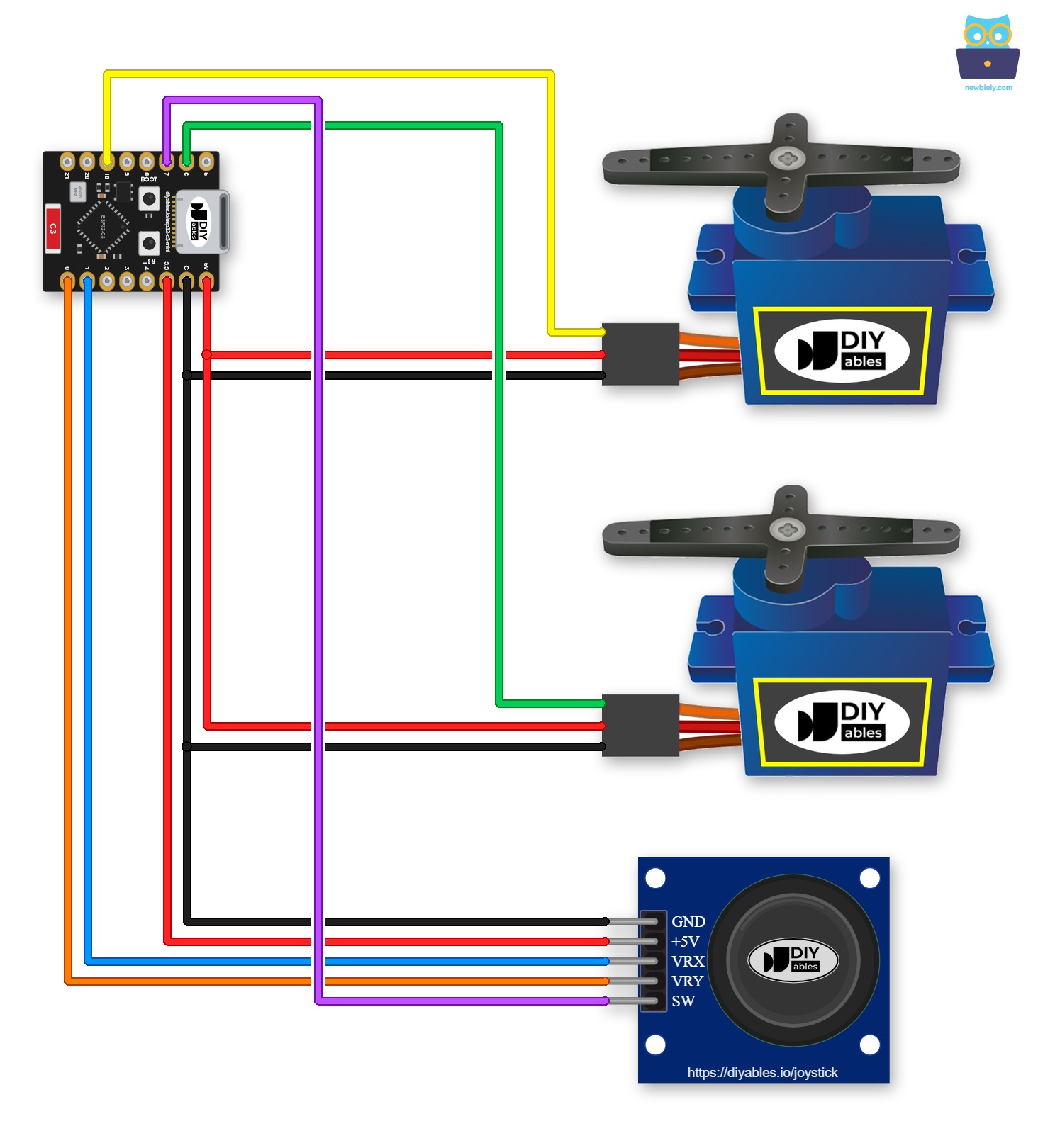
This image is created using Fritzing. Click to enlarge image
| Joystick Pin | ESP32 C3 Super Mini Pin |
|---|---|
| GND | GND |
| VCC | 3.3V |
| VRX | GPIO1 |
| VRY | GPIO0 |
| SW | GPIO7 |
| Servo Motor Pin | ESP32 C3 Super Mini Pin |
|---|---|
| Servo motor #1 GND | GND |
| Servo motor #1 VCC | 5V |
| Servo motor #1 Signal | GPIO10 |
| Servo motor #2 GND | GND |
| Servo motor #2 VCC | 5V |
| Servo motor #2 Signal | GPIO6 |
ESP32 C3 Super Mini Code
There are two sketches below, one for each use case.
ESP32 C3 Super Mini Code - The servo motors rotate according to the movement of the joystick's thumb
This code turns the joystick's position directly into servo motor angles.
What This Code Does:
- Reads the joystick: Reads the X-value on GPIO1 and the Y-value on GPIO0.
- Converts the values: Scales 0-4095 to an angle of 0-180°.
- Moves the servo motors: Writes the angles to servo motor #1 on GPIO10 and servo motor #2 on GPIO6.
- Prints the result: Shows the joystick values and the angles on the Serial Monitor.
Detailed Instructions
Follow these steps to run the first code.
- New to ESP32 C3 Super Mini? Complete our Getting Started with ESP32 C3 Super Mini tutorial first to set up your development environment.
- Wire the components: Follow the wiring diagram above.
- Connect the board: Plug the ESP32 C3 Super Mini into your computer with a USB Type-C cable.
- Open Arduino IDE: Launch the Arduino IDE on your computer.
- Select the board: Make sure ESP32 C3 Super Mini is selected in Tools > Board.
- Select the port: Choose the matching COM port.
- Open Library Manager: Click the Libraries icon on the left bar of the Arduino IDE.
- Search for the library: Type "ESP32Servo" in the search box, then find the servo library by Kevin Harrington, John K. Bennett.
- Install the library: Click the Install button.
- Search for ESP32Servo created by Kevin Harrington,John K. Bennett and click the Install button.
- Copy the code: Copy the above code and open it with Arduino IDE.
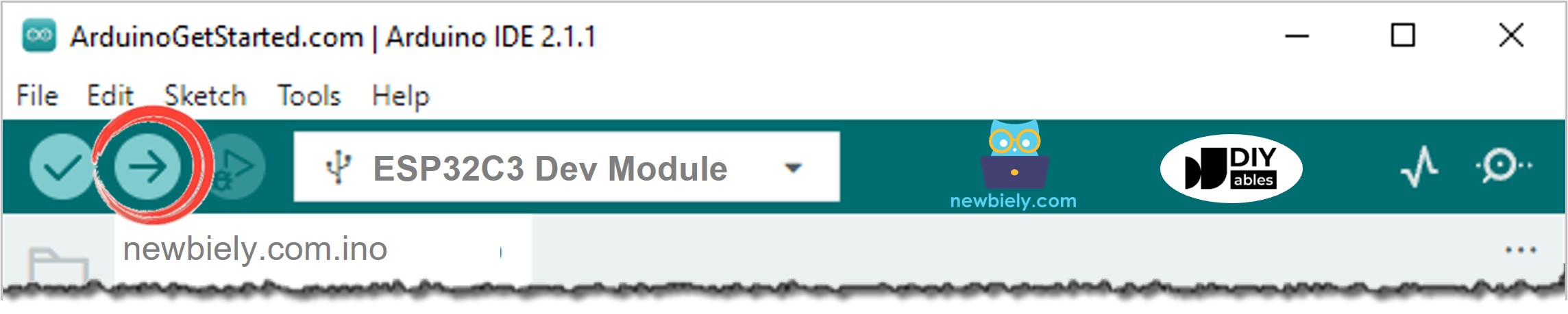
- Upload the code: Click the Upload button to upload the code to the ESP32 C3 Super Mini.
- Open Serial Monitor: Set the baud rate to 115200.
- Move the joystick: Push the joystick in some direction.
- Check the servo motors: See the servo motors rotate.
- Check the result: See the values on the Serial Monitor.
- Pro Tip: Test one servo motor at a time first. A loose wire is much easier to find this way.
You may notice that the servo motor does not move in exact proportion to the joystick. This does not come from the joystick or the servo motor, but from the ADC of the ESP32 C3 Super Mini. The note at the end of this tutorial explains why.
ESP32 C3 Super Mini Code - Use the joystick to command servo motors
This code turns the joystick's position into commands that move the servo motors step by step.
What This Code Does:
- Reads the joystick: Checks the X-value and the Y-value every 100 ms.
- Finds the command: Values below 1000 mean left or up, and values above 3000 mean right or down.
- Moves step by step: Each command changes the angle by 1°, and the servo motors stay where they are after you release the thumb.
- Goes back to the center: Pressing the button on GPIO7 sets both servo motors to 90°.
Detailed Instructions
This code needs one more library.
- New to ESP32 C3 Super Mini? Complete our Getting Started with ESP32 C3 Super Mini tutorial first to set up your development environment.
- Select the board: Make sure ESP32 C3 Super Mini is selected in Tools > Board.
- Open Library Manager: Click the Library Manager icon on the left navigation bar of Arduino IDE.
- Search for the library: Type "ezButton" in the search box, then find the button library by ArduinoGetStarted.com.
- Install the library: Click the Install button.
- Search for ezButton created by ArduinoGetStarted.com and click the Install button.
- Copy the code: Copy the above code and open it with Arduino IDE.
- Upload the code: Click the Upload button to upload the code to the ESP32 C3 Super Mini.
- Open Serial Monitor: Set the baud rate to 115200.
- Move the joystick: Push the joystick in some direction.
- Check the servo motors: See the servo motors rotate.
- Check the result: See the commands and the angles on the Serial Monitor.
- Pro Tip: Change UPDATE_INTERVAL in the code to make the servo motors move faster or slower.
Code Explanation
Read the line-by-line explanation in comment lines of source code!
※ NOTE THAT:
This tutorial uses the analogRead() function to read values from an ADC (Analog-to-Digital Converter) connected to a sensor or component. The ESP32 C3 Super Mini's ADC is suitable for projects that do not require high accuracy. However, for projects needing precise measurements, keep the following in mind:
- The ESP32 C3 Super Mini's ADC is not perfectly accurate and might require calibration for correct results. Each ESP32 C3 Super Mini board can vary slightly, so calibration is necessary for each individual board.
- Calibration can be challenging, especially for beginners, and might not always yield the exact results you want.
For projects requiring high precision, consider using an external ADC (e.g ADS1115) with the ESP32 C3 Super Mini or using another board with a more reliable ADC. If you still want to calibrate the ESP32 C3 Super Mini's ADC, refer to the ESP32 ADC Calibration Driver.
Application and Project Ideas
A joystick and two servo motors are a good base for many projects.
- Pan-Tilt Camera: Aim a small camera left, right, up and down by hand.
- Robot Arm Joint: Move two joints of a small robot arm with one thumb.
- Laser Pointer Turret: Point a low-power laser at a target on the wall.
- Sensor Scanner: Turn a distance sensor to look in any direction.
- Model Control: Move the parts of a model crane or a model boat.
Challenge Yourself
Try these ideas to grow your ESP32 C3 Super Mini joystick servo motor skills.
- Easy: Swap the two axes, so the X-value controls servo motor #2.
- Easy: Change the angle range from 0-180° to 45-135°.
- Medium: Add a dead zone, so small movements near the center do not move the servo motors.
- Medium: Stop the angles in the command code from going below 0° or above 180°.
- Advanced: Save the current angles when the button is held down, and go back to them later.