
ESP32 C3 Super Mini - PC817 Optocoupler: Monitor 12V/24V DC Input Signal
The ESP32 C3 Super Mini is small enough to hide inside a project box, but every one of its GPIO pins tops out at 3.3V DC - so a 12V DC or 24V DC line coming from a car, a doorbell or a machine panel would destroy the board the moment you touched it to a pin. A PC817 optocoupler isolation module is the cheap ready-made part that fixes this, and it is barely bigger than the board itself.
Most of the time the real question is not "is a signal present?" but "is that piece of equipment actually running right now?" - is the pump turning, did the chime get its command, is the heater still drawing power. A PC817 module tapped across a 12V or 24V device answers exactly that, and the ESP32 C3 Super Mini is small enough to leave inside the equipment answering it forever.
In this tutorial, you'll learn:
- What a PC817 optocoupler module is and how it isolates your ESP32 C3 Super Mini from 12V DC and 24V DC
- How to measure the line you want to watch first, then buy the 3-5V, 12V or 24V module that matches it
- How to wire the module's screw terminals and output header to the ESP32 C3 Super Mini
- How to tap the module across equipment that is already installed, so you can monitor whether it is on or off
- How to find out whether your module reads active-LOW or active-HIGH, and flip it with one constant in the code
- How to build the same input from the bare PC817 chip and your own resistor, if you would rather
- Why the 12V/24V ground must never touch your ESP32 C3 Super Mini GND
Why the ESP32 C3 Super Mini Needs a PC817
- 3.3V logic only: This board is a 3.3V design and is not 5V tolerant, so a 12V DC or 24V DC wire is far outside what a GPIO pin can survive
- No shared wiring: The PC817 passes the signal across as light, so no current from the 12V/24V circuit ever reaches the board
- Tiny footprint: A single-channel PC817 module sits next to the ESP32 C3 Super Mini in an enclosure that a full-size board would never fit in
- Cheap enough to retrofit: Both parts cost so little that you can leave one permanently wired inside existing 12V equipment
- Just a digital read: Once the module is in place, your code only calls digitalRead() - no library, no analog maths
Hardware Preparation
Or you can buy the following kits:
| 1 | × | DIYables Sensor Kit (18 sensors/displays) |
Additionally, some of these links are for products from our own brand, DIYables .
Note: buy ONE module - the variant that matches the line you are going to watch. The next section shows you how to work out which one that is.
How a PC817 Optocoupler Module Works
A PC817 optocoupler isolation module is a small board built around the 4-pin PC817 chip. Inside that chip, an infrared LED faces a phototransistor across an insulating gap: current through the LED makes light, the light switches the transistor on, and that is the whole trick. Because the signal crosses as light instead of electricity, the 12V/24V side and the ESP32 C3 Super Mini side stay electrically separate.
What the module adds around the chip is the part that saves you work: the series resistor for the input LED is already fitted, the input arrives on screw terminals that take field wire directly, and a status LED on the input side shows you at a glance when the line is energised. Modules come in 1, 2, 4 and 8 channel versions.
Key Features of the PC817 inside the module:
- Isolation voltage: 5000 Vrms for 1 minute between the input side and the output side
- Input LED: about 1.2 V forward voltage, 20 mA continuous maximum, with 5-20 mA as the normal working range
- Output transistor: 35 V maximum collector-emitter voltage, 50 mA maximum collector current, 150 mW dissipation
- Current Transfer Ratio (CTR): 50% to 600% depending on the rank stamped on the part (rank A 80-160%, B 130-260%, C 200-400%, D 300-600%)
- Speed: roughly 4 us rise time and 3 us fall time, which is instant for anything a human or a machine lamp does
- Temperature range: -30 C to +100 C
Why this suits ESP32 C3 Super Mini beginners:
- Nothing to calculate - the module's resistor was sized at the factory for its input voltage
- There is nothing to calibrate and nothing to configure
- A wiring mistake on the 12V/24V side stops at the module instead of reaching your board
- Screw terminals mean you can land the field wires of installed equipment without a breadboard anywhere near them
Which Optocoupler Module Do I Need? Measure the Line First
Almost everything on this page is a retrofit - you are watching a chime, a pump or a panel lamp that somebody else installed, so the honest answer to "which module?" starts with "I do not know yet, let me measure". Do that before you order anything.
Measuring the line, in three steps:
- Set a multimeter to DC volts and put the black probe on the negative or return terminal of the device you want to watch
- Put the red probe on the positive or switched terminal, then make the device turn on - press the doorbell button, let the thermostat call the pump, whatever normally drives it
- Read the voltage while it is on. That number, not the label on the power brick, is what you are buying a module for
| What the meter reads while the device is on | Buy this module | Typical sources |
|---|---|---|
| Around 12 V DC | 12V module | doorbell chimes, garage-door controllers, car circuits, small pumps and fans |
| Around 24 V DC | 24V module | machine panel lamps, contactor and solenoid coils, PLC outputs, HVAC controls |
| 3.3 V or 5 V DC | 3-5V module | logic outputs, sensor boards, the control board inside an appliance |
Why the variant matters so much: the module's series resistor is fitted on the board, and it is sized for that one input voltage. Choosing the variant is the module version of sizing the resistor - it is the only purchase decision on this page that can go wrong.
WARNING
Do not mix the variants up.
Feed a 12V module from a 24V line and roughly double the intended current flows through its internal LED, which will damage it.
Feed a 24V module from a 12V line and the LED is underdriven, so the output may switch late, switch unreliably, or never switch at all.
If you later move a finished ESP32 C3 Super Mini project from a 12V machine to a 24V one, you swap the module - the code does not change.
A 3.3V or 5V signal is still worth isolating:
- Reach for the 3-5V module whenever the two circuits run off separate power supplies, sit metres apart, or one end is electrically noisy - a long cable run, a motor driver, or the low-voltage control board buried inside a mains-powered appliance. Isolation is about breaking the ground path, not only about surviving a high voltage
- The input cares about current, not voltage: a 5V rail that can deliver ten amps is no harder on the module's LED than one that can only deliver ten milliamps, because the on-board resistor sets the LED current either way. What the beefy supply changes is how much damage a wiring mistake elsewhere does - which is one more argument for isolating it
- 3.3V is the practical floor. The internal LED alone swallows about 1.2 V of it, so there is very little headroom left below that
Wiring Diagram
We will read the isolated signal on D5. That pin is a plain GPIO on the ESP32 C3 Super Mini: it is not the built-in LED pin (GPIO8), not the BOOT pin (GPIO9), not one of the USB data pins, and not one of the pins the default UART and I2C use, so using it will not interfere with uploading, with the on-board LED or with the Serial Monitor.
WARNING
Do NOT join the ground of the 12V/24V circuit to the ESP32 C3 Super Mini GND. That separation is the entire point of the PC817. If you tie the two grounds together the optocoupler still switches and the code still works, but the isolation is gone and one fault on the 12V/24V side can now reach your board.
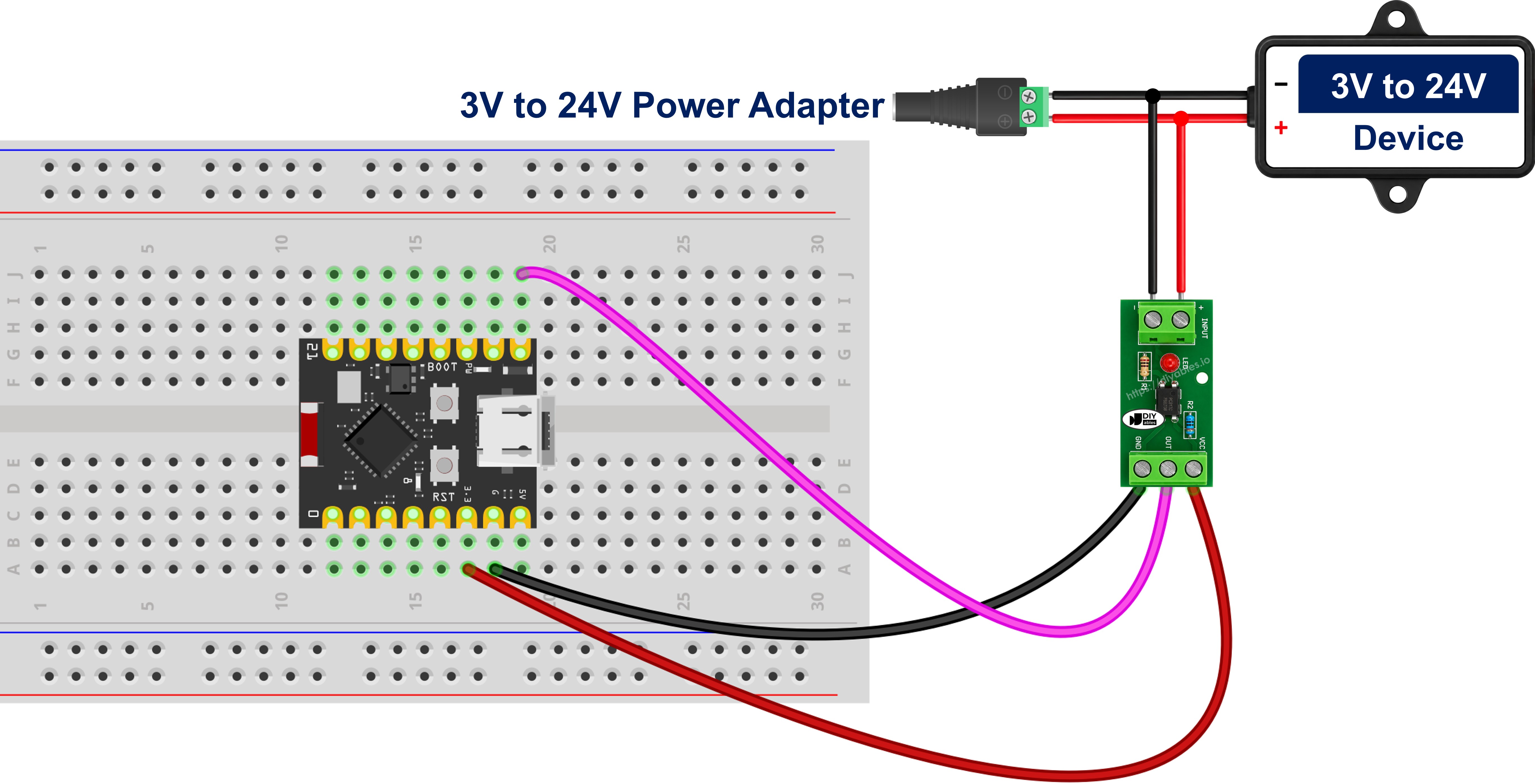
This image is created using Fritzing. Click to enlarge image
| Module Terminal/Pin | Connect To |
|---|---|
| IN+ (screw terminal) | the 12V/24V signal wire |
| IN- (screw terminal) | the ground of the 12V/24V circuit |
| VCC (header pin) | ESP32 C3 Super Mini 3.3V |
| GND (header pin) | ESP32 C3 Super Mini GND |
| OUT (header pin) | D5 |
- Power the output side from 3.3V, not from 5V - the ESP32 C3 Super Mini is not 5V tolerant, and the module's OUT pin swings to whatever you feed VCC
- No resistor of your own goes anywhere near IN+. The module already has one, and adding a second one in series only starves the LED
- The screw-terminal side and the header side are two separate circuits that share nothing but the insulating gap inside the PC817
- The input side is an LED and conducts one way only: IN+ takes the positive or switched wire, IN- the return
Optional - Building the Same Input From the Bare PC817 Chip
Prefer to solder your own? A bare PC817 is a 4-pin DIP with a dot or notch beside pin 1, and one resistor turns it into the same isolated input.
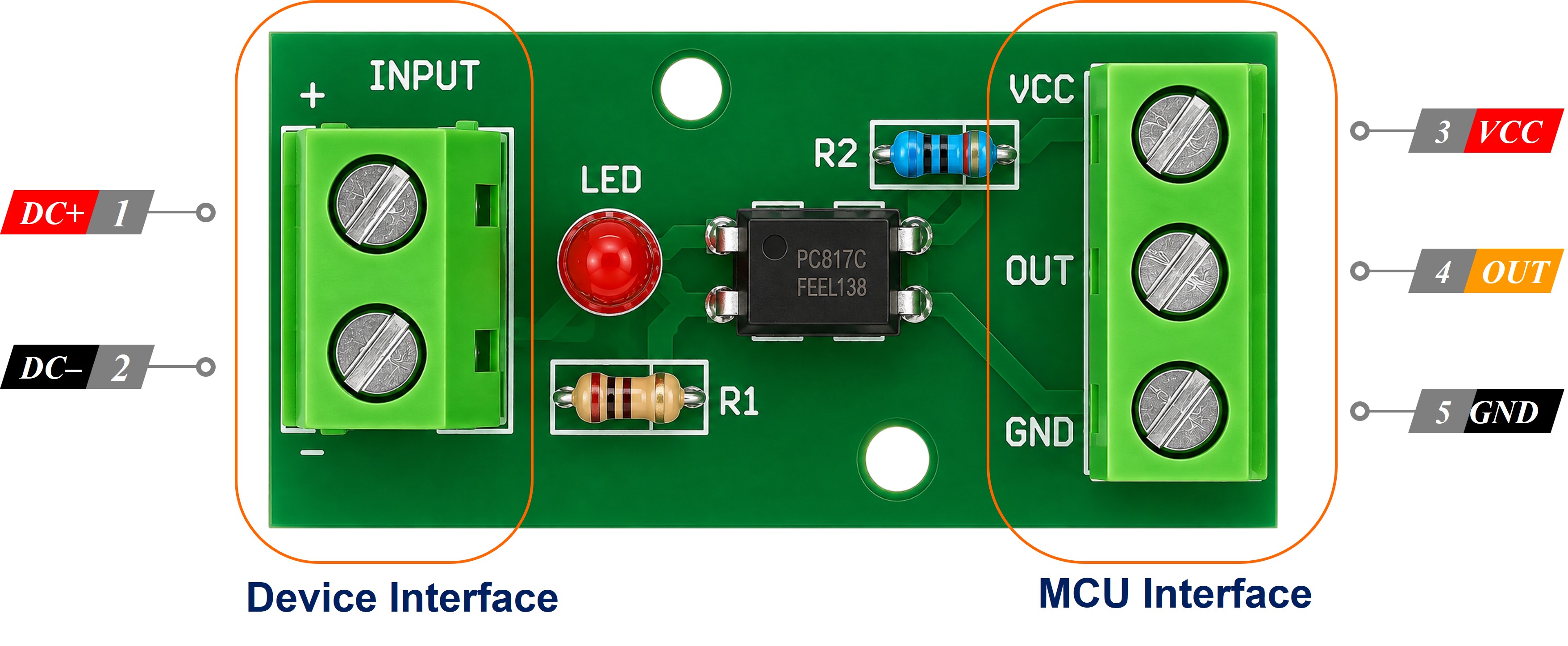
- Pin 1 - Anode (A): input side - the 12V/24V signal, through your series resistor
- Pin 2 - Cathode (K): input side - the ground of the 12V/24V circuit, never the board ground
- Pin 3 - Emitter (E): output side - ESP32 C3 Super Mini GND
- Pin 4 - Collector (C): output side - D5
Sizing that resistor is exactly the job the module's variant did for you. Aim for 10 mA through the internal LED: R = (Vin - 1.2) / 0.01.
| Input voltage | Resistor to fit | Note |
|---|---|---|
| 3.3V | 220 ohm | about 9.5 mA, 1/4 W |
| 5V | 390 ohm | about 9.7 mA, 1/4 W - 470 ohm is a fine stand-in |
| 12V | 1 kohm | about 10.8 mA, 1/4 W |
| 24V | 2.2 kohm | about 10.4 mA - use a 1/2 W resistor here |
Change the resistor whenever the input voltage changes: leave 1 kohm in place and feed it 24 volts and about 22.8 mA flows, past the LED's 20 mA limit.
Wiring the Module in Parallel With a Device That Is Already Installed
The best job for a board this cheap and this small is a retrofit: a 12V DC doorbell chime, an appliance or a pump that is already screwed to the wall and wired in, which you now want to watch without taking any of it apart. That works because the module's input goes across the device - in parallel with it. Nothing in the existing circuit is cut, unplugged or rerouted; you land two wires on terminals that are already there and leave everything else alone.
WARNING
Never put the module in series with the device. In series, the whole load current of that chime, lamp or pump runs through the optocoupler's internal LED, which is rated for 20 mA - the part is destroyed the instant the device switches on. The tap goes across the device, not in line with it.
| Existing 12V/24V Device | Module Terminal |
|---|---|
| Positive / switched terminal | IN+ |
| Negative / return terminal | IN- |
- No series resistor is needed on a module tap: two wires run from the device's own terminals straight onto IN+ and IN-, because the resistor that sets the LED current is already on the module - which is also why the variant has to match the voltage you measured on that device
- The tap draws about 10 mA, which is nothing beside what a chime coil, a lamp, a valve or a motor pulls, so the device carries on behaving exactly as it did before. It is a read-only measurement
- Polarity matters: the input side is an LED and conducts one way only. Swap IN+ and IN- and it will simply never turn on, so check with a multimeter which terminal of the tap is positive before you tighten anything down
- The reading follows the device's real state: because the tap sits across the device instead of across your own switch, it is true whenever the equipment is energised - including when somebody else's push button, timer or thermostat turns it on, and including when it fails to come on at all. That is what makes run-hour logging, idle-time counting and "did it actually start?" alerts possible
- One honest limitation: this tells you the device is energised, not that it is working - a seized pump or a chime with a burnt-out coil still draws power and will still read as ON
- DC only: the PC817 input is a single LED, so it responds to one polarity. If that doorbell runs from an AC transformer rather than a 12V DC supply, this is the wrong part - sensing AC needs an optocoupler whose input stage carries two back-to-back LEDs
WARNING
A chime coil, relay, solenoid, contactor or motor throws a large reverse-voltage spike back down the wires when it switches off, and the PC817's input LED is rated for only 6 V in reverse. Fit an ordinary diode in reverse-parallel directly across the module's input terminals - cathode to IN+, anode to IN- (on a bare chip, the same way across pins 1 and 2). In normal operation that diode is reverse-biased and does nothing whatsoever; on a spike it conducts and clamps the reverse voltage to well under a volt. A 1N4148 covers a small tap, a 1N4007 a heavier one.
Is Your Optocoupler Module Active High or Active Low?
Start from the bare chip, because that part is settled physics. The PC817's output side does not push a voltage out - its phototransistor simply connects the digital pin to GND when it is switched on, so the pin needs a pull-up to have any voltage at all when the transistor is off. The ESP32 C3 Super Mini has an internal pull-up built into every GPIO, which is exactly what we use here.
| External 12V/24V signal | PC817 LED | Phototransistor | ESP32 C3 Super Mini pin reads |
|---|---|---|---|
| Present | on | conducting | LOW |
| Absent | off | blocking | HIGH |
So on a bare chip, signal present reads LOW - always. A module is where it gets interesting: most makers wire the chip exactly as in the table above and their OUT pin is active-LOW too, but some add an inverting stage on the board, so OUT follows the input and goes HIGH while the line is energised. Both kinds are sold under the same "PC817 isolation module" name, so check yours instead of assuming.
The one-minute polarity test:
- Wire the module as in the wiring table above and upload the ESP32 C3 Super Mini sketch further down this page
- Open the Serial Monitor at 115200, leave IN+ and IN- unconnected, and note what the sketch reports - that is your idle state
- Now energise the input side. The module's own status LED should light: that LED is the honest witness here, because it sits on the isolated input side and cannot be fooled by anything happening in your code
- Whatever the sketch reports while that status LED is lit is the active state
- If the status LED is lit and the sketch still says the line is quiet, your module is the active-HIGH kind
Fixing it is one edit, not a rewrite: the sketch carries a single MODULE_ACTIVE_LOW constant near the top, set to true by default. Change it to false, upload again, and every message comes out the right way round. Nothing else in the code has to change.
※ NOTE THAT:
An external 10 kohm resistor from the digital pin to 3.3V works just as well as the internal pull-up, but on a board with as few free pins and as little space as the ESP32 C3 Super Mini, using INPUT_PULLUP saves you a component and a breadboard row.
How To Program the PC817 on ESP32 C3 Super Mini
No library is involved. This is plain digital input reading, in two steps.
Step 1 - Set the pin as an input with the internal pull-up:
Step 2 - Turn the raw reading into a true/false answer, using your module's polarity:
ESP32 C3 Super Mini Code - Monitoring Whether a 24V Device Is On or Off
What the code does:
- Sets D5 as an input with the ESP32 C3 Super Mini's internal pull-up switched on
- Reads the module's OUT pin and converts it through the MODULE_ACTIVE_LOW constant, so one edit covers either polarity
- Prints a line only when the external line changes state, so the Serial Monitor stays readable
- Numbers each activation of the external 12V/24V line
- Reports how many seconds the line stayed live each time it switches off
Detailed Instructions
- Check the module variant before anything else: it has to match the voltage you measured on the line - this is the step that damages parts when skipped
- New to this board? Work through Getting Started with ESP32 C3 Super Mini first
- Wire the output side: module GND to GND, VCC to 3.3V, OUT to D5
- Wire the input side separately: IN+ and IN- onto the device, and keep the 12V/24V ground off the board entirely
- Connect the board: plug the ESP32 C3 Super Mini into your computer with the USB Type-C cable
- Select the board and port: choose ESP32C3 Dev Module in Tools > Board, then pick the COM port
- Upload: copy the code above into Arduino IDE and click Upload
- Open the Serial Monitor and set the baud rate to 115200
- Switch the external line on and off and watch the messages appear
- Run the polarity test once: if the messages come out backwards, set MODULE_ACTIVE_LOW to false and upload again
- Pro Tip: if the Serial Monitor shows the line as live before you switch anything on, either your two grounds are tied together or your module is the active-HIGH kind
Serial Monitor Output
Note: with MODULE_ACTIVE_LOW left at true, the pin itself reads LOW on every line that says LIVE. The code has already converted it for you.
Line-by-line Code Explanation
The ESP32 C3 Super Mini code above contains a line-by-line explanation in its comments. Please read the comments in the code!
Application and Project Ideas
The ESP32 C3 Super Mini is cheap and physically tiny, which makes it the natural board to leave permanently inside equipment that already runs on 12V or 24V.
- Retrofit a 12V garage-door controller: tap the controller's 12V output through a 12V module and have the board push a WiFi notification whenever the door is driven, without modifying the controller itself
- Count the run hours of a 12V pump or fan: tap across the device itself, number every time it is energised and total how long it ran, so you can tell at a glance whether it started at all today
- Know when an existing doorbell chime actually rang: the 12V DC chime stays wired exactly as the installer left it, and the parallel tap turns each ring into a message from the board
- Watch a 24V machine fault lamp: wire a 24V module across the fault-lamp line in a control cabinet and log every time the machine faults, using the timestamps the code already collects
- Squeeze an isolated input into a sealed enclosure: a single-channel module and this board fit inside a small IP-rated box that a full-size development board would not, which suits outdoor 12V gate and pump installations
- Check whether a 12V vehicle circuit is live: monitor ignition, headlights or a door switch from inside a car without exposing the board to the vehicle's electrical system
- Sense a 24V solenoid or contactor coil being energised: confirm from software that the coil actually got its command, not just that you sent one
- Add a channel to something you already built: pair the isolated input with a relay so a 24V field signal switches a separate load
- Extend a long-run switch: on cables long enough that a plain button input picks up noise, run the loop at 24V and read it through a module instead
Video Tutorial
Watch the video below for a visual walkthrough of this project.
Challenge Yourself
Push your ESP32 C3 Super Mini PC817 optocoupler build a little further with these.
- Easy: Rewrite the printed labels for your own equipment - "ignition", "pump running", "gate opening" - instead of the generic 24V wording
- Easy: Mirror the isolated input onto the on-board LED on GPIO8, so you can see the state without a Serial Monitor
- Easy: Flip MODULE_ACTIVE_LOW to false on purpose, watch every message come out backwards, then set it back - you will recognise the symptom instantly if you ever meet a module wired the other way
- Medium: Keep a running total of how long the external line has been live since power-up, and print it once a minute
- Medium: Raise an alert when the 24V line stays live longer than a limit you choose - a stuck contactor or a jammed gate looks exactly like that
- Medium: Move the same sketch from a 24V module to a 12V one on different equipment, and confirm the code needs no change at all
- Advanced: Add software debouncing so a chattering 12V relay contact does not register as dozens of activations
- Advanced: Move up to a 4-channel module and watch four separate 24V machine signals at once, reporting the state of all four over WiFi
Troubleshooting
Every reading is exactly backwards (it says LIVE while the chime is silent, and quiet while the chime is ringing):
- Your module is the active-HIGH kind - some makers invert the output on the board. Run the one-minute polarity test above and compare the module's status LED against what the Serial Monitor prints
- Set MODULE_ACTIVE_LOW to false at the top of the sketch and upload again. That single constant is the whole fix
The pin always reads LOW (the code always says LIVE):
- The two grounds are joined somewhere - separate them
- On the bare chip, the PC817 is inserted backwards; find the dot or notch that marks pin 1
The pin always reads HIGH (nothing is ever detected):
- You are feeding a 24V module from a 12V line, so its LED is underdriven - fit the variant that matches the voltage you measured
- IN+ and IN- are swapped, so the internal LED is reverse-biased and never lights
- The external 12V/24V signal is not actually present - check it with a multimeter first
The reading never returns to inactive (it says LIVE even with the device switched off):
- The source is a solid-state output - a PLC transistor output, a triac output or an LED lamp driver - and those leak a small current even when off, which is enough to partly light the module's LED
- Fit a bleeder resistor of about 4.7 kohm to 10 kohm in parallel with the module's input terminals, so the leakage flows through the resistor instead of through the LED
- If the source is a plain mechanical contact, look for the two grounds being joined instead
The reading is unstable:
- INPUT_PULLUP is missing from pinMode(), leaving the pin floating
- The external contact is mechanical and chattering - add debouncing