
ESP32 C3 Super Mini - Potentiometer Servo Motor
Turn a knob and watch a servo motor follow it. In this beginner tutorial, the ESP32 C3 Super Mini reads a potentiometer and sets the servo motor angle from that reading. It is a simple first project that joins analog input with motor control.
In this tutorial, you'll learn:
- How to connect a potentiometer and a servo motor to the ESP32 C3 Super Mini
- How to program the ESP32 C3 Super Mini to read the potentiometer value
- How to convert that value (0 to 4095) into an angle (0° to 180°)
- How to control the servo motor based on the potentiometer position
- How to check the values in the Serial Monitor
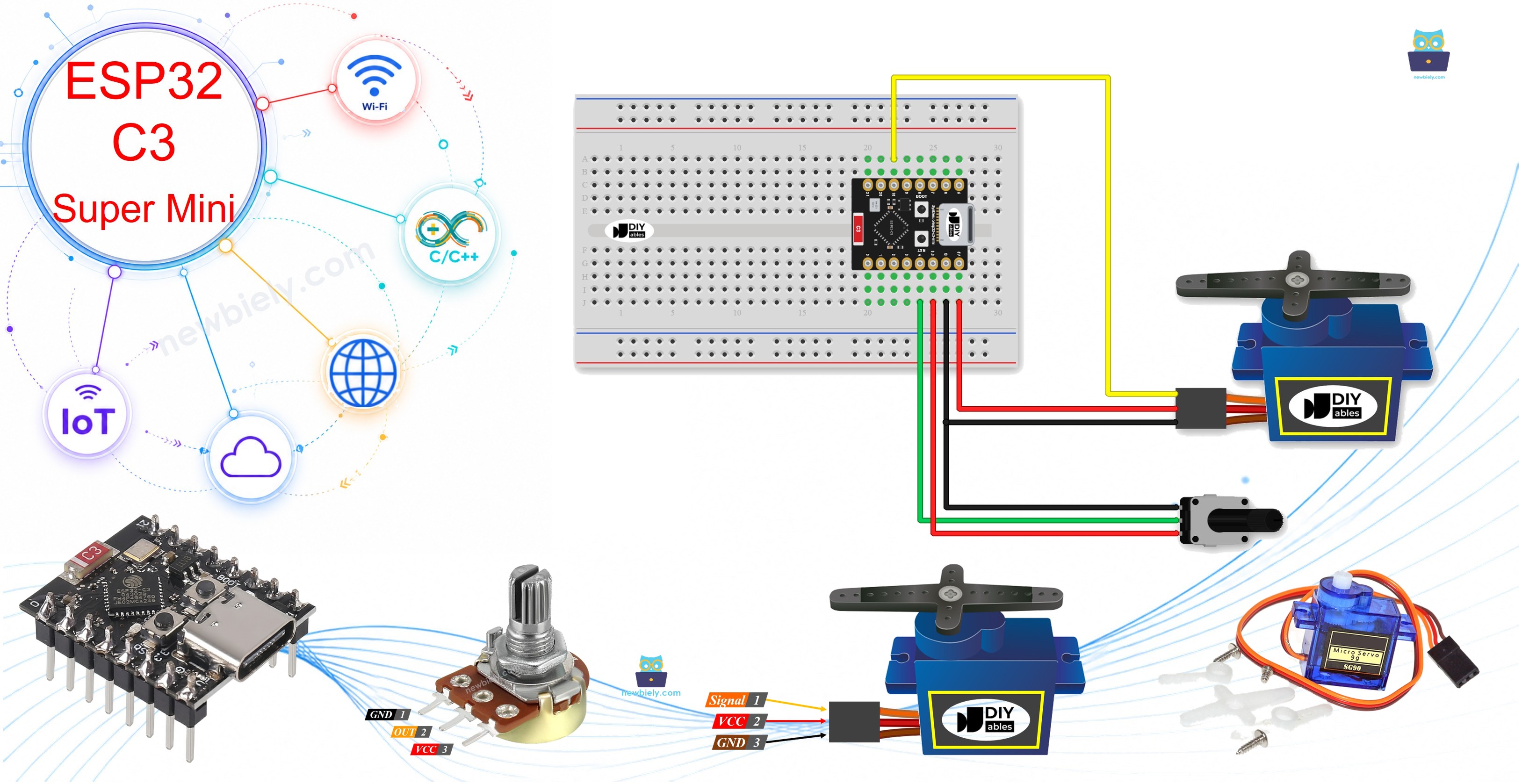
Hardware Preparation
Or you can buy the following kits:
| 1 | × | DIYables Sensor Kit (18 sensors/displays) |
Additionally, some of these links are for products from our own brand, DIYables .
Buy Note: For controlling multiple servo motors, use the PCA9685 16 Channel PWM Servo Driver Module to save MCU pins and simplify wiring.
Overview of Servo Motor and Potentiometer
A servo motor is an actuator that turns to an exact angle, and a potentiometer is a knob that gives a changing analog voltage.
Key Features:
- Potentiometer: gives the input value when you turn the knob.
- Servo motor: moves to the angle set by your code.
- Together: the knob position sets the servo position.
Technical Specifications:
- Servo motor angle: 0° to 180°
- ADC reading on this board: 0 to 4095 (12-bit)
- Potentiometer voltage on the signal pin: 0V to 3.3V
New to these parts? These tutorials explain the pinout, how they work, and how to program them:
Pinout
Each part has three pins.
Servo motor:
- VCC pin: (red) connect to 5V.
- GND pin: (brown or black) connect to GND.
- Signal pin: (yellow or orange) receives the control signal from the board.
Potentiometer:
- VCC pin: connect to 3.3V.
- GND pin: connect to GND.
- Output pin: sends the analog voltage to the board.
Wiring Diagram
Connect both parts to the ESP32 C3 Super Mini as shown below.
- Note: Power the potentiometer from 3.3V, never 5V. More than 3.3V on a GPIO pin can damage the board.
- Note: The potentiometer output must go to one of GPIO0 to GPIO4. Other pins cannot do an analog reading on this board.
- Note: The 5V pin is fine for one small servo motor. Use an external power supply for a bigger servo motor.
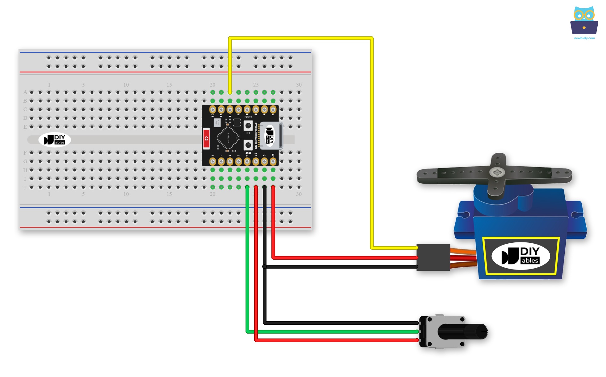
This image is created using Fritzing. Click to enlarge image
Here is the same wiring without a breadboard:
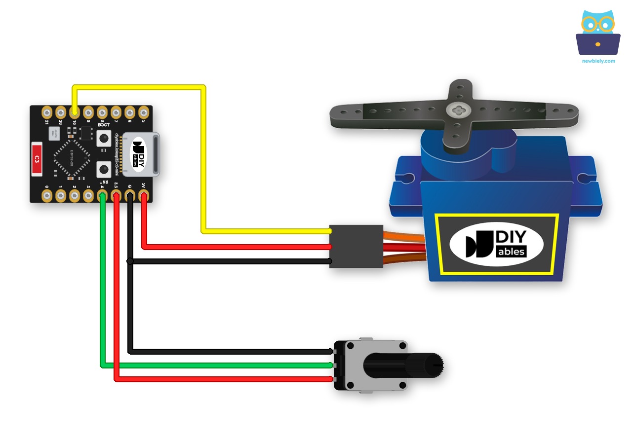
This image is created using Fritzing. Click to enlarge image
| Potentiometer Pin | ESP32 C3 Super Mini Pin |
|---|---|
| VCC | 3.3V |
| GND | GND |
| Output | GPIO4 |
| Servo Motor Pin | ESP32 C3 Super Mini Pin |
|---|---|
| VCC (Red) | 5V |
| GND (Brown/Black) | GND |
| Signal (Yellow/Orange) | GPIO10 |
How To Program
The program needs only three simple actions.
- Read the potentiometer: the value ranges from 0 to 4095.
- Convert it to an angle: the angle ranges from 0 to 180.
- Control the servo motor: move it to that angle.
ESP32 C3 Super Mini Code
This code moves the servo motor on GPIO10 according to the potentiometer on GPIO4.
What This Code Does:
- Starts Serial: opens the Serial Monitor at 115200 baud.
- Sets the ADC: analogSetAttenuation(ADC_11db) lets the pin read the full 0V to 3.3V range.
- Reads the knob: analogRead() gives a number from 0 to 4095.
- Sets the angle: map() converts that number to 0° to 180° and servo.write() moves the servo motor.
- Prints the values: shows the reading and the angle every 100 ms.
Detailed Instructions
- New to ESP32 C3 Super Mini? Complete our Getting Started with ESP32 C3 Super Mini tutorial first to set up your development environment.
- Wire it up: Connect the parts as shown in the wiring diagram above.
- Connect the board: Plug the ESP32 C3 Super Mini into your computer with a USB Type-C cable.
- Open the IDE: Open Arduino IDE on your computer.
- Select the board: Make sure ESP32 C3 Super Mini is selected in Tools > Board.
- Select the port: Pick the COM port of your board in Tools > Port.
- Install the library: Click the Libraries icon on the left bar, search for "ESP32Servo", and install the library by Kevin Harrington and John K. Bennett.
- Search for ESP32Servo created by Kevin Harrington,John K. Bennett and click the Install button.
- Copy the code: Copy the code above and paste it into Arduino IDE.
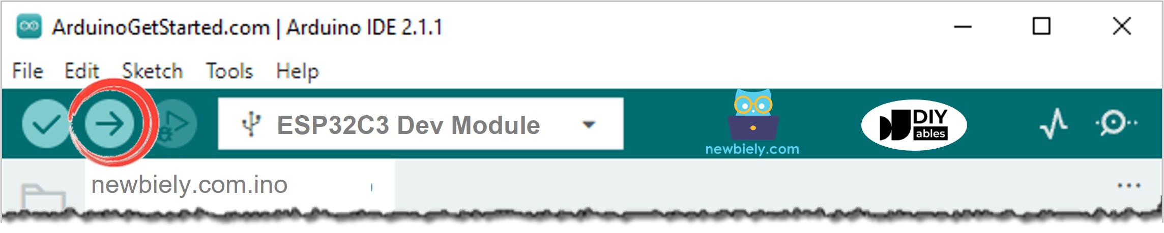
- Upload: Click the Upload button to send the code to the ESP32 C3 Super Mini.
- Open Serial Monitor: Set the baud rate to 115200.
- Turn the knob: Rotate the potentiometer slowly from one end to the other.
- Watch the servo motor: It rotates as you turn the knob.
- Check the result: The Serial Monitor shows the values. It looks like the below:
- Pro Tip: If the servo motor shakes or the board restarts, the servo motor may need more current. Try an external power supply and connect its GND to the board's GND.
Code Explanation
Check out the line-by-line explanation in the comments of the source code!
Project Ideas
You can use this knob and servo motor pair in many small builds.
- Camera Pan Control: Turn a knob to point a small camera left or right.
- Robot Arm Joint: Move one joint of a small arm by hand.
- Mini Gate: Open and close a model gate or door.
- Air Vent Flap: Set how far a small flap opens.
- Pointer Gauge: Use the servo motor as a needle that shows the knob position.
Challenge Yourself
Try these small upgrades to your ESP32 C3 Super Mini potentiometer servo motor project.
- Easy: Limit the movement to 45° to 135° by changing the map() values.
- Easy: Reverse the direction, so turning the knob right moves the servo motor left.
- Medium: Average 10 readings to make the servo motor move more smoothly.
- Medium: Show the angle on an LCD or OLED display.
- Advanced: Add a button on GPIO7 that saves the current angle and returns to it when pressed again.