
ESP32 C3 Super Mini - Keypad - LCD
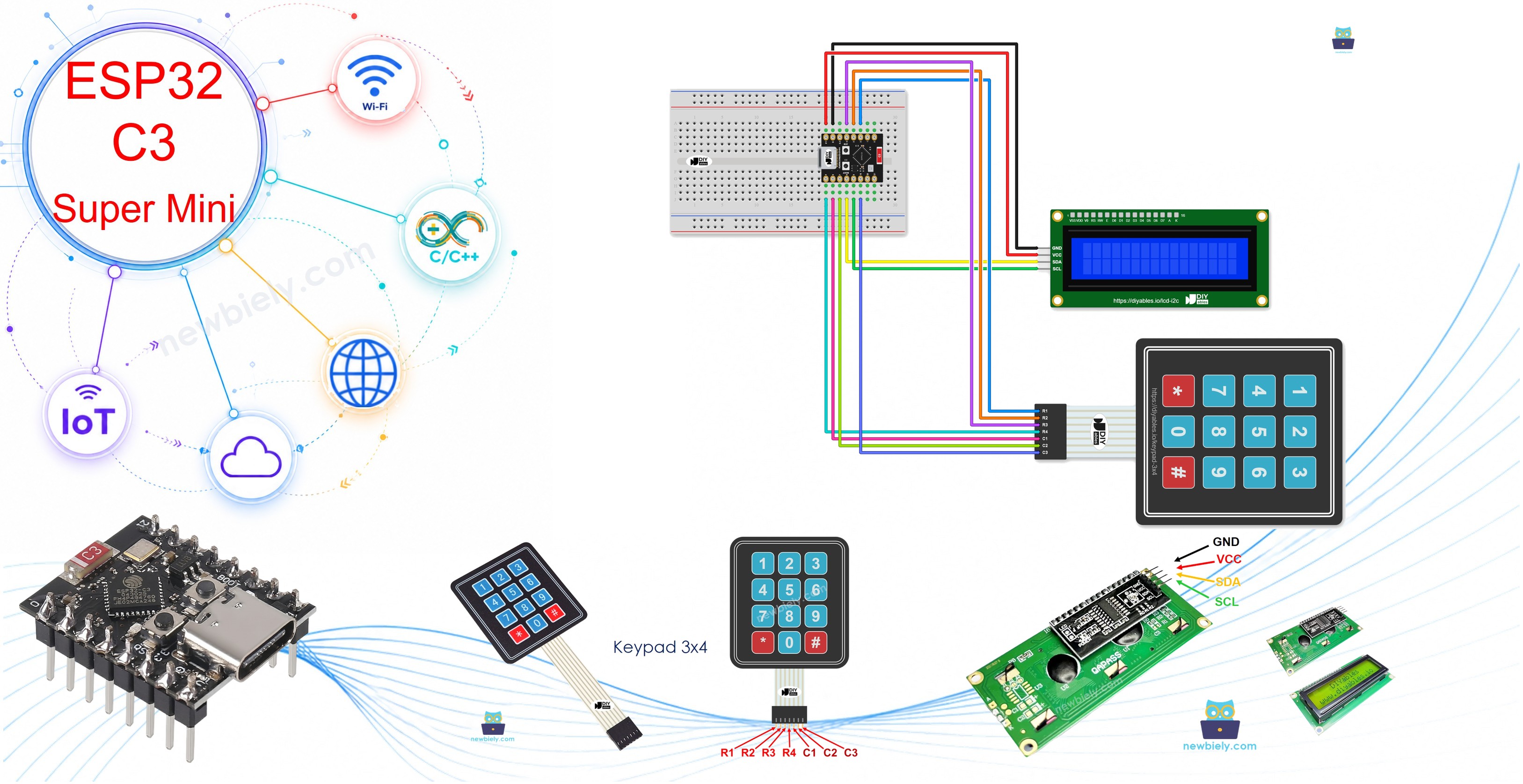
This tutorial shows you how to use the ESP32 C3 Super Mini with a keypad and an LCD display. You will program the board to show each pressed key on the LCD, with no computer needed to read the result. This ESP32 C3 Super Mini keypad LCD project is a great base for a door lock or a menu.
In this tutorial, you'll learn:
- How to connect a keypad and an LCD I2C to the ESP32 C3 Super Mini
- How to read the pressed key from a 3x4 keypad
- How to show the pressed key on the LCD
- How to combine keypad code and LCD code
- How to upload and test the project step by step
Hardware Preparation
Or you can buy the following kits:
| 1 | × | DIYables Sensor Kit (18 sensors/displays) |
Additionally, some of these links are for products from our own brand, DIYables .
Buy Note: Most LCD I2C displays available on the market are 5V displays. They may work with this board, but it is unsafe and can damage the board. We strongly recommend using the 3.3V LCD I2C display recommended above.
Overview of Keypad and LCD
The keypad is an input pad that sends the pressed key to the board, and the LCD I2C is a display that shows text using only two data wires.
Key Features:
- Keypad: Gives you 12 keys: 0-9, star and hash
- LCD I2C: Shows 2 rows of text with 16 characters in each row
- No keypad power: The keypad needs no VCC and no GND wire
Technical Specifications:
- Keypad layout: 4 rows x 3 columns
- Keypad pins: 7 pins (R1, R2, R3, R4, C1, C2, C3)
- LCD I2C power: 5V
- LCD I2C address: Usually 0x27 or 0x3F, depending on the manufacturer
We have a full tutorial for each part, with the pinout, how it works, wiring and code:
Pinout
The two parts have 11 pins in total.
Keypad 3x4:
- R1: Row 1, the top row of keys (1, 2, 3)
- R2: Row 2, the second row of keys (4, 5, 6)
- R3: Row 3, the third row of keys (7, 8, 9)
- R4: Row 4, the bottom row of keys (*, 0, #)
- C1: Column 1, the left column (1, 4, 7, *)
- C2: Column 2, the middle column (2, 5, 8, 0)
- C3: Column 3, the right column (3, 6, 9, #)
LCD I2C:
- VCC: Connect to 5V power
- GND: Connect to ground (0V)
- SDA: I2C data signal
- SCL: I2C clock signal
Wiring Diagram
Connect both parts to the ESP32 C3 Super Mini as shown below.
- Note: Unplug the USB cable before you change any wire.
- Note: The LCD uses the 5V pin for power. The keypad has no power wire.
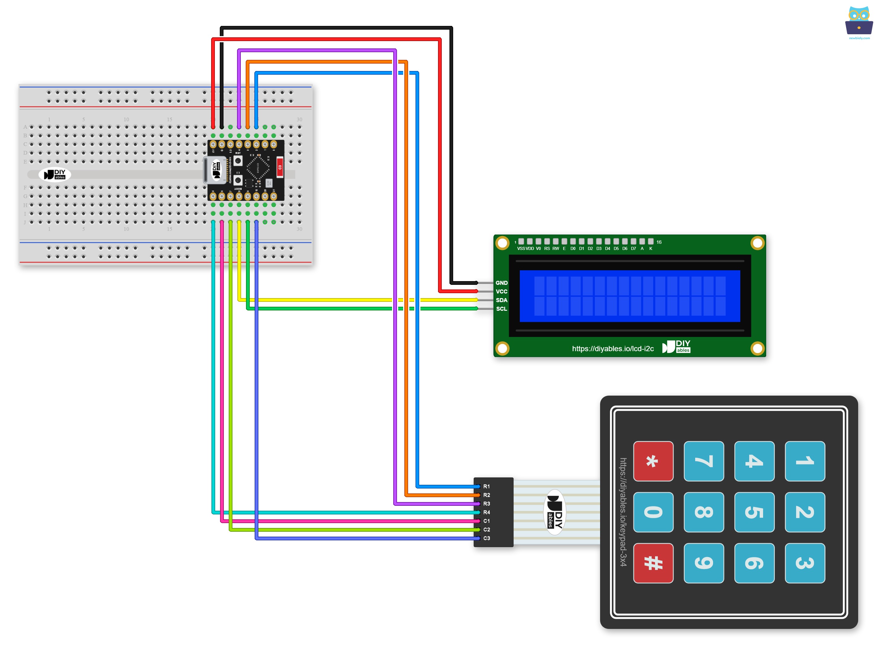
This image is created using Fritzing. Click to enlarge image
No breadboard? The same circuit can be wired without one, as shown below:
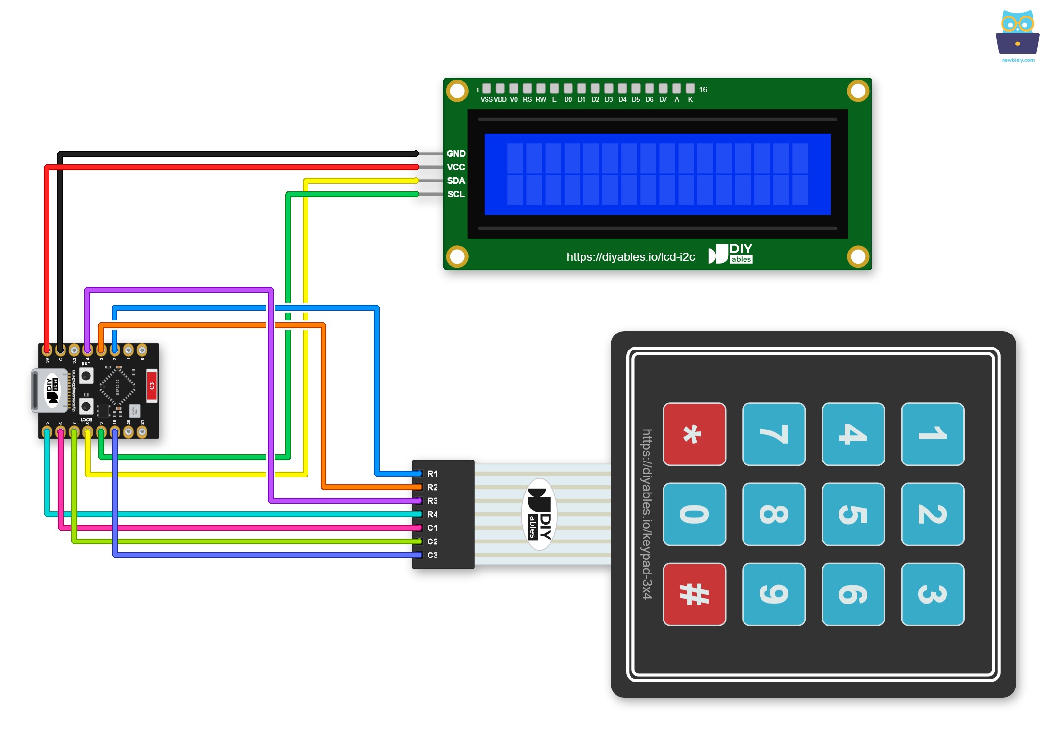
This image is created using Fritzing. Click to enlarge image
| Keypad Pin | ESP32 C3 Super Mini Pin |
|---|---|
| R1 | GPIO2 |
| R2 | GPIO3 |
| R3 | GPIO4 |
| R4 | GPIO5 |
| C1 | GPIO6 |
| C2 | GPIO7 |
| C3 | GPIO10 |
| LCD I2C Pin | ESP32 C3 Super Mini Pin |
|---|---|
| VCC | 5V |
| GND | GND |
| SDA | GPIO8 |
| SCL | GPIO9 |
ESP32 C3 Super Mini Code - Keypad 3x4 - LCD I2C
The code below reads the keypad and shows each pressed key on the LCD.
What This Code Does:
- Uses I2C: The LCD uses the default I2C pins of the board: GPIO8 (SDA) and GPIO9 (SCL)
- Starts the LCD: Turns on the LCD and its backlight
- Reads the keypad: Checks for a pressed key again and again
- Shows the key: Prints each key on the first row, one position after the other
- Starts over: Clears the LCD when the cursor reaches position 16
※ NOTE THAT:
The LCD I2C address can be different from each manufacturer. In the code, we used address of 0x27 that is specified by DIYables manufacturer
Detailed Instructions
Follow these bullets to run the project.
- New to ESP32 C3 Super Mini? Complete our Getting Started with ESP32 C3 Super Mini tutorial first to set up your development environment.
- Wire the parts: Connect the parts as shown in the wiring diagram.
- Connect your board: Plug the ESP32 C3 Super Mini into your computer with a USB Type-C cable.
- Open the IDE: Launch the Arduino IDE on your computer.
- Select your board: Make sure ESP32 C3 Super Mini is selected in Tools > Board.
- Select your port: Choose the matching COM port.
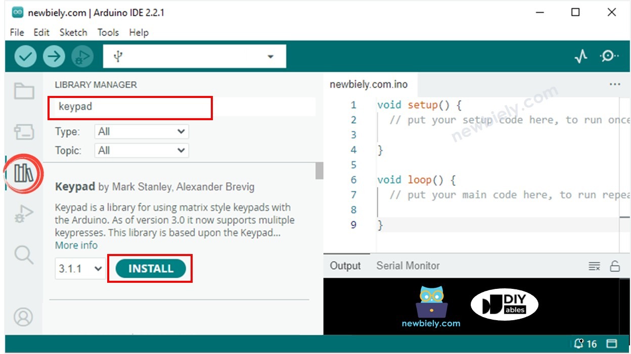
- Open the Library Manager: Click the Libraries icon on the left bar of the Arduino IDE.
- Search for the keypad library: Type “keypad” in the search box, then look for the keypad library by Mark Stanley, Alexander Brevig.
- Install the keypad library: Click the Install button.
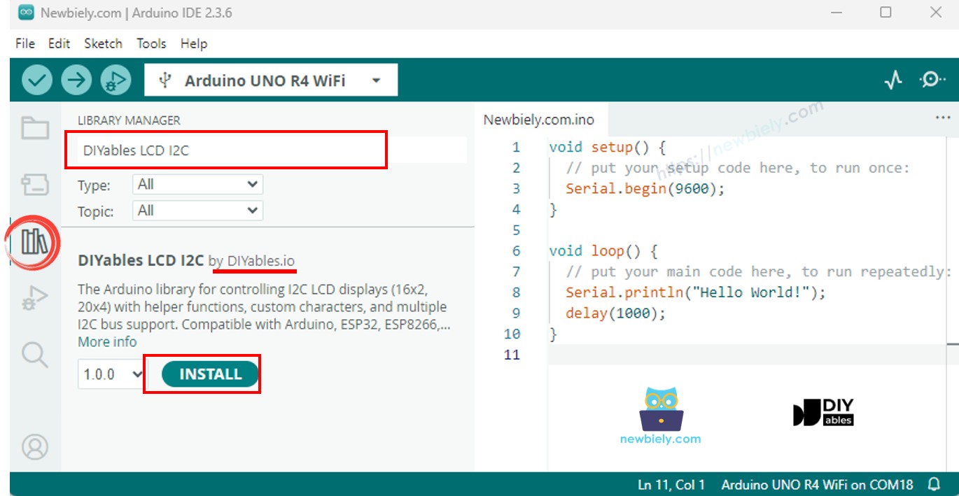
- Search for the LCD library: Type “DIYables LCD I2C” in the search box, then look for the DIYables_LCD_I2C library by DIYables.
- Install the LCD library: Click the Install button.
- Copy the code: Copy the code above and paste it into the Arduino IDE.
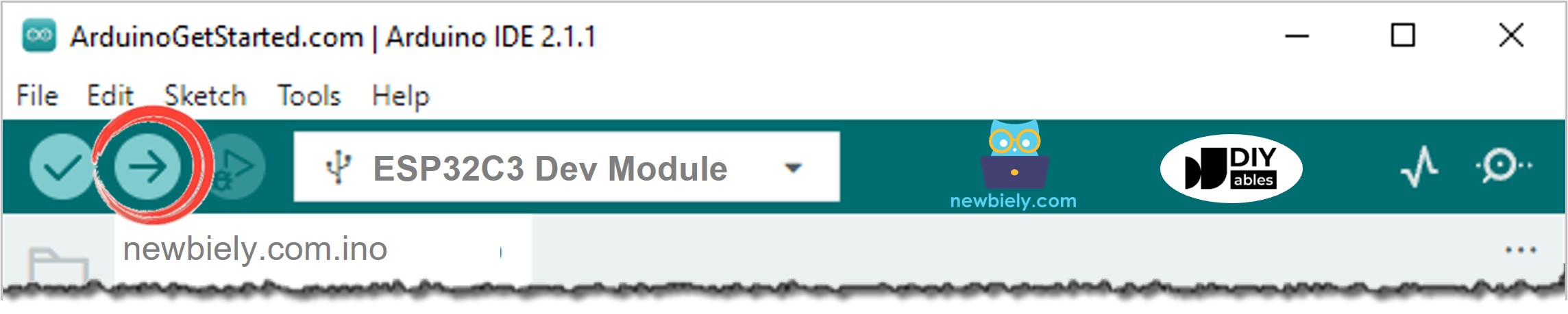
- Upload the code: Click the Upload button to compile and upload the code to your ESP32 C3 Super Mini.
- Test it: Press some keys on the keypad.
- See the result: Watch the keys appear on the LCD.
- Pro Tip: If the LCD backlight is on but you see no text, turn the small contrast screw on the back of the LCD.
If the LCD does not display anything, see Troubleshooting on LCD I2C
Line-by-line Code Explanation
The above ESP32 C3 Super Mini code contains line-by-line explanation. Please read the comments in the code!
Application and Project Ideas
You can use this ESP32 C3 Super Mini keypad LCD project as the base for many useful builds.
- Door lock panel: Type a PIN code and see each digit on the LCD
- Simple calculator: Type numbers and show the result on the LCD
- Menu system: Pick a setting with the keys and show it on the LCD
- Timer setter: Type a time in seconds and show the countdown
- Quiz box: Let players type an answer and show the score
Challenge Yourself
Ready to do more with your ESP32 C3 Super Mini, keypad and LCD? Try these challenges.
- Easy: Show a welcome message on the LCD when the board starts
- Easy: Clear the LCD when the * key is pressed
- Medium: Use the second row when the first row is full
- Medium: Show a star on the LCD instead of the real key, to hide a password
- Advanced: Check a password and show "Correct" or "Wrong" on the LCD
- Advanced: Add a relay that opens a door lock when the password is correct