
ESP32 C3 Super Mini - Motion Sensor - Relay
This ESP32 C3 Super Mini motion sensor relay tutorial shows you how to switch a device on automatically when someone moves nearby. The ESP32 C3 Super Mini turns the relay on when the HC-SR501 detects motion, and turns it off when the motion stops.
In this tutorial, you'll learn:
- How to wire an HC-SR501 motion sensor and a relay to ESP32 C3 Super Mini
- How to set the sensor adjusters before you start
- How to program ESP32 C3 Super Mini to control a relay from motion
- How to read motion events in the Serial Monitor
- How to extend the project to a LED strip, siren, light bulb or actuator
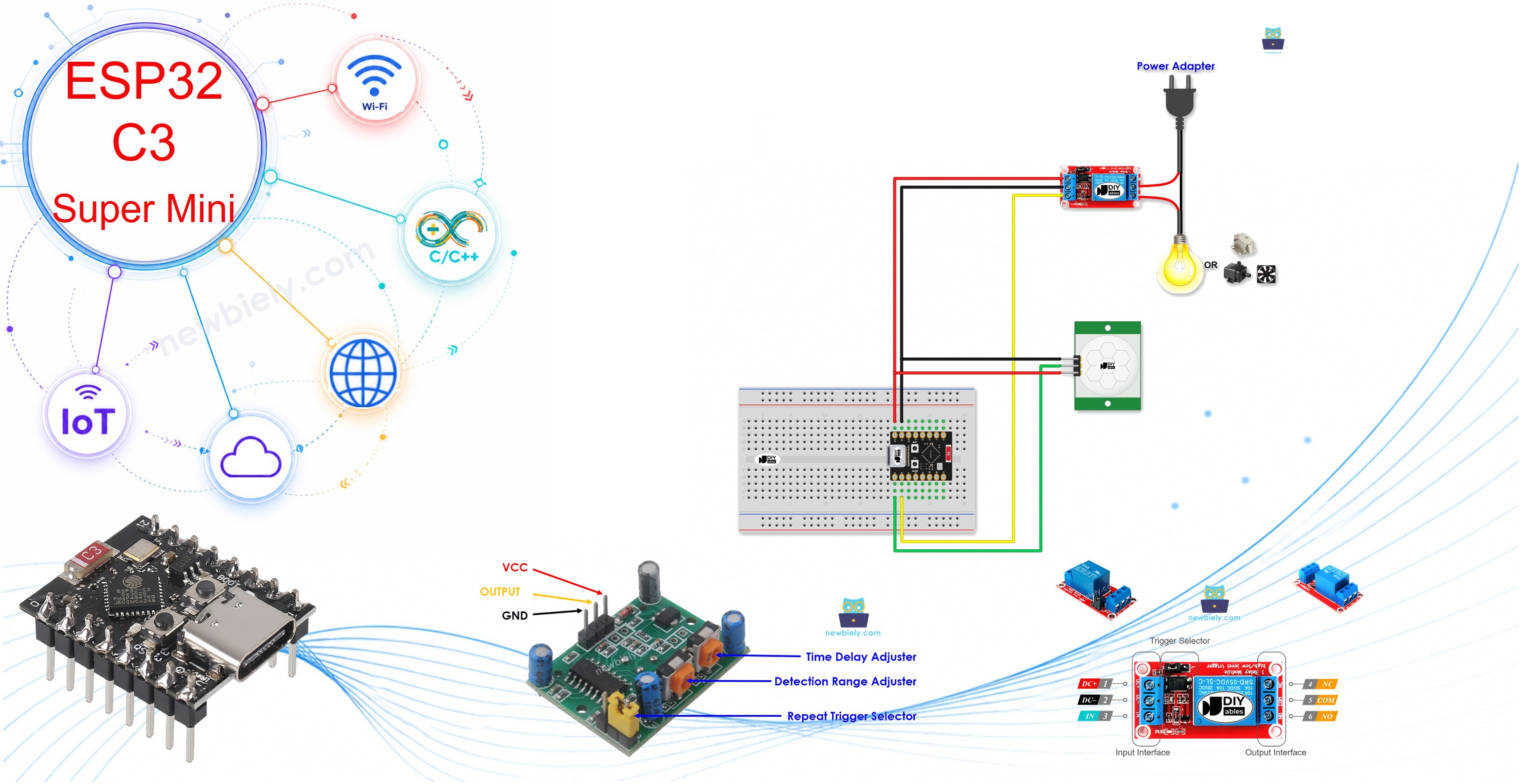
Hardware Preparation
Or you can buy the following kits:
| 1 | × | DIYables Sensor Kit (18 sensors/displays) |
Additionally, some of these links are for products from our own brand, DIYables .
Overview of Relay and Motion Sensor
A relay is a switch your code can control, and the HC-SR501 is a sensor that detects moving people and animals.
- Relay: Switches a higher-power device on and off from one output pin
- HC-SR501 Motion Sensor: Sends HIGH when it detects motion and LOW when it does not
- Relay guide: See the ESP32 C3 Super Mini - Relay tutorial for the pinout, how it works and more
- Motion sensor guide: See the ESP32 C3 Super Mini - Motion Sensor tutorial for the pinout, how it works and more
Wiring Diagram
Connect the motion sensor and the relay to your ESP32 C3 Super Mini as shown below.
- Note: Both the HC-SR501 and the relay use the 5V pin for power
- Note: The OUTPUT pin of the HC-SR501 gives about 3.3V, so it is safe for GPIO5
- Note: Turn off all power before you change any wire
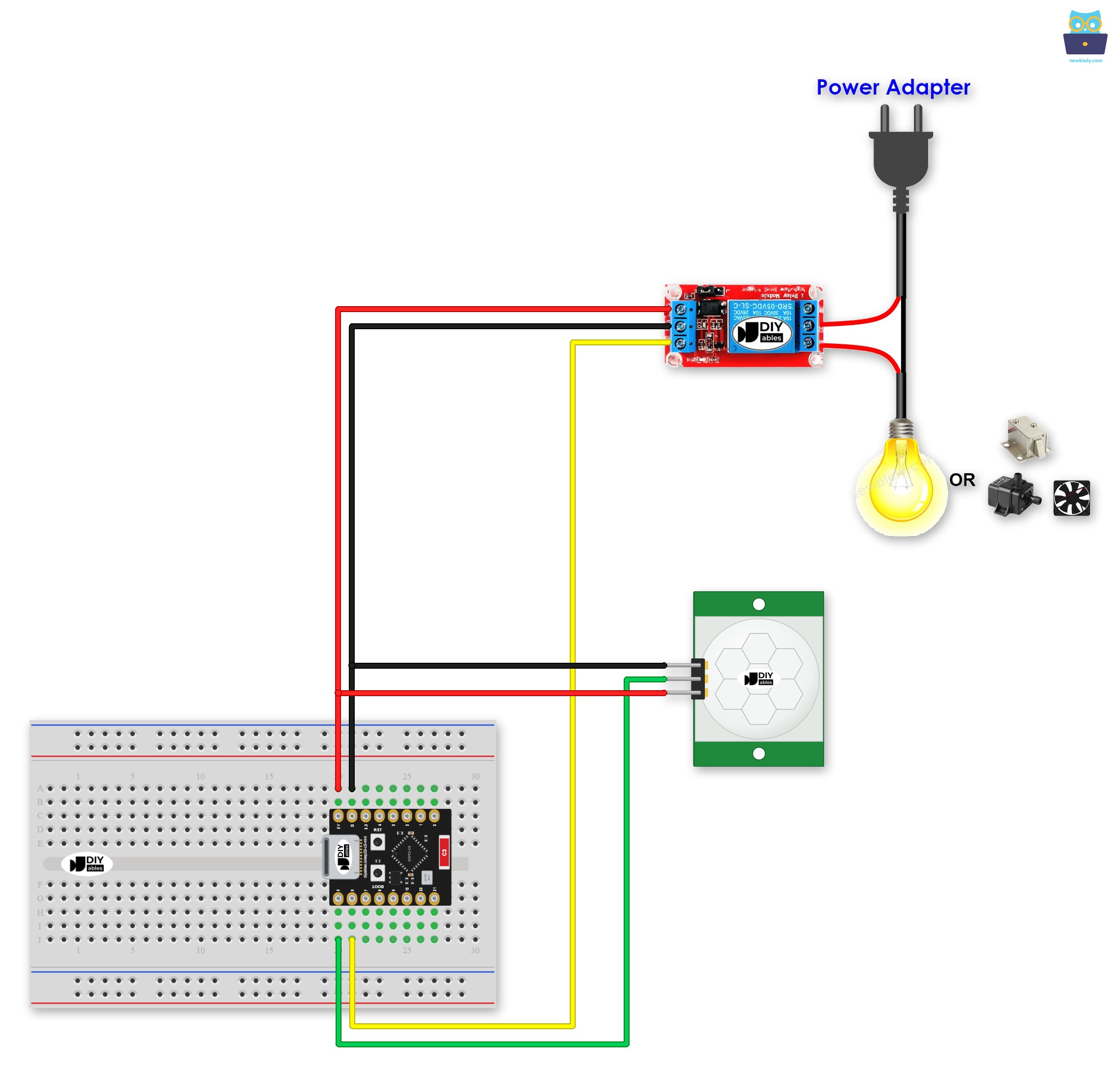
This image is created using Fritzing. Click to enlarge image
| HC-SR501 Pin | ESP32 C3 Super Mini Pin |
|---|---|
| VCC | 5V |
| GND | GND |
| OUTPUT | GPIO5 |
| Relay Pin | ESP32 C3 Super Mini Pin |
|---|---|
| DC+ | 5V |
| DC- | GND |
| IN | GPIO6 |
Initial Setting
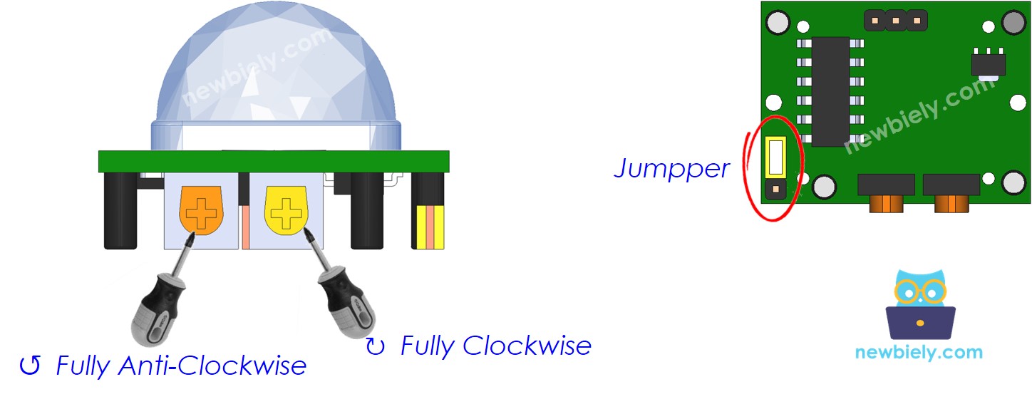
Set the HC-SR501 adjusters before you run the code.
| Setting | Configuration |
|---|---|
| Detection Range Adjuster | Fully screw it in the clockwise direction. |
| Time Delay Adjuster | Fully screw it in the anti-clockwise direction. |
| Repeat Trigger Selector | Put jumper like the below image. |
ESP32 C3 Super Mini Code
This code turns the relay on and off based on the motion sensor.
What This Code Does:
- Reads the HC-SR501 motion sensor on GPIO5
- Detects when motion starts (LOW to HIGH)
- Turns the relay on with GPIO6 when motion starts
- Detects when motion stops (HIGH to LOW)
- Turns the relay off and prints each event to the Serial Monitor
Detailed Instructions
- New to ESP32 C3 Super Mini? Complete our Getting Started with ESP32 C3 Super Mini tutorial first to set up your development environment.
- Wire It Up: Do the wiring as shown in the image above.
- Connect the Board: Connect the ESP32 C3 Super Mini to your PC with a USB Type-C cable.
- Open the IDE: Open Arduino IDE on your PC.
- Select the Board: Make sure ESP32 C3 Super Mini is selected in Tools > Board.
- Select the Port: Choose the right COM port in Tools > Port.
- Paste the Code: Copy the code above and paste it into Arduino IDE.
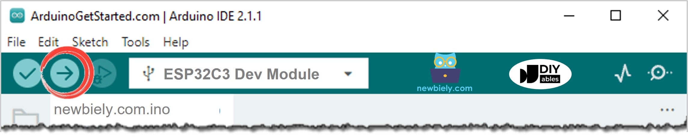
- Upload: Click the Upload button on Arduino IDE to compile and upload the code.
- Open Serial Monitor: Set the baud rate to 115200.
- Test It: Move your hand in front of the sensor.
- Check the Result: See the relay change state and read the message in the Serial Monitor.
- Pro Tip: If the Serial Monitor stays empty, set Tools > USB CDC On Boot to Enabled and upload again.
Line-by-line Code Explanation
The ESP32 C3 Super Mini code above has a comment on each important line.
- Read the comments: They explain what each line does, line by line.
Serial Monitor Output
When you move in front of the sensor and then stop, you will see this:
Relay vs MOSFET Module
A relay is not the only way to switch a device. If your device runs on DC power, such as a 12V LED strip, a 12V solenoid lock or a 12V fan, a MOSFET module can do the same job.
| Relay | MOSFET Module | |
|---|---|---|
| What it can do | turn the device on or off | turn the device on or off, and set its power (PWM) |
| Noise when switching | a click every time | no sound |
| How fast it switches | slow, a few milliseconds | very fast |
| Life | the contacts wear out after many switches | nothing moves, so it lasts long |
| Type of power | AC or DC | DC only |
| Device power supply | any voltage the relay is rated for | about 6V or more |
| Isolation from the ESP32 C3 Super Mini | yes, between coil and contacts | yes, by the PC817 optocoupler |
| Good for | AC devices, or a simple ON/OFF | DC devices, or dimming and speed control |
Both the relay and the MOSFET module turn on when the ESP32 C3 Super Mini pin is HIGH. The pin gives only 3.3V, but that is enough: the LED of the optocoupler on the module needs just a few milliamps. So for a simple ON/OFF, the code above stays the same and only the wiring changes.
- AC mains devices: Always use the relay.
- Learn more: See the ESP32 C3 Super Mini - MOSFET Module tutorial for the pinout, wiring, PWM code and safety tips.
Project Ideas
You can connect many devices to this ESP32 C3 Super Mini motion sensor relay project.
- Automatic Light: Turn on a LED strip or light bulb when someone walks in
- Intruder Siren: Sound a 12V buzzer or siren when motion is detected
- Warning Light: Flash a bright warning light near a door or gate
- Smart Fan: Run a 12V cooling fan only when someone is in the room
- Automatic Lock: Trigger a solenoid lock when someone comes close
- Moving Display: Start an actuator when a visitor walks past
Challenge Yourself
Try these ideas to grow your ESP32 C3 Super Mini skills.
- Easy: Change the Serial Monitor messages to your own text
- Easy: Add an LED on GPIO3 that follows the relay state
- Medium: Keep the relay on for 30 seconds after the motion stops
- Medium: Count how many times motion is detected and print the number
- Advanced: Add a button that turns the motion control on and off
- Advanced: Replace the relay with a MOSFET module and fade the device on with PWM