Arduino UNO R4 - TCS3200D/TCS230 Color Sensor
This guide will show you how to use Arduino UNO R4 and the TCS3200D/TCS230 color recognition sensor module to calibrate and read RGB values from objects and detect colors.
- How to connect the TCS3200D/TCS230 color sensor to Arduino UNO R4
- How to calibrate the sensor for your environment
- How to write a code for Arduino UNO R4 to read RGB values from the sensor
Hardware Preparation
Or you can buy the following kits:
| 1 | × | DIYables STEM V4 IoT Starter Kit (Arduino included) | |
| 1 | × | DIYables Sensor Kit (18 sensors/displays) |
Additionally, some of these links are for products from our own brand, DIYables .

Overview of TCS3200D/TCS230 Color Sensor
The TCS3200D/TCS230 is a color recognition sensor module that uses an 8x8 array of photodiodes. Sixteen photodiodes have red filters, 16 have green filters, 16 have blue filters, and 16 are clear (no filter). The module converts light intensity into a square-wave frequency signal. By switching the color filters and measuring the output frequency (or pulse width), we can estimate the RGB values of an object.
Many modules include white LEDs to illuminate the target. This makes the readings more consistent and helps the sensor detect colors reliably, even in low light.
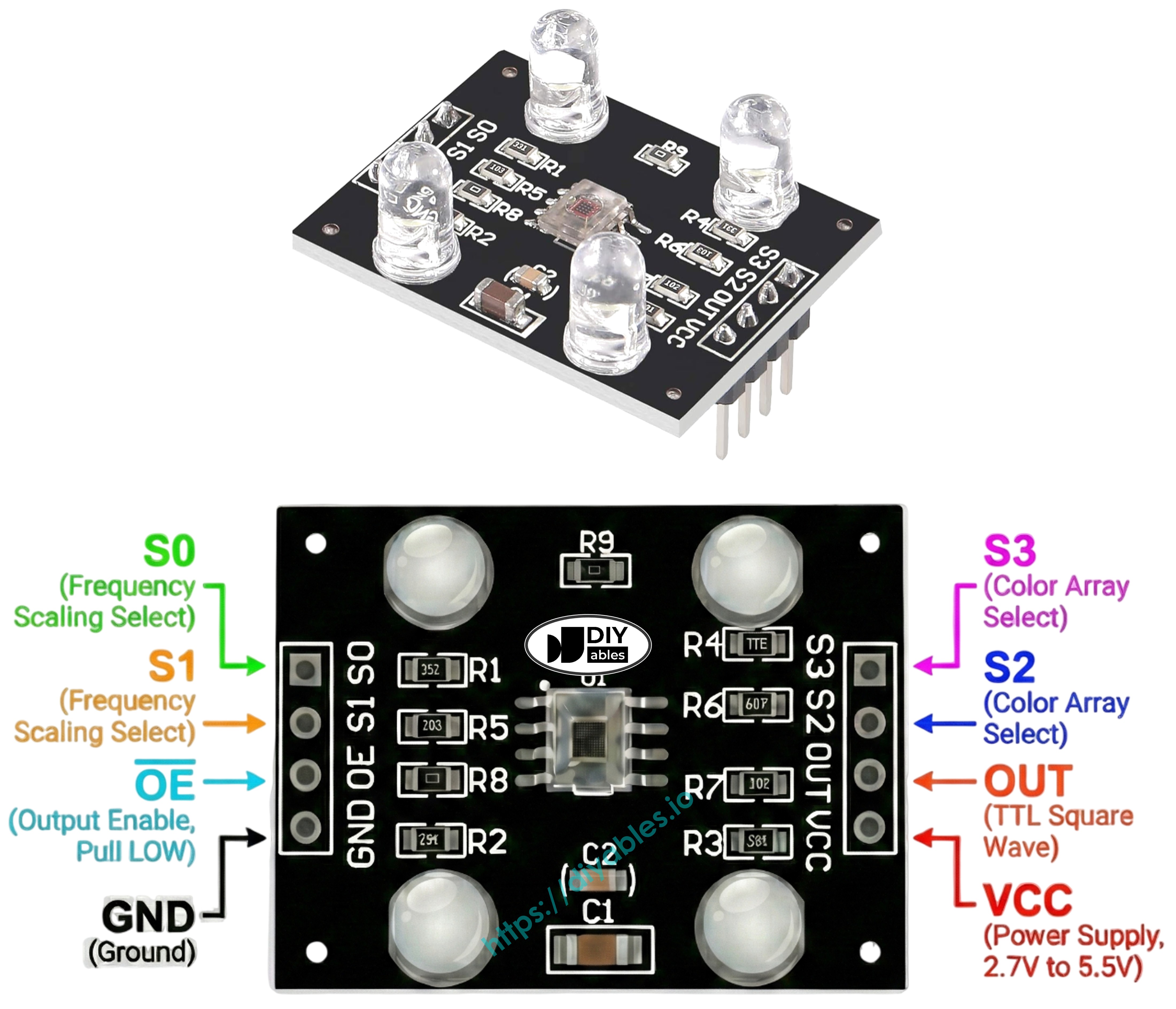
Pinout
The TCS3200D/TCS230 color sensor module typically has these pins:
- VCC pin: Connect this pin to VCC (5V).
- GND pin: Connect this pin to GND (0V).
- S0, S1 pins: Output frequency scaling selection.
- S2, S3 pins: Color filter selection.
- OUT pin: Square-wave frequency output.
- OE pin: Output enable (active LOW). Most modules already connect this pin to GND internally, so you do not need to wire it. If yours does not, connect it to GND.
How It Works
The sensor needs to be told two things: which color channel to measure, and how strong to make the output signal. Two pairs of control pins handle this:
- S0 and S1 control the output frequency scaling:
- S0 = LOW, S1 = LOW: Power down
- S0 = LOW, S1 = HIGH: 2% scaling
- S0 = HIGH, S1 = LOW: 20% scaling
- S0 = HIGH, S1 = HIGH: 100% scaling
- S2 and S3 select the color filter:
- S2 = LOW, S3 = LOW: Red filter
- S2 = LOW, S3 = HIGH: Blue filter
- S2 = HIGH, S3 = LOW: Clear (no filter)
- S2 = HIGH, S3 = HIGH: Green filter
The OUT pin outputs a square wave (typically 2 Hz to 500 kHz). The frequency is proportional to the intensity of the selected color, while the pulse width is inversely proportional. We can measure the pulse width using pulseIn() and then convert it to RGB values after calibration.
Tips for Stable Readings
- Place the sensor 1-3 cm from the object and keep the angle consistent.
- Use the built-in white LEDs to provide stable lighting.
- Shield the sensor from ambient light changes for more accurate results.
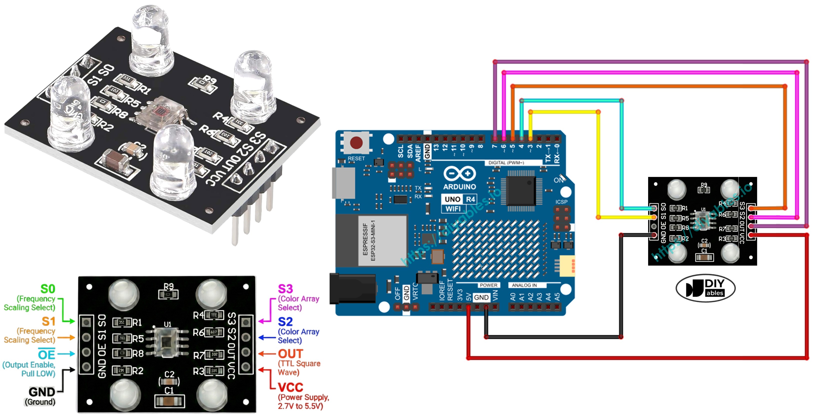
Wiring Diagram
This image shows how to connect the TCS3200 color sensor to Arduino UNO R4:
| TCS3200 Color Sensor | Arduino UNO R4 |
|---|---|
| VCC | 5V |
| GND | GND |
| S0 | Pin 4 |
| S1 | Pin 3 |
| S2 | Pin 6 |
| S3 | Pin 5 |
| OUT | Pin 7 |
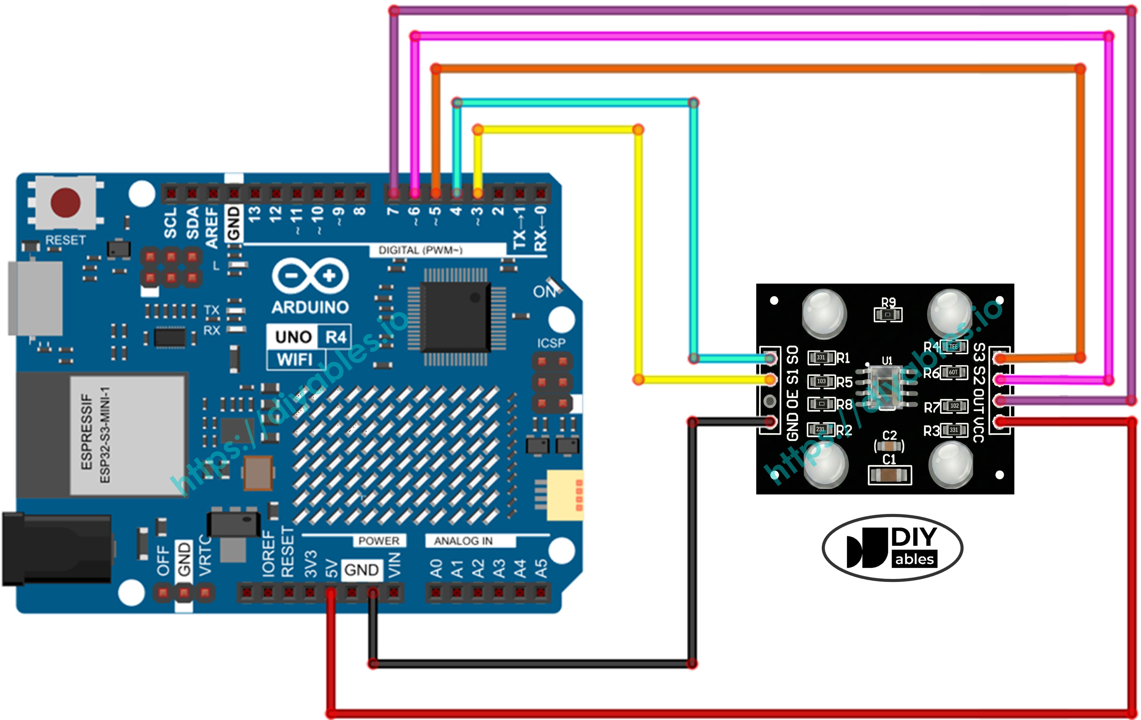
This image is created using Fritzing. Click to enlarge image
See The best way to supply power to the Arduino Uno R4 and other components.
Arduino UNO R4 Code - Calibration (Pulse Width)
Calibration is required because the sensor’s raw readings are affected by the environment. Factors such as LED brightness, distance, surface reflectivity, and ambient light change the measured values. You can think of these effects as “noise.” The first calibration step helps you measure that noise range (minimum and maximum for each color) so you can subtract its influence and map readings to correct 0–255 RGB values for your setup.
Detailed Instructions
Follow these instructions step by step:
- If this is your first time using the Arduino Uno R4 WiFi/Minima, refer to the tutorial on setting up the environment for Arduino Uno R4 WiFi/Minima in the Arduino IDE.
- Connect the Arduino Uno R4 board to the color sensor according to the provided diagram.
- Connect the Arduino Uno R4 board to your computer using a USB cable.
- Launch the Arduino IDE on your computer.
- Select the appropriate Arduino Uno R4 board (e.g., Arduino Uno R4 WiFi) and COM port.
- Copy the code above and open it in Arduino IDE.
- Click the Upload button in Arduino IDE to upload the code to Arduino UNO R4.
- Open the Serial Monitor. You will see continuous readings along with Min and Max values.
- Move the sensor over different objects: a white object (like paper), a black object, and optionally some colored objects.
- Watch the Min and Max rows update automatically as the sensor tracks the extremes.
- When the Min and Max values stop changing (usually after 10-20 seconds), those are your calibration values - write them down.
For example, from the output above, your calibration values would be:
- RedMin = 42, redMax = 210
- GreenMin = 55, greenMax = 185
- BlueMin = 60, blueMax = 172
Arduino UNO R4 Code - Read RGB values
Detailed Instructions
- In the code above, find these lines near the top:
- Replace ALL six 0 values with your calibration numbers from the previous step. For example, if your calibration gave you redMin = 42, redMax = 210, greenMin = 55, greenMax = 185, blueMin = 60, blueMax = 172, change the lines to:
- Upload the code to Arduino UNO R4.
- Place a colored object in front of the sensor.
- Check the result on the Serial Monitor.
The RGB values are now mapped to the standard 0-255 range. Lower pulse widths (more light) produce higher RGB values, and higher pulse widths (less light) produce lower RGB values.
Applications
Now that you can read RGB values, you can build projects like:
- Color sorter: Sort objects by color (red, green, blue)
- Color matching game: Check if two objects are the same color
- Line follower robot: Follow colored lines on the floor
- Quality control: Detect defective products by color
- Color-activated alarm: Trigger a buzzer or LED when a specific color is detected