Arduino Nano ESP32 - DIYables Bluetooth App Digital Pins
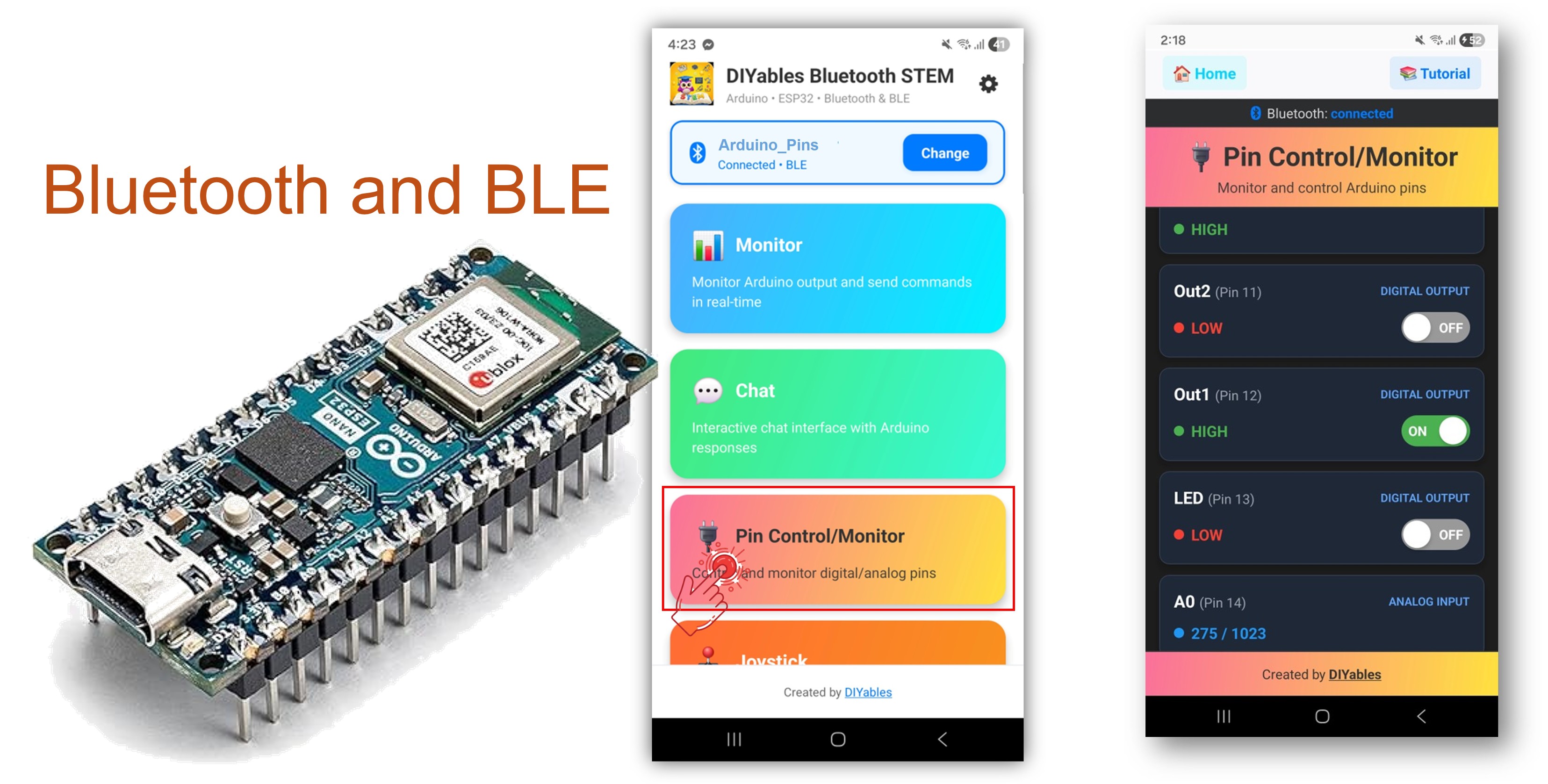
This example provides remote GPIO pin control and monitoring on the Arduino Nano ESP32 using BLE (Bluetooth Low Energy) via the DIYables Bluetooth STEM app. Control output pins and monitor input pins wirelessly from a smartphone. Suitable for relay control, button monitoring, LED switching, and any application requiring remote pin access.
Note: The Arduino Nano ESP32 supports BLE only — Classic Bluetooth is not supported. The DIYables Bluetooth App works on both Android and iOS with BLE.
Output Control : Set digital pins HIGH or LOW remotely
Input Monitoring : Read digital and analog pin states
Named Pins : Assign descriptive labels to each pin (e.g., "LED", "Relay")
Real-Time Updates : Push pin state changes to the app
Up to 16 Pins : Control multiple pins simultaneously
Android & iOS Support : BLE is compatible with both platforms
No Pairing Required : BLE connects without manual pairing
Or you can buy the following kits:
Disclosure: Some of the links provided in this section are Amazon affiliate links. We may receive a commission for any purchases made through these links at no additional cost to you.
Additionally, some of these links are for products from our own brand,
DIYables .
Connect the Arduino Nano ESP32 to your computer via USB.
Open Arduino IDE.
Select the Arduino Nano ESP32 board and the correct COM port.
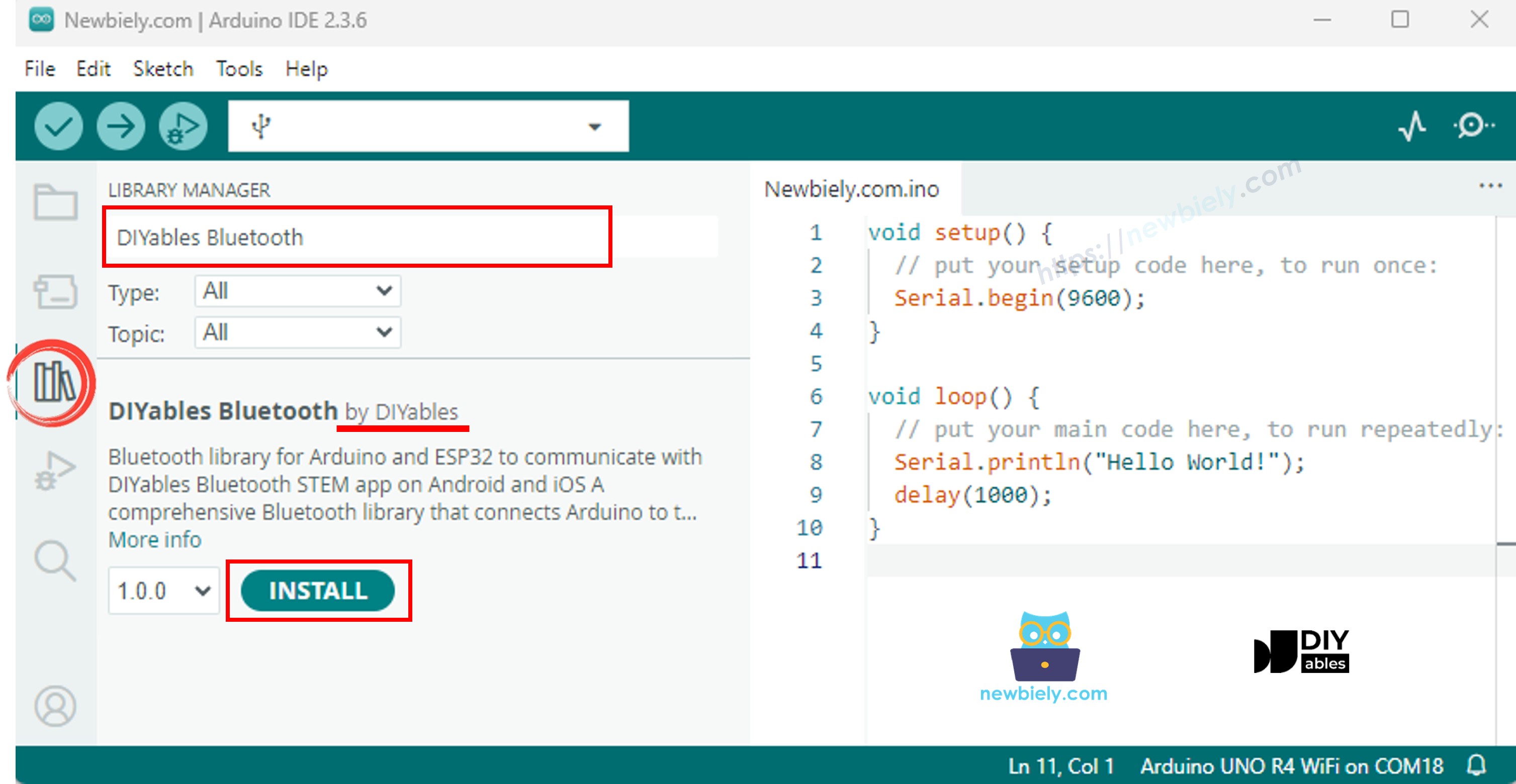
Click the Libraries icon in the left sidebar.
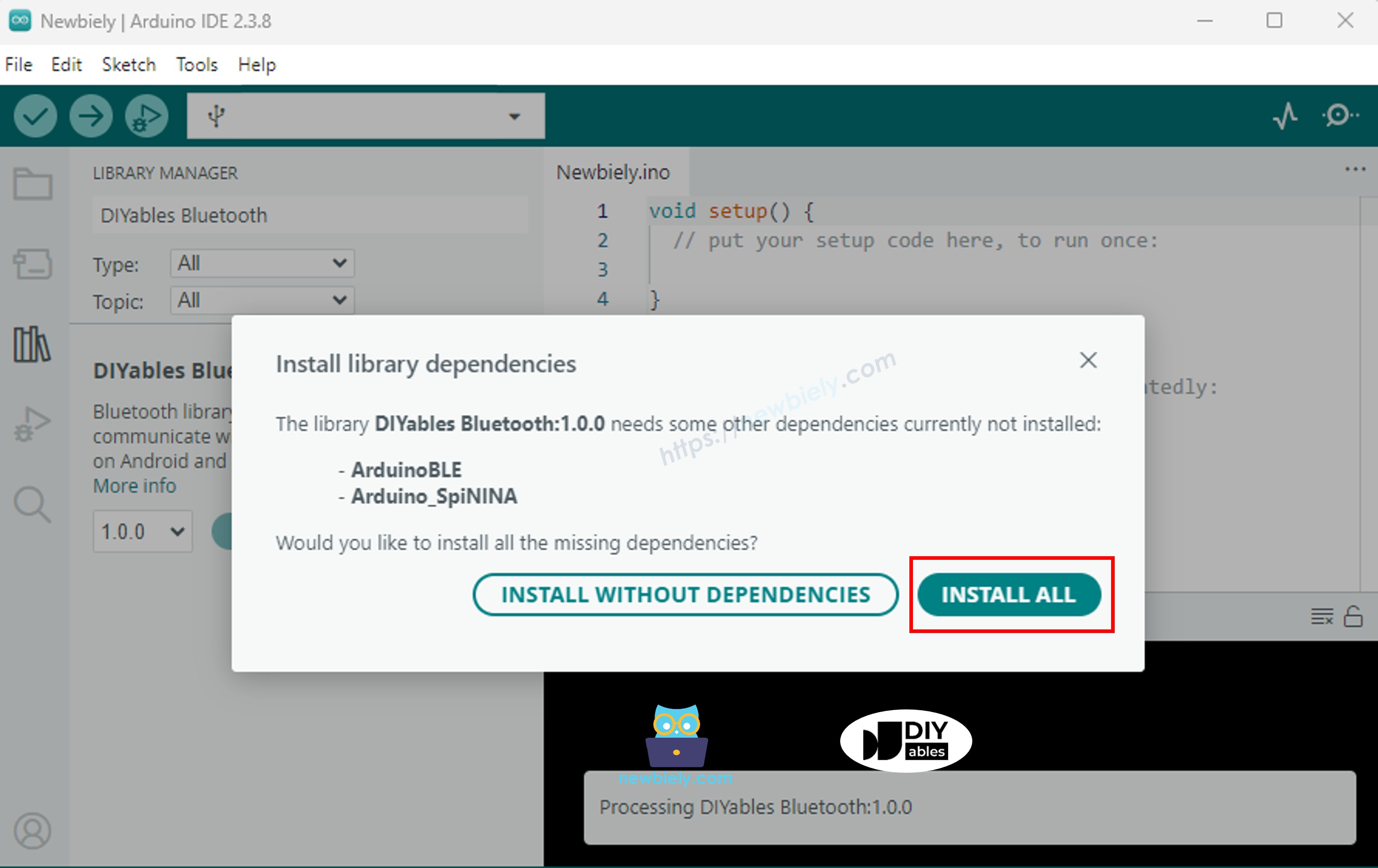
Search for "DIYables Bluetooth" and select the DIYables Bluetooth library by DIYables.
Click Install .
#include <DIYables_BluetoothServer .h>
#include <DIYables_BluetoothPinControl .h>
#include <platforms/DIYables_Esp32BLE.h>
const char* DEVICE_NAME = "ESP32BLE_Pins" ;const char* SERVICE_UUID = "19B10000-E8F2-537E-4F6C-D104768A1214" ;const char* TX_UUID = "19B10001-E8F2-537E-4F6C-D104768A1214" ;const char* RX_UUID = "19B10002-E8F2-537E-4F6C-D104768A1214" ;DIYables_Esp32BLE bluetooth(DEVICE_NAME, SERVICE_UUID, TX_UUID, RX_UUID);DIYables_BluetoothServer bluetoothServer(bluetooth);DIYables_BluetoothPinControl bluetoothPins;const int LED_PIN = LED_BUILTIN ; const int OUTPUT_PIN_1 = D6;const int OUTPUT_PIN_2 = D7;const int INPUT_PIN_1 = D4;const int INPUT_PIN_2 = D5;const int ANALOG_PIN_1 = A0; const int ANALOG_PIN_2 = A1; void setup () { Serial .begin (115200);
delay (1000);
Serial .println ("DIYables Bluetooth - ESP32 BLE Pin Control/Monitor Example" );
pinMode (LED_PIN, OUTPUT );
pinMode (OUTPUT_PIN_1, OUTPUT );
pinMode (OUTPUT_PIN_2, OUTPUT );
pinMode (INPUT_PIN_1, INPUT_PULLUP );
pinMode (INPUT_PIN_2, INPUT_PULLUP );
bluetoothServer.begin ();
bluetoothServer.addApp (&bluetoothPins);
bluetoothPins.enablePin (LED_PIN, BT_PIN_OUTPUT , "LED" );
bluetoothPins.enablePin (OUTPUT_PIN_1, BT_PIN_OUTPUT , "Out1" );
bluetoothPins.enablePin (OUTPUT_PIN_2, BT_PIN_OUTPUT , "Out2" );
bluetoothPins.enablePin (INPUT_PIN_1, BT_PIN_INPUT , "Btn1" );
bluetoothPins.enablePin (INPUT_PIN_2, BT_PIN_INPUT , "Btn2" );
bluetoothPins.enablePin (ANALOG_PIN_1, BT_PIN_INPUT , "A34" );
bluetoothPins.enablePin (ANALOG_PIN_2, BT_PIN_INPUT , "A35" );
bluetoothServer.setOnConnected ([]() {
Serial .println ("Bluetooth connected!" );
});
bluetoothServer.setOnDisconnected ([]() {
Serial .println ("Bluetooth disconnected!" );
});
bluetoothPins.onPinWrite ([](int pin, int state) {
digitalWrite (pin, state);
Serial .print ("Pin " );
Serial .print (pin);
Serial .print (" set to " );
Serial .println (state ? "HIGH" : "LOW" );
});
bluetoothPins.onPinRead ([](int pin) -> int {
int state;
if (pin == ANALOG_PIN_1 || pin == ANALOG_PIN_2) {
state = analogRead (pin);
Serial .print ("Analog pin " );
Serial .print (pin);
Serial .print (" read: " );
Serial .println (state);
} else {
state = digitalRead (pin);
Serial .print ("Digital pin " );
Serial .print (pin);
Serial .print (" read: " );
Serial .println (state ? "HIGH" : "LOW" );
}
return state;
});
bluetoothPins.onPinModeChange ([](int pin, int mode) {
pinMode (pin, mode == BT_PIN_OUTPUT ? OUTPUT : INPUT_PULLUP );
Serial .print ("Pin " );
Serial .print (pin);
Serial .print (" mode changed to " );
Serial .println (mode == BT_PIN_OUTPUT ? "OUTPUT" : "INPUT" );
});
Serial .println ("Waiting for Bluetooth connection..." );
Serial .print ("Enabled pins: " );
Serial .println (bluetoothPins.getEnabledPinCount ());
}
void loop () { bluetoothServer.loop ();
static unsigned long lastInputCheck = 0;
static int lastInputState1 = HIGH ;
static int lastInputState2 = HIGH ;
static int lastAnalogState1 = 0;
static int lastAnalogState2 = 0;
if (millis () - lastInputCheck >= 100) {
lastInputCheck = millis ();
int currentState1 = digitalRead (INPUT_PIN_1);
if (currentState1 != lastInputState1) {
lastInputState1 = currentState1;
bluetoothPins.updatePinState (INPUT_PIN_1, currentState1);
Serial .print ("Input pin " );
Serial .print (INPUT_PIN_1);
Serial .print (" changed to " );
Serial .println (currentState1 ? "HIGH" : "LOW" );
}
int currentState2 = digitalRead (INPUT_PIN_2);
if (currentState2 != lastInputState2) {
lastInputState2 = currentState2;
bluetoothPins.updatePinState (INPUT_PIN_2, currentState2);
Serial .print ("Input pin " );
Serial .print (INPUT_PIN_2);
Serial .print (" changed to " );
Serial .println (currentState2 ? "HIGH" : "LOW" );
}
int currentAnalog1 = analogRead (ANALOG_PIN_1);
if (abs (currentAnalog1 - lastAnalogState1) > 40) {
lastAnalogState1 = currentAnalog1;
bluetoothPins.updatePinState (ANALOG_PIN_1, currentAnalog1);
Serial .print ("Analog pin " );
Serial .print (ANALOG_PIN_1);
Serial .print (" changed to " );
Serial .println (currentAnalog1);
}
int currentAnalog2 = analogRead (ANALOG_PIN_2);
if (abs (currentAnalog2 - lastAnalogState2) > 40) {
lastAnalogState2 = currentAnalog2;
bluetoothPins.updatePinState (ANALOG_PIN_2, currentAnalog2);
Serial .print ("Analog pin " );
Serial .print (ANALOG_PIN_2);
Serial .print (" changed to " );
Serial .println (currentAnalog2);
}
}
delay (10);
}
∞
Newbiely | Arduino IDE 2.3.8
8
Serial .println ("Hello World!" );
Message (Enter to send message to 'Arduino Nano ESP32' on 'COM15')
DIYables Bluetooth - Pin Control/Monitor Example
Waiting for Bluetooth connection...
Enabled pins: 7
Ln 11, Col 1
Arduino Nano ESP32 on COM15
2
Install the DIYables Bluetooth App on your smartphone:
Android |
iOS
Note: The DIYables Bluetooth App works on both Android and iOS with BLE. No manual pairing is required.
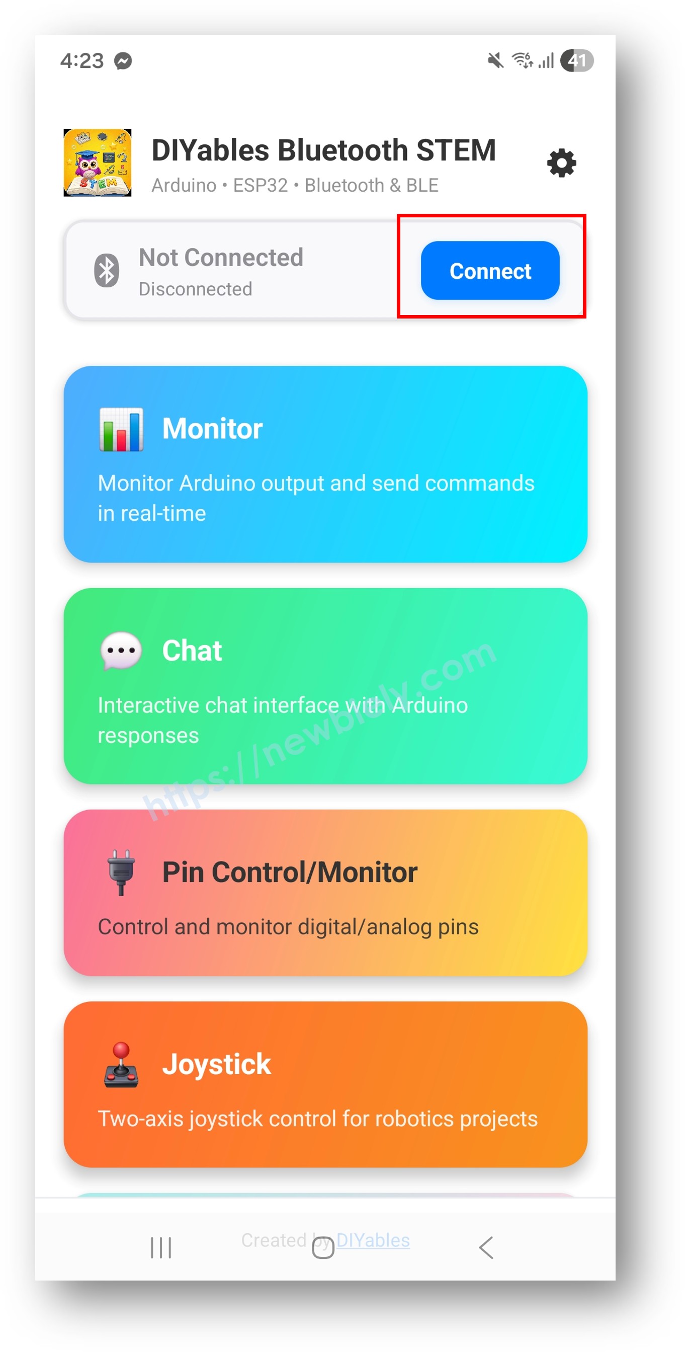
Launch the DIYables Bluetooth App.
On first launch, grant the following permissions:
Ensure Bluetooth is enabled on your device.
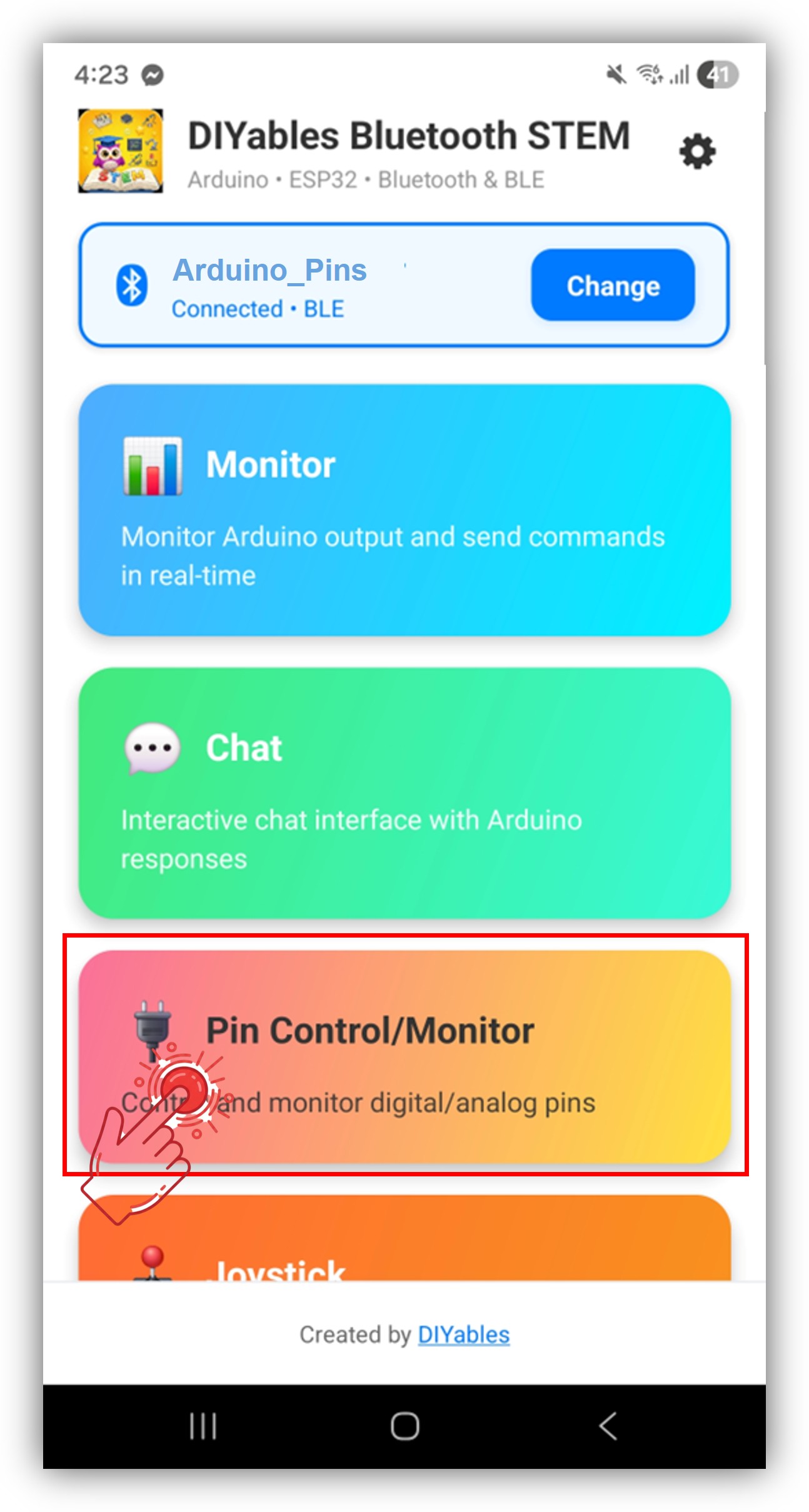
Tap Connect on the home screen. The app will scan for BLE devices.
Tap "Arduino_Pins" in the scan results.
After connecting, return to the home screen and open the Digital Pins app.
Tap the settings icon on the home screen to show or hide apps. See the DIYables Bluetooth App User Manual for details.
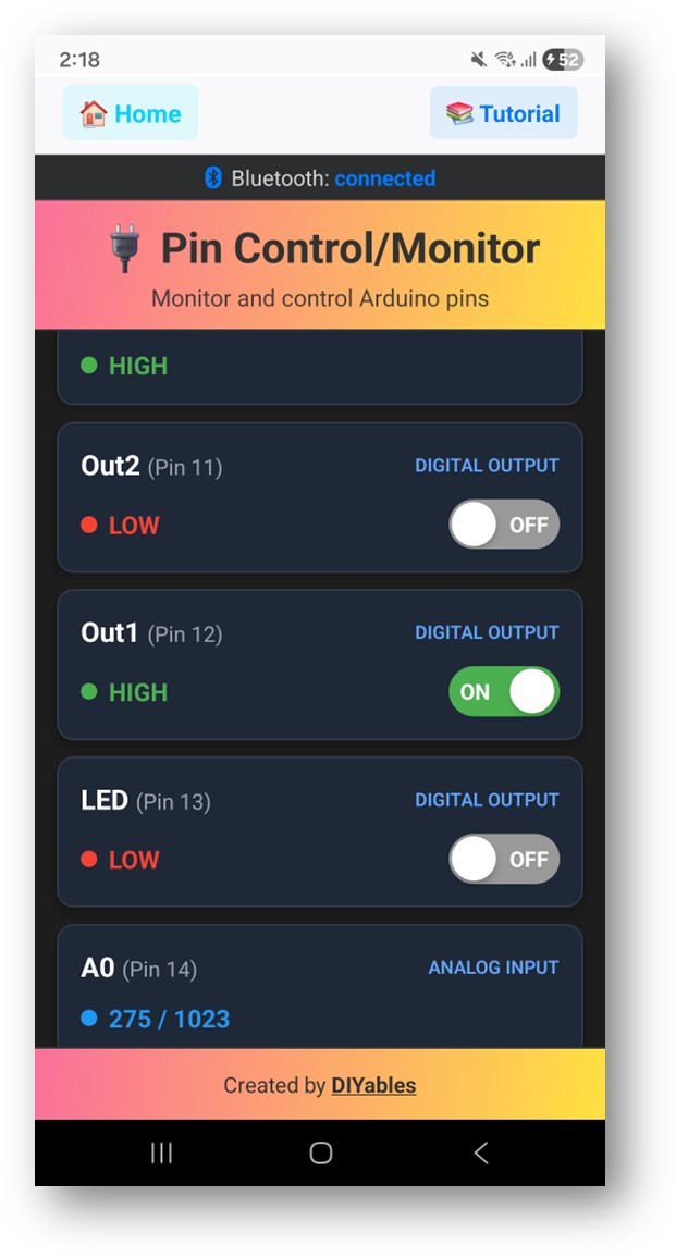
The enabled pins are listed with their names and current states.
Tap output pins to toggle HIGH /LOW, and observe input pin values update in real time.
Now look back at the Serial Monitor on Arduino IDE. You will see:
∞
Newbiely | Arduino IDE 2.3.8
8
Serial .println ("Hello World!" );
Message (Enter to send message to 'Arduino Nano ESP32' on 'COM15')
Bluetooth connected!
Pin 13 set to HIGH
Pin 13 set to LOW
Digital pin 7 read: HIGH
Ln 11, Col 1
Arduino Nano ESP32 on COM15
2
bluetoothPins.enablePin (13, BT_PIN_OUTPUT , "LED" );
bluetoothPins.enablePin (12, BT_PIN_OUTPUT , "Relay" );
bluetoothPins.enablePin (7, BT_PIN_INPUT , "Button" );
bluetoothPins.enablePin (A0, BT_PIN_INPUT , "Sensor" );
int count = bluetoothPins.getEnabledPinCount ();
bluetoothPins.onPinWrite ([](int pin, int state) {
digitalWrite (pin, state);
Serial .print ("Pin " );
Serial .print (pin);
Serial .println (state ? " ? HIGH" : " ? LOW" );
});
bluetoothPins.onPinRead ([](int pin) -> int {
if (pin >= A0) {
return analogRead (pin);
}
return digitalRead (pin);
});
bluetoothPins.onPinModeChange ([](int pin, int mode) {
pinMode (pin, mode == BT_PIN_OUTPUT ? OUTPUT : INPUT_PULLUP );
});
bluetoothPins.updatePinState (7, digitalRead (7));
bluetoothPins.updatePinState (A0, analogRead (A0));
const int RELAY_PIN = 12;const int BUTTON_PIN = 7;void setup () { pinMode (RELAY_PIN, OUTPUT );
pinMode (BUTTON_PIN, INPUT_PULLUP );
bluetoothPins.enablePin (RELAY_PIN, BT_PIN_OUTPUT , "Relay" );
bluetoothPins.enablePin (BUTTON_PIN, BT_PIN_INPUT , "Button" );
bluetoothPins.onPinWrite ([](int pin, int state) {
digitalWrite (pin, state);
});
}
void loop () { bluetoothServer.loop ();
static int lastState = HIGH ;
int state = digitalRead (BUTTON_PIN);
if (state != lastState) {
lastState = state;
bluetoothPins.updatePinState (BUTTON_PIN, state);
}
delay (10);
}
const int LED_PINS[] = {8, 9, 10, 11, 12, 13};const char* LED_NAMES[] = {"Red" , "Green" , "Blue" , "Yellow" , "White" , "Built-in" };const int NUM_LEDS = 6;void setup () { for (int i = 0; i < NUM_LEDS; i++) {
pinMode (LED_PINS[i], OUTPUT );
bluetoothPins.enablePin (LED_PINS[i], BT_PIN_OUTPUT , LED_NAMES[i]);
}
bluetoothPins.onPinWrite ([](int pin, int state) {
digitalWrite (pin, state);
});
}
1. Device not visible in the app
Confirm the board is powered on and the sketch is uploaded
Verify Bluetooth is enabled on your phone
On Android 11 and below, enable Location services as well
2. Pin toggle not working
3. Input pins not updating
4. Analog values not showing
5. Connection drops frequently
6. Upload fails or board not recognized
Multi-relay control panel
Button and switch monitor
LED lighting controller
Home automation switch panel
Sensor input dashboard
After completing the Bluetooth Digital Pins example, explore:
Bluetooth Slider — Analog value control
Bluetooth Monitor — Text-based status feedback
Bluetooth Table — Structured pin status display
Multiple Bluetooth Apps — Combine pin control with other app widgets