
ESP32 C3 Super Mini - Slide Switch
The ESP32 C3 Super Mini is about the size of a thumbnail, so it often ends up in very small boxes: a pocket BLE tag, a desk sensor, a tiny WiFi button. Such a gadget usually needs one setting that you change with a fingertip and that does not change back by itself - "beep" or "silent", "online" or "offline". The DIYables Mini Slide Switch SS12D10 is a good match. It is almost as small as the board, and its handle stays where you push it. Here, the C3 reads the switch on GPIO4 and tells you in the Serial Monitor whether it is ON or OFF.
In this tutorial, you'll learn:
- How the SS12D10 slide switch works, and which of its three unlabeled pins is COM
- Why pin 3 must go to 3.3V, and never to 5V, on the ESP32 C3 Super Mini
- How to wire the switch to GPIO4 with three wires and no resistor
- How to print the handle position at start-up and again after every move
- How a 50 ms second look filters out the contact bounce
- How to drop one wire with INPUT_PULLUP, and why ON then reads as LOW
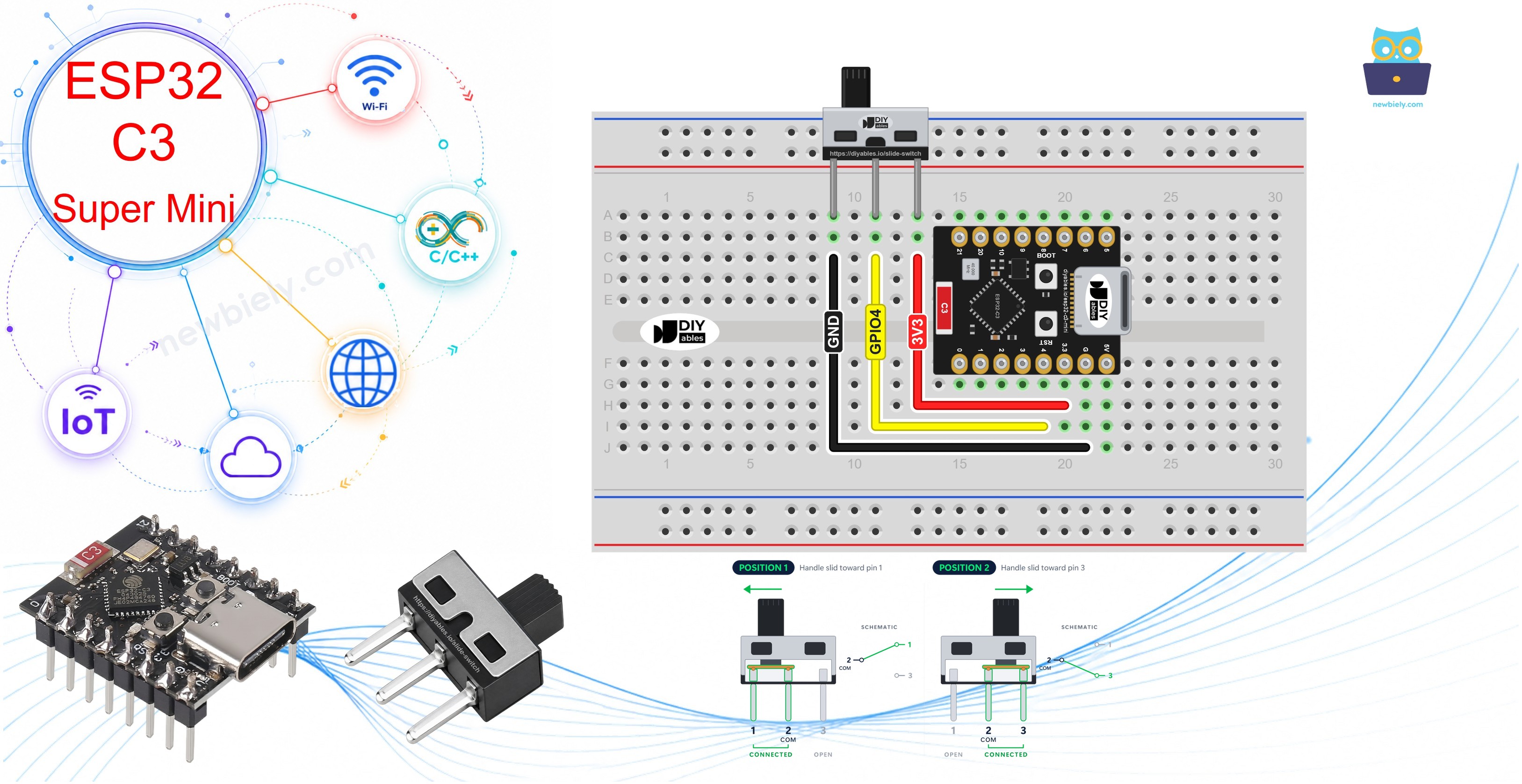
Hardware Preparation
| 1 | × | ESP32 C3 Super Mini | |
| 1 | × | USB Cable Type-A to Type-C (for USB-A PC) | |
| 1 | × | USB Cable Type-C to Type-C (for USB-C PC) | |
| 1 | × | Mini Slide Switch SS12D10 | |
| 1 | × | Breadboard | |
| 1 | × | Jumper Wires |
Or you can buy the following kits:
| 1 | × | DIYables Sensor Kit (18 sensors/displays) |
Additionally, some of these links are for products from our own brand, DIYables .
Overview of the Mini Slide Switch
The SS12D10 is a two-position switch that you move with the tip of a finger. A short plastic handle sticks out of the top, and three through-hole pins come out of the bottom in one row. Slide the handle to one end and it stays there - the switch is latching. A push button does the opposite: its spring lifts it back as soon as you let go. In parts lists, this type is called SPDT (single pole, double throw), or 1P2T.
Key Features:
- Contact type: SPDT (1P2T), 2 positions
- Pins: 3 in a row, 4.7 mm apart, 6.9 mm long
- Handle: 5 mm long
- Body size: about 12.8 x 6.7 x 18.2 mm
- Mounting: vertical, through-hole
- Contacts: silver-plated brass
- Rating: AC 125V 2A
- Lifetime: more than 100,000 switching cycles
- Operating temperature: -25°C to 80°C
The 125V 2A rating is the most the contacts can carry. In this project, only a tiny signal current flows into GPIO4, so it is far below that limit.
Why the Slide Switch is Great for Beginners:
- You can see the setting at a glance - the handle shows which side is chosen
- It keeps its position, so your code never needs to remember the last press
- With three wires, the input pin is always HIGH or LOW, so there are no random readings
- No library is needed, only pinMode() and digitalRead()
Slide Switch Pinout
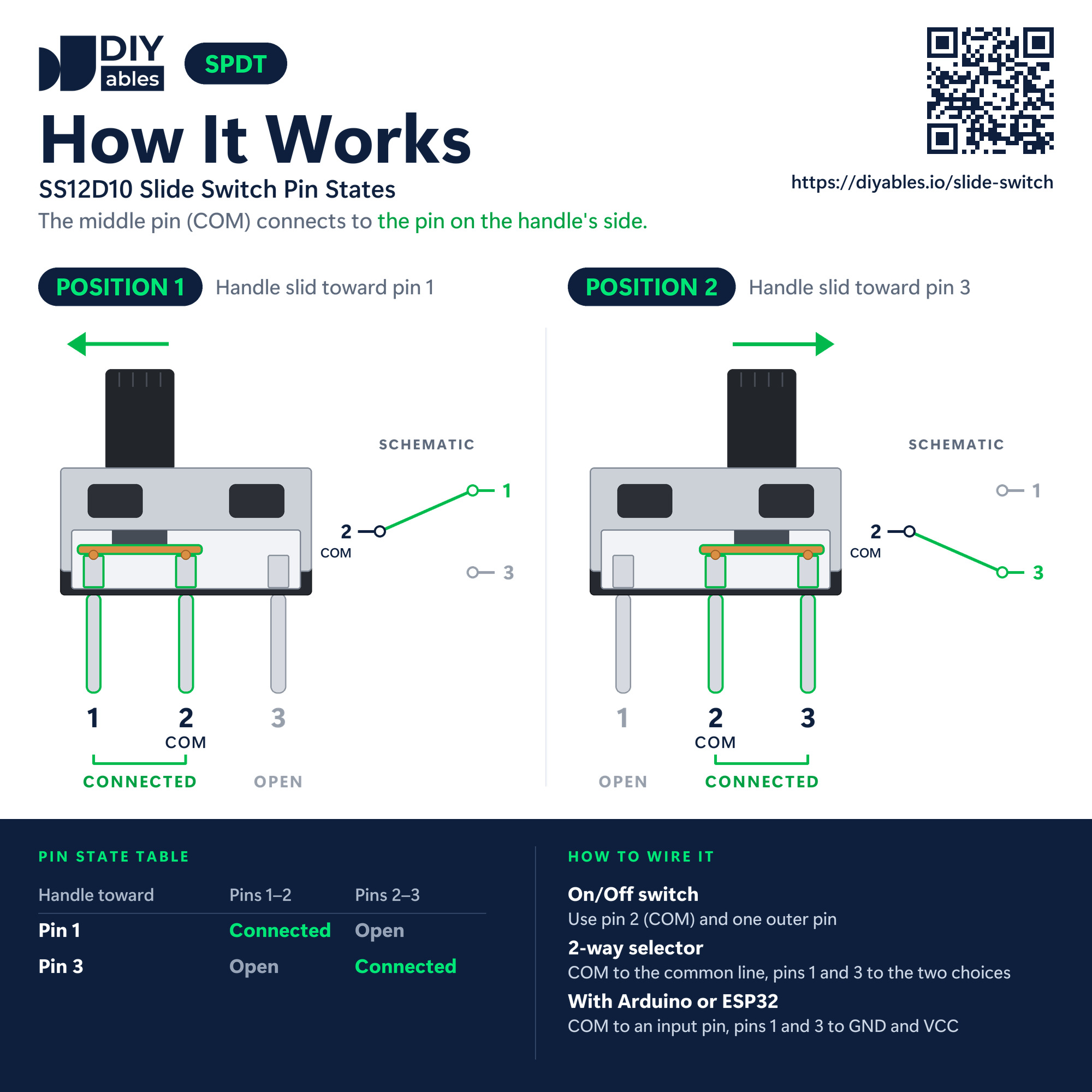
Nothing is printed on the switch. Just remember: the middle pin is always COM, and the two outer pins are pin 1 and pin 3.
- Pin 1: outer pin. Connect this pin to GND of the ESP32 C3 Super Mini
- Pin 2 (COM): the middle, common pin. Connect it to GPIO4. It carries the voltage of whichever outer pin the handle joins it to
- Pin 3: outer pin. Connect it to the 3.3V pin (leave it free in the 2-wire version)
Inside the body, a small metal bridge always touches COM. It also touches the outer pin on the side where the handle is:
- Handle toward pin 1: pins 1 and 2 are connected, pin 3 is open
- Handle toward pin 3: pins 2 and 3 are connected, pin 1 is open
※ NOTE THAT:
Slide switch, ON/OFF switch or button? All three give you HIGH or LOW on one pin. The ON/OFF switch is a bigger panel switch with two pins, made to turn a whole device on and off. The button and the button module spring back, so they suit short events like "next" or "start". Need four or eight settings at once? A DIP switch is a row of tiny slide switches in one block.
Wiring Diagram between Slide Switch and ESP32 C3 Super Mini
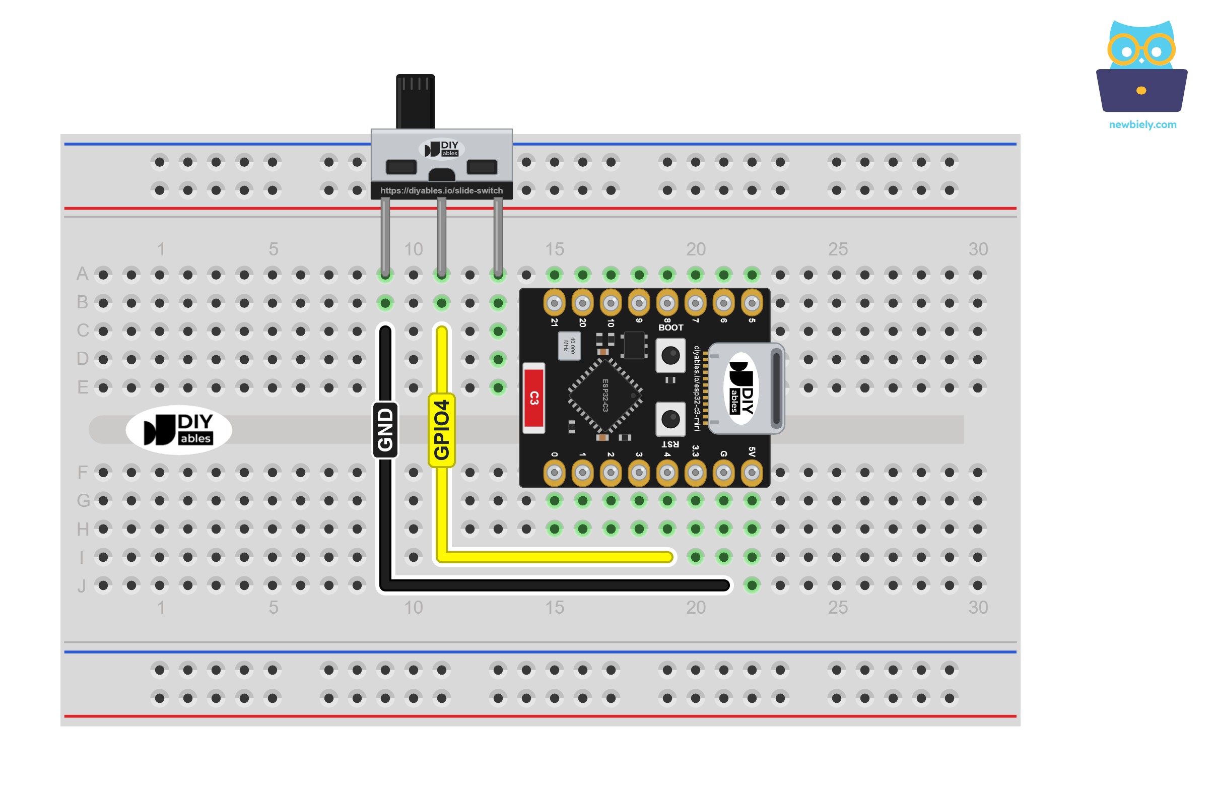
Plug the ESP32 C3 Super Mini and the slide switch into the same breadboard. Then run one wire from the hole next to each board pin to a hole in the column of the matching switch pin: GND to pin 1, GPIO4 (written as 4 in the code) to COM, and 3.3V to pin 3. No resistor is needed, because COM always touches either GND or 3.3V, so GPIO4 never floats.
Why GPIO4? It is not a strapping pin (GPIO2, GPIO8 and GPIO9 are), and it sits on the same side of the board as 3V3 and GND, so all three wires stay short.
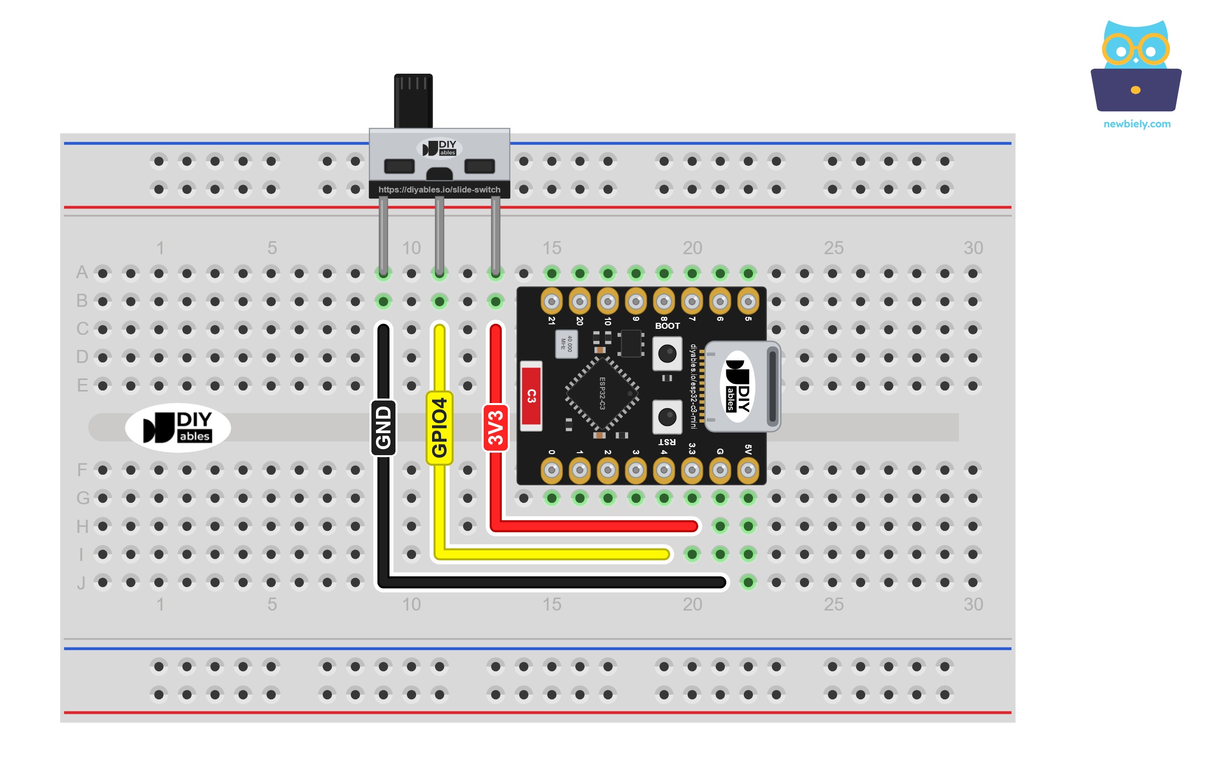
This image is created using Fritzing. Click to enlarge image
| Slide Switch Pin | ESP32 C3 Super Mini Pin |
|---|---|
| Pin 1 | GND |
| Pin 2 (COM) | GPIO4 |
| Pin 3 | 3.3V |
※ NOTE THAT:
Two rules keep the board safe:
- Pin 3 goes to 3.3V, never to 5V. With the handle toward pin 3, COM passes the pin 3 voltage straight to GPIO4. The ESP32-C3 pins are made for 3.3V only, and 5V can damage them.
- GPIO4 stays an input. Never set it to OUTPUT while the switch is connected. The switch ties the pin directly to 3.3V or GND, so an output level that disagrees would cause a short.
Good to know: leave GPIO20 and GPIO21 free for this project. They are the serial RX and TX pins of the board. For a build that lasts, solder the wires to the switch legs instead of only pushing them on.
ESP32 C3 Super Mini Code - Slide Switch (3 Wires)
The sketch tells you where the handle is the moment the board starts. After that it stays quiet, and it prints one new line only when you move the handle.
What the code does:
- Sets GPIO4 as a plain INPUT - the switch itself pulls the pin up or down
- Reads the handle once in setup() and prints the start position
- Checks GPIO4 over and over in loop()
- When the level looks different, waits 50 ms for the contacts to settle and reads once more
- Prints "ON" for HIGH (handle toward pin 3) or "OFF" for LOW (handle toward pin 1), but only if the change is still there
- Ignores a short glitch that is gone after the wait
Detailed Instructions
- New to ESP32 C3 Super Mini? Do our Getting Started with ESP32 C3 Super Mini tutorial first, so the ESP32 board package is ready in the Arduino IDE.
- Make the circuit: Put the board and the switch on the breadboard, then add the three wires from the table: pin 1 to GND, COM to GPIO4, pin 3 to 3.3V.
- Connect the board: Plug the ESP32 C3 Super Mini into your computer with a USB Type-C cable.
- Open Arduino IDE: Select the ESP32 C3 Super Mini board and its COM port.
- Copy the sketch: Paste the code above into a new sketch. There is no library to install.
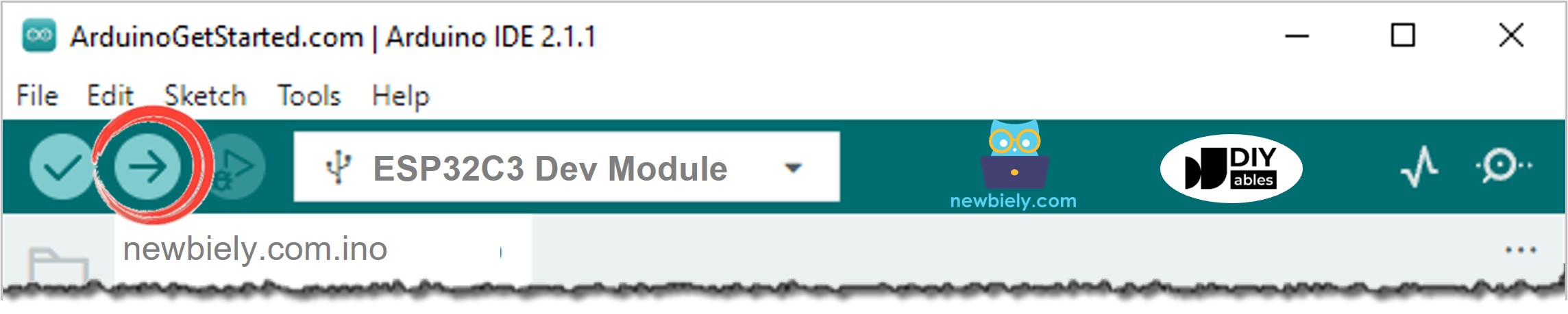
- Upload: Click the Upload button and wait until it is done.
- Open Serial Monitor: Set it to 115200 baud. To see the start line again, press the RST button on the board.
- Move the handle: Start with the handle toward pin 1, then slide it across three times. You get one line per move:
- Pro Tip: If ON shows up when the handle points at pin 1, the GND and 3.3V wires are swapped. It does no harm: swap the two outer wires, or swap the two messages in the code. If the reading never changes, check that the middle pin, not an outer one, goes to GPIO4. An empty Serial Monitor usually means USB CDC On Boot is Disabled in the Tools menu - enable it and upload again.
Line-by-line Code Explanation
The above ESP32 C3 Super Mini code contains line-by-line explanation. Please read the comments in the code!
ESP32 C3 Super Mini Code - Slide Switch with INPUT_PULLUP (2 Wires)
Want one wire less, and no 3.3V wire at all? Every GPIO of the ESP32-C3 has a pull-up resistor inside, and INPUT_PULLUP turns it on. So you can just remove the pin 3 wire. GND and GPIO4 stay as they are.
This image is created using Fritzing. Click to enlarge image
| Slide Switch Pin | ESP32 C3 Super Mini Pin |
|---|---|
| Pin 1 | GND |
| Pin 2 (COM) | GPIO4 |
| Pin 3 | Not connected |
Be careful, the logic is now upside down:
- Handle toward pin 1: COM is joined to GND, GPIO4 reads LOW, and the sketch prints ON
- Handle toward pin 3: COM touches nothing, the pull-up holds GPIO4 HIGH, and the sketch prints OFF
What the code does:
- Sets GPIO4 as INPUT_PULLUP, so the pin rests at HIGH when COM is open
- Uses the same start-up read and 50 ms bounce check as the first sketch
- Treats LOW as ON and HIGH as OFF
Detailed Instructions
- Change the wiring: Take the pin 3 wire off the 3.3V hole. Keep the GND and GPIO4 wires.
- Upload: Paste this sketch into the Arduino IDE and click Upload.
- Open Serial Monitor: Keep 115200 baud and press the RST button once.
- Try it: This time, start with the handle toward pin 3 and slide it across four times:
- Pro Tip: Leave pin 3 empty in this version. If pin 3 went to GND, both handle positions would read LOW, and the sketch could never see OFF.
Line-by-line Code Explanation
The above ESP32 C3 Super Mini code contains line-by-line explanation. Please read the comments in the code!
Applications and Project Ideas
A slide switch is the right part for a setting that you choose once and then leave alone. Some ideas for the ESP32 C3 Super Mini:
- Online or offline: read the switch in setup() and only start WiFi when it is ON, to save battery
- Silent mode: mute the buzzer of an alarm or a timer without changing the code
- Celsius or Fahrenheit: pick the unit for a temperature sensor display
- Setup mode: with the switch ON at power-up, open a WiFi hotspot for the settings page
- BLE tag on/off: stop a small Bluetooth beacon from sending without pulling out the battery
- Data logger: start and stop saving readings with one slide
Video Tutorial
Challenge Yourself
Practice what you learned with these tasks:
- Easy: Light the onboard blue LED (GPIO8) while the switch is ON - see ESP32 C3 Super Mini - LED - Blink for LED code
- Easy: Count how many times the handle has moved and print the number with each line
- Medium: Add a second slide switch on GPIO3 and print one of four modes: 00, 01, 10 or 11
- Medium: Make an LED blink fast when the switch is ON and slowly when it is OFF, without using delay()
- Advanced: Read the switch only once in setup() and join your WiFi network only when it is ON
- Advanced: Show the switch position on a web page hosted by the ESP32 C3 Super Mini