Arduino Nano - RFID
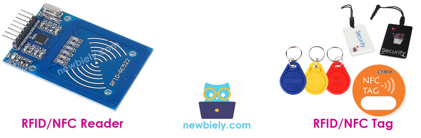
This tutorial instructs you how to use RFID/NFC with Arduino Nano. The RFID/NFC system consists of two components: a reader and a tag. Two of the most popular RFID/NFC readers are the RC522 and PN532. This tutorial will uses the RC522 RFID/NFC reader, which is cheap and easy to use.
The RC522 RFID/NFC reader can:
- Obtains the UID of an RFID/NFC tag
- Changes the UID of an RFID/NFC tag (only if the tag supports this)
- Stores data onto an RFID/NFC tag
- Retrieves data from an RFID/NFC tag
This tutorial focuses on:
- How to connect RC522 module to Arduino Nano
- How to program Arduino Nano to communicate with RC522 module to read UID of RFID tag.
Hardware Preparation
Or you can buy the following kits:
| 1 | × | DIYables Sensor Kit (18 sensors/displays) |
Additionally, some of these links are for products from our own brand, DIYables .
Overview of RFID-RC522 Module
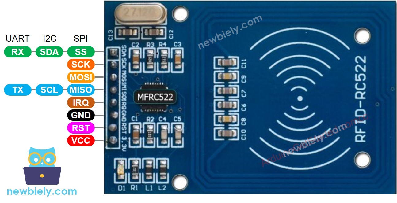
RFID-RC522 Module Pinout
The RFID-RC522 has 8 pins, some of which are general pins and the others are shared among three communication modes: SPI, I2C, and UART. It is only possible to use one of these modes at a time. The pins are:
- GND pin: This needs to be connected to ground (0V).
- VCC pin: This needs to be connected to the voltage supply (3.3V).
- RST pin: This is a reset and power-down pin. When this pin goes low, it enables hard power-down. On the rising edge, the module is reset.
- IRQ pin: This is an interrupt pin that can alert the microcontroller when an RFID tag comes into its vicinity.
- MISO/SCL/TX pin: This acts as MISO when SPI interface is enabled, SCL when I2C interface is enabled, and TX when UART interface is enabled.
- MOSI pin: This acts as MOSI when SPI interface is enabled.
- SCK pin: This acts as SCK when SPI interface is enabled.
- SS/SDA/RX pin: This acts as SS when SPI interface is enabled, SDA when I2C interface is enabled, and RX when UART interface is enabled.
※ NOTE THAT:
- The arrangement of pins may differ depending on the manufacturer. It is essential to use the labels printed on the module, as illustrated in the image above from DIYables manufacturer.
- Do not connect the VCC pin to the 5V pin, as this could damage the module.
- The MFRC522 library only supports SPI mode, so this tutorial will focus on SPI communication.
How RFID/NFC Works
RFID/NFC is composed of two parts: a reader and a tag.
- The reader is made up of a radio frequency module and an antenna that produces a high frequency electromagnetic field.
- The tag is normally a passive device, meaning it does not require a power source. It has a microchip that stores and processes information, as well as an antenna to receive and transmit a signal. This tag is used to store the data and its unique ID.
The tag must be close to the reader in order to read the information it contains. The process involves the reader generating an electromagnetic field, which causes electrons to move through the tag's antenna and power the chip. The chip then sends the requested information back to the reader as a radio signal. The reader detects this signal and transforms it into data, which is then read by Arduino Nano.
Wiring Diagram between RFID-RC522 Module and Arduino Nano
The RFID-RC522 Module requires a voltage of 3.3V, but Arduino output pins provide 5V. Thus:
- To ensure safety, the voltage from the Arduino pins should be regulated to 3.3V before connecting to the RC522 Module.
- For testing purposes, the Arduino pins can be directly connected to the RC522 Module, but it might cause issues in some cases.
This tutorial provide two different wiring diagrams for both cases:
- Wiring Diagram between RC522 and Arduino without voltage regulator
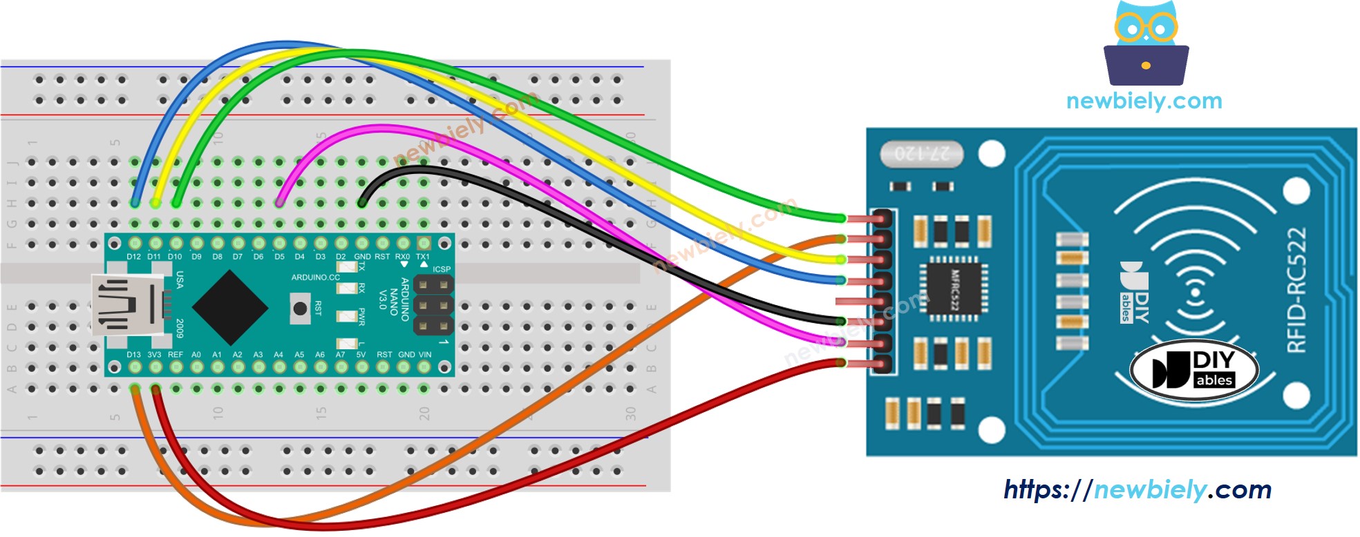
This image is created using Fritzing. Click to enlarge image
- Wiring Diagram between RC522 and Arduino with voltage regulator
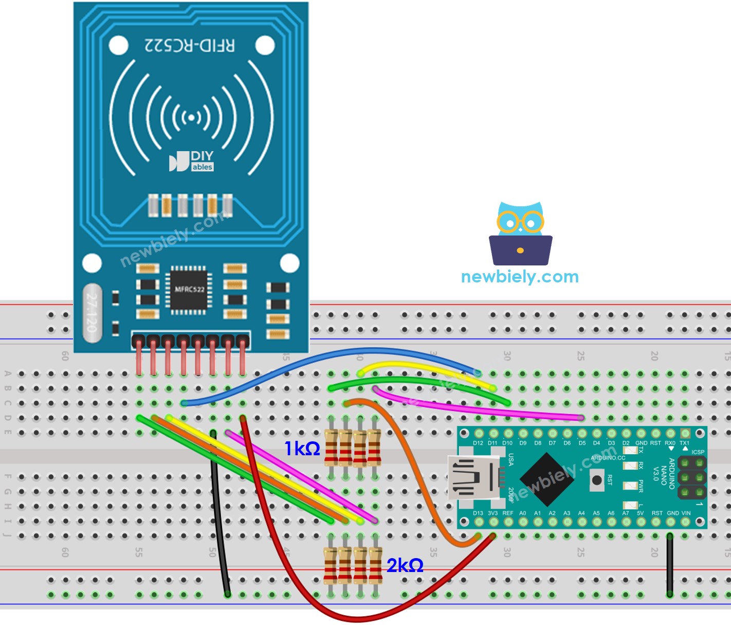
This image is created using Fritzing. Click to enlarge image
See The best way to supply power to the Arduino Nano and other components.
As indicated in the above wiring diagram, pairs of resistors with values of 1kOhm and 2kOhm are utilized to regulate 5V to 3.3V.
- It does not need to regulate the voltage between the Arduino pin and the MISO pin of the RC522 module.
- However, it needs to regulate the voltage between the Arduino pins and the SS, SCK, MOSI, and RST pins of the RC522 module.
Wiring table of RFID/NFC RC522 Module and Arduino Nano
| RFID/NFC RC522 | Arduino Nano |
|---|---|
| SS | → 10 |
| SCK | → 13 |
| MOSI | → 11 |
| MISO | → 12 |
| IRQ | not connected |
| GND | → GND |
| RST | → 5 |
| VCC | → 3.3V |
Arduino Nano RFID/NFC Code
Detailed Instructions
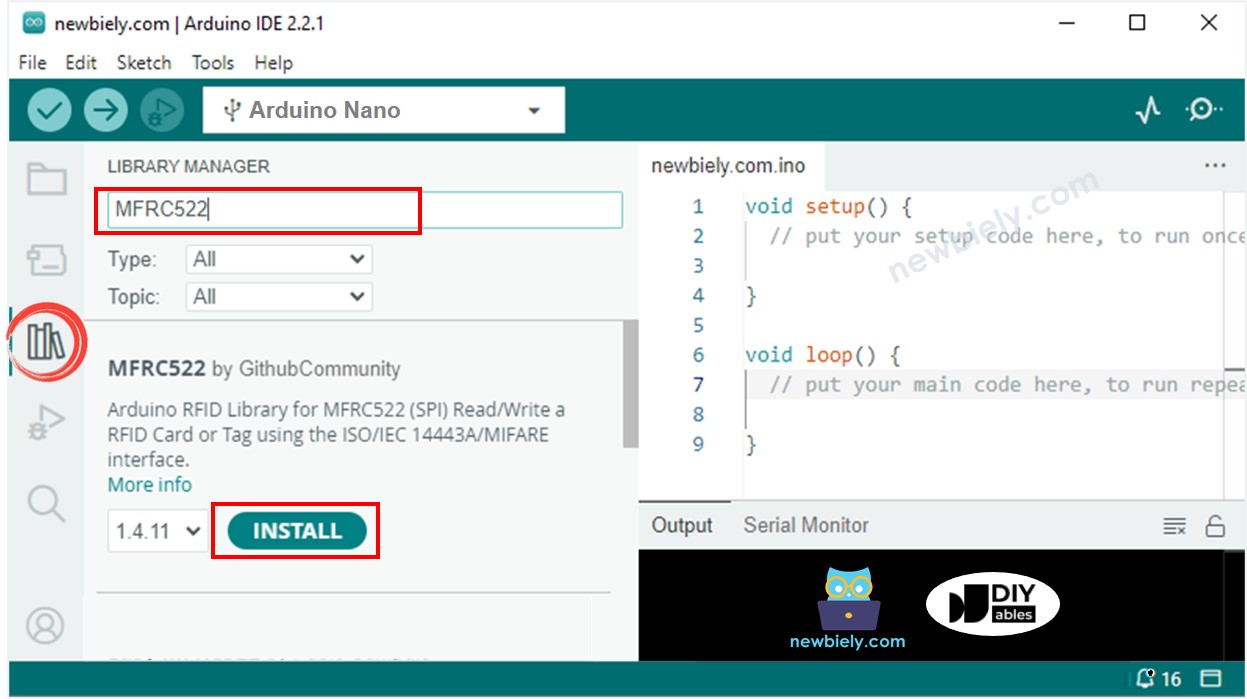
- Click to the Libraries icon on the left bar of the Arduino IDE.
- Search for “MFRC522” and locate the library by GithubCommunity.
- Then, press the Install button to install the MFRC522 library.
- Copy the code above and open it with the Arduino IDE.
- Click the Upload button in the Arduino IDE to compile and upload the code to the Arduino Nano.
- Open the Serial Monitor.
- Tap several RFID/NFC tags onto the RFID-RC522 module.
- Check the UID on the Serial Monitor.