Arduino Nano - Motion Sensor - LED
This tutorial instructs you how to use Arduino Nano and motion sensor to control LED. In detail:
- Arduino Nano turns on the LED when motion is detected
- Arduino Nano turns off the LED when motion is not sensed
This can be applied in an automation process that triggers actions upon detecting human presence.
Hardware Preparation
Or you can buy the following kits:
| 1 | × | DIYables Sensor Kit (18 sensors/displays) |
Disclosure: Some of the links provided in this section are Amazon affiliate links. We may receive a commission for any purchases made through these links at no additional cost to you.
Additionally, some of these links are for products from our own brand, DIYables .
Additionally, some of these links are for products from our own brand, DIYables .
Buy Note: Use the LED Module for easier wiring. It includes an integrated resistor.
Overview of LED and Motion Sensor
If you are unfamiliar with LED and motion sensor (including pinout, functionality, and programming), the following tutorials can help:
Wiring Diagram
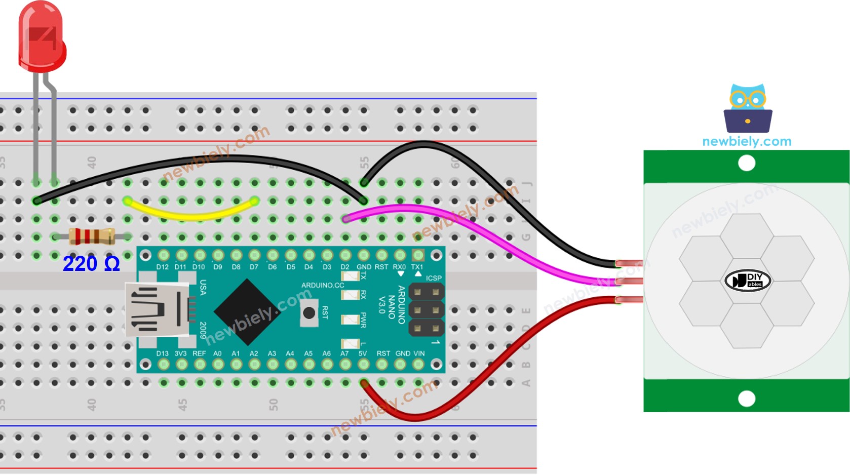
This image is created using Fritzing. Click to enlarge image
See The best way to supply power to the Arduino Nano and other components.
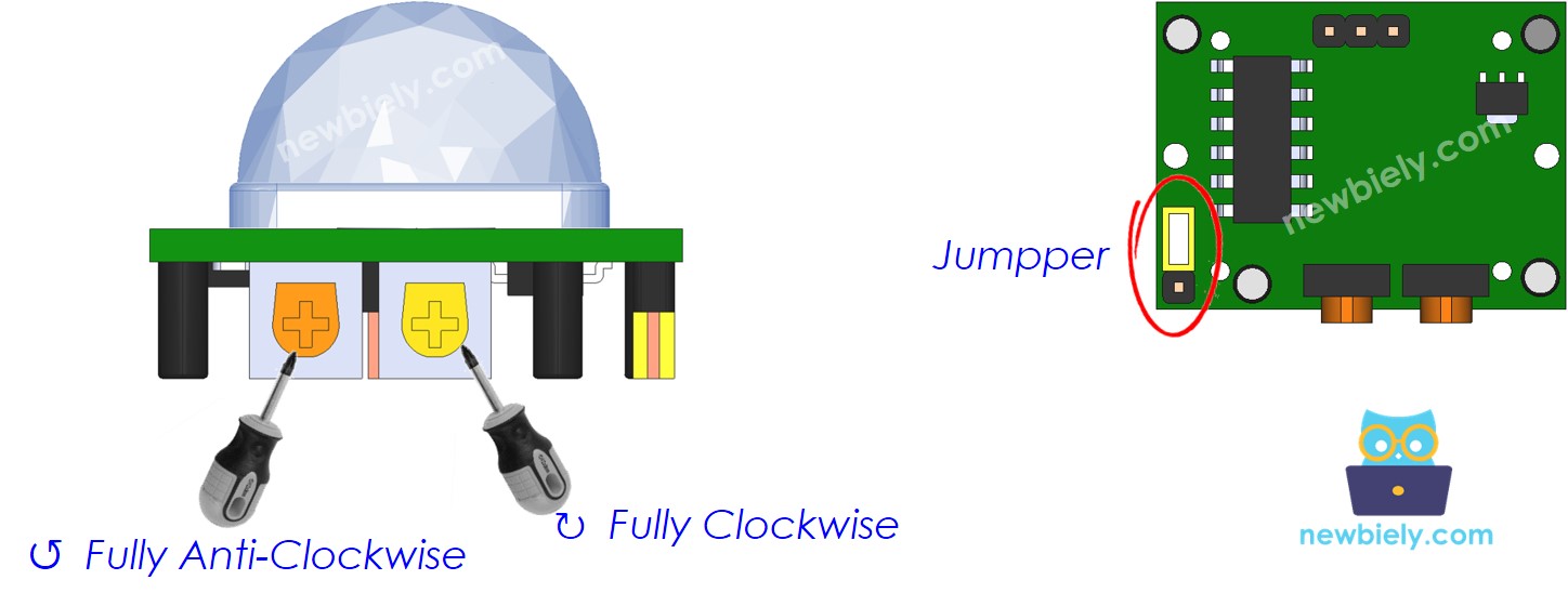
Initial Setting
| Time Delay Adjuster | Screw it in anti-clockwise direction fully. |
| Detection Range Adjuster | Screw it in clockwise direction fully. |
| Repeat Trigger Selector | Put jumper as shown on the image. |
Arduino Nano Code
/*
* This Arduino Nano code was developed by newbiely.com
*
* This Arduino Nano code is made available for public use without any restriction
*
* For comprehensive instructions and wiring diagrams, please visit:
* https://newbiely.com/tutorials/arduino-nano/arduino-nano-motion-sensor-led
*/
#define MOTION_SENSOR_PIN 2 // The Arduino Nano pin connected to the OUTPUT pin of motion sensor
#define LED_PIN 7 // The Arduino Nano pin connected to the LED
int motion_state = LOW; // current state of motion sensor's pin
int prev_motion_state = LOW; // previous state of motion sensor's pin
void setup() {
Serial.begin(9600); // Initialize the Serial to communicate with the Serial Monitor.
pinMode(MOTION_SENSOR_PIN, INPUT); // set arduino pin to input mode
pinMode(LED_PIN, OUTPUT); // set arduino pin to output mode
}
void loop() {
prev_motion_state = motion_state; // store old state
motion_state = digitalRead(MOTION_SENSOR_PIN); // read new state
if (prev_motion_state == LOW && motion_state == HIGH) { // pin state change: LOW -> HIGH
Serial.println("Motion detected!");
digitalWrite(LED_PIN, HIGH); // turn on
}
else if (prev_motion_state == HIGH && motion_state == LOW) { // pin state change: HIGH -> LOW
Serial.println("Motion stopped!");
digitalWrite(LED_PIN, LOW); // turn off
}
}
Detailed Instructions
- Connect your Arduino Nano to your computer using a USB cable.
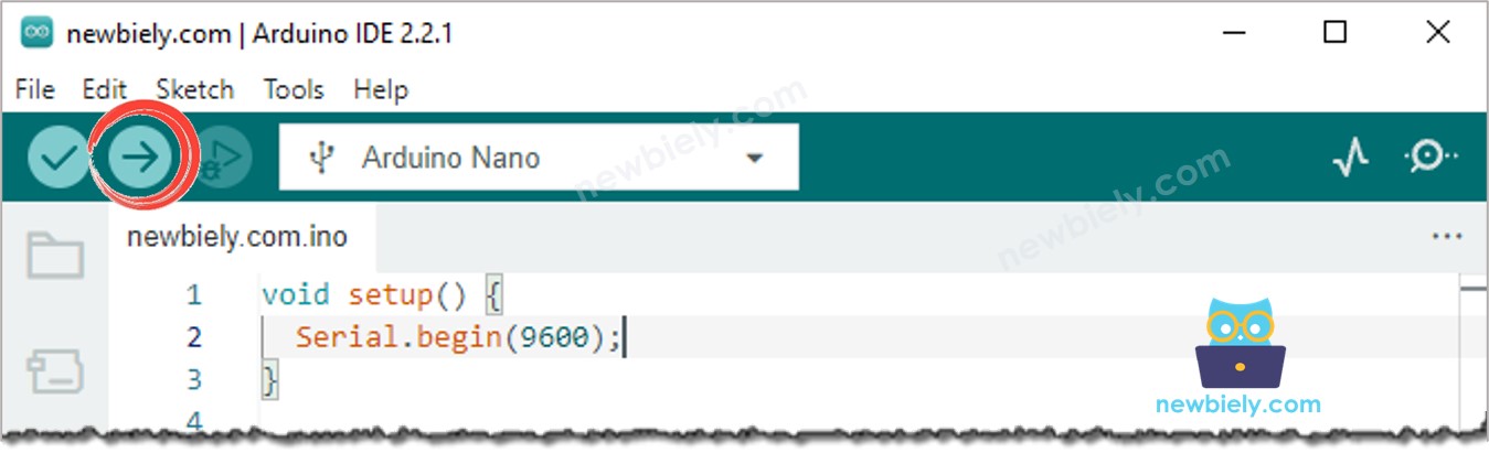
- Launch the Arduino IDE, select the appropriate board and port.
- Copy the code above and open it in the Arduino IDE.
- Click the Upload button in the Arduino IDE to upload the code to the Arduino Nano.
- Move your hand in front of the sensor and observe the alteration in the state of the LED.
Code Explanation
Check out the line-by-line explanation contained in the comments of the source code!