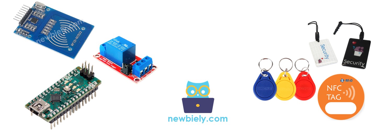
This tutorial instructs you how to use an Arduino Nano, RFID NFC RC522 module to control a relay. You can further extend this tutorial by using the relay to control motors, actuators, door lock, light bulb, and more.
Disclosure: Some of the links provided in this section are Amazon affiliate links. We may receive a commission for any purchases made through these links at no additional cost to you. Additionally, some of these links are for products from our own brand, DIYables .
Overview of RFID/NFC RC522 Module and Relay
If you are unfamiliar with the RFID/NFC RC522 Module and relay (pinout, how it works, how to program ...), you can find out more in the following tutorials:
The RFID/NFC reader reads the UID from the tag when a user taps it.
Arduino Nano then obtains the UID from the reader.
It compares this UID with the UIDs that have been predefined in the Arduino Nano code.
If the UID matches one of the predefined UIDs, the Arduino Nano will activate the relay.
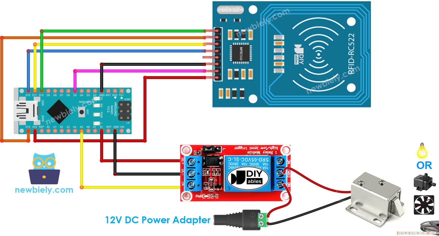
Wiring Diagram
This image is created using Fritzing. Click to enlarge image
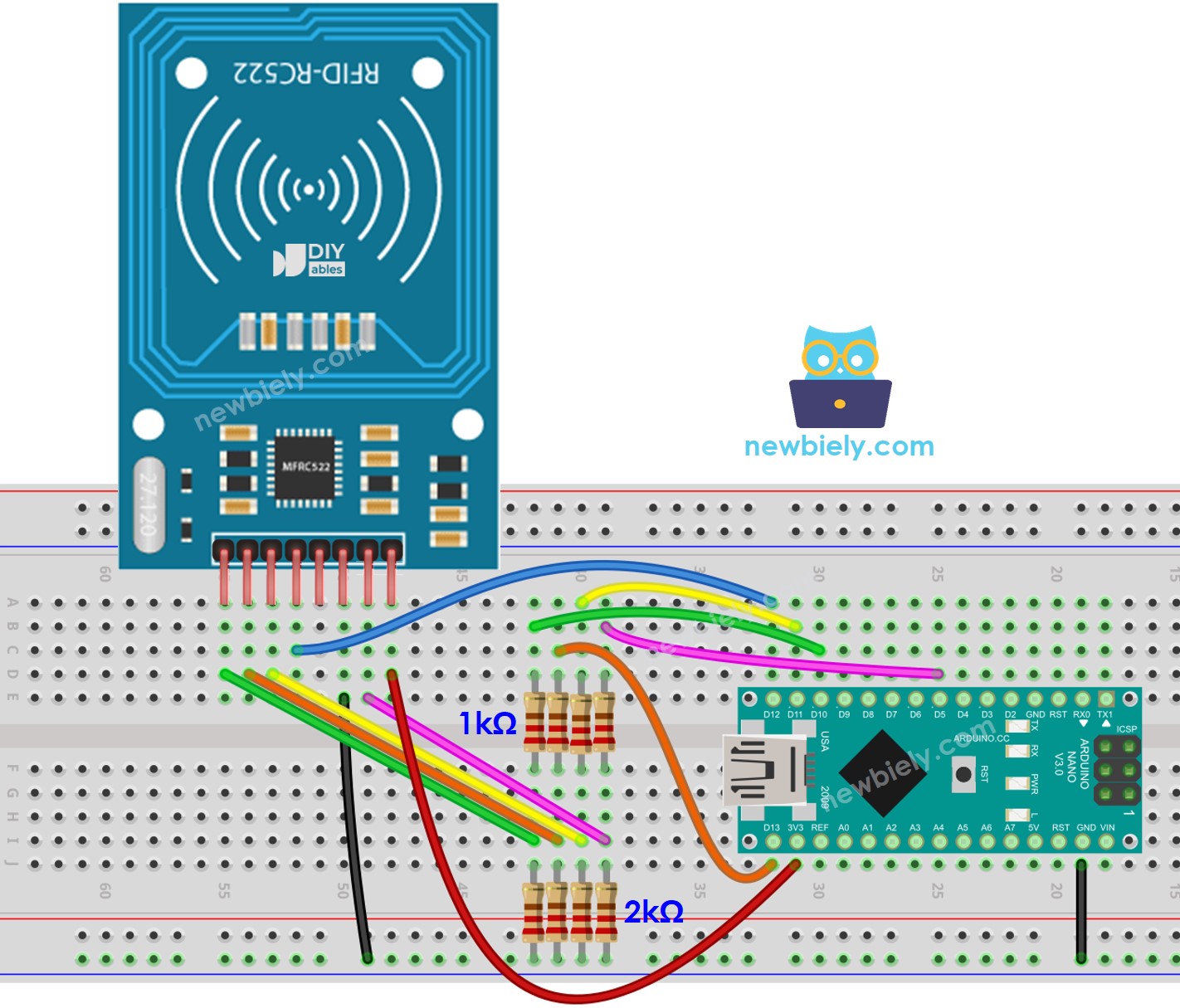
To simplify the connection, the pins of the RC522 module are directly connected to the pins of the Arduino. However, in certain cases, this can cause the Arduino to malfunction since its output pins generate 5V, while the pins of the RC522 module operate normally at 3.3V. Therefore, it is advisable to regulate the voltage between the pins of the Arduino and the RC522 module. For further details, please refer to the Arduino Nano - RFID RC522 tutorial. The diagram below illustrates how to regulate 5V to 3.3V using resistors:
This image is created using Fritzing. Click to enlarge image
The arrangement of pins may differ depending on the manufacturer. ALWAYS refer to the labels printed on the module. The image above displays the pinout of modules from DIYables manufacturer.
Arduino Nano Code - Single RFID/NFC Tag
/* * This Arduino Nano code was developed by newbiely.com * * This Arduino Nano code is made available for public use without any restriction * * For comprehensive instructions and wiring diagrams, please visit: * https://newbiely.com/tutorials/arduino-nano/arduino-nano-rfid-relay */#include <SPI.h>#include <MFRC522.h>#define RC522_SS_PIN 10 // The Arduino Nano pin connected to RC522's SS pin#define RC522_RST_PIN 5 // The Arduino Nano pin connected to RC522's RST pin#define RELAY_PIN A5 // The Arduino Nano pin connected to relayMFRC522 rfid(RC522_SS_PIN, RC522_RST_PIN);byte authorizedUID[4] = {0xFF, 0xFF, 0xFF, 0xFF};voidsetup() {Serial.begin(9600);SPI.begin(); // init SPI bus rfid.PCD_Init(); // init MFRC522pinMode(RELAY_PIN, OUTPUT); // initialize pin as an output.digitalWrite(RELAY_PIN, LOW); // deactivate the relaySerial.println("Tap RFID/NFC Tag on reader");}voidloop() {if (rfid.PICC_IsNewCardPresent()) { // new tag is availableif (rfid.PICC_ReadCardSerial()) { // NUID has been readedMFRC522::PICC_Type piccType = rfid.PICC_GetType(rfid.uid.sak);if (rfid.uid.uidByte[0] == authorizedUID[0] && rfid.uid.uidByte[1] == authorizedUID[1] && rfid.uid.uidByte[2] == authorizedUID[2] && rfid.uid.uidByte[3] == authorizedUID[3] ) {Serial.println("Authorized Tag");digitalWrite(RELAY_PIN, HIGH); // activate the relay for 2 secondsdelay(2000);digitalWrite(RELAY_PIN, LOW); // deactivate the relay }else {Serial.print("Unauthorized Tag with UID:");for (int i = 0; i < rfid.uid.size; i++) {Serial.print(rfid.uid.uidByte[i] < 0x10 ? " 0" : " ");Serial.print(rfid.uid.uidByte[i], HEX); }Serial.println(); } rfid.PICC_HaltA(); // halt PICC rfid.PCD_StopCrypto1(); // stop encryption on PCD } }}
Detailed Instructions
To discover the UID of an RFID/NFC tag, the first step is to upload code to Arduino Nano and open the Serial Monitor. Then, tap the tag on the RFID-RC522 module and view the UID on the Serial Monitor.
Newbiely | Arduino IDE 2.3.8
──
☐
✕
File
Edit
Sketch
Tools
Help
Arduino Nano
Newbiely.ino
···
8Serial.println("Hello World!");
Output
Serial Monitor
Message (Enter to send message to 'Arduino Nano' on 'COM15')
New Line
9600 baud
Tap RFID/NFC tag on reader
Unauthorized Tag with UID: 3A C9 6A CB
Ln 11, Col 1
Arduino Nano on COM15
2
After obtaining the UID:
Alter line 18 of the code to reflect the UID, for example changing byte authorizedUID[4] = {0xFF, 0xFF, 0xFF, 0xFF}; to byte authorizedUID[4] = {0x3A, 0xC9, 0x6A, 0xCB};
Upload the updated code to the Arduino Nano
Place an RFID/NFC tag on the RFID-RC522 module
Check out the output on the Serial Monitor
Newbiely | Arduino IDE 2.3.8
──
☐
✕
File
Edit
Sketch
Tools
Help
Arduino Nano
Newbiely.ino
···
8Serial.println("Hello World!");
Output
Serial Monitor
Message (Enter to send message to 'Arduino Nano' on 'COM15')
New Line
9600 baud
Tap RFID/NFC tag on reader
Authorized Tag
Ln 11, Col 1
Arduino Nano on COM15
2
Place an RFID/NFC tag on the RFID-RC522 module and observe the output on the Serial Monitor.
Newbiely | Arduino IDE 2.3.8
──
☐
✕
File
Edit
Sketch
Tools
Help
Arduino Nano
Newbiely.ino
···
8Serial.println("Hello World!");
Output
Serial Monitor
Message (Enter to send message to 'Arduino Nano' on 'COM15')
New Line
9600 baud
Tap RFID/NFC tag on reader
Authorized Tag
Unauthorized Tag with UID: BD 1E 1D 00
Ln 11, Col 1
Arduino Nano on COM15
2
※ NOTE THAT:
To ensure testing is straightforward, the active time is set to 2 seconds; however, it should be increased for practical use/demonstration.
It is possible to enable the relay by multiple RFID/NFC tags. Here, two tags are used as an illustration.
/* * This Arduino Nano code was developed by newbiely.com * * This Arduino Nano code is made available for public use without any restriction * * For comprehensive instructions and wiring diagrams, please visit: * https://newbiely.com/tutorials/arduino-nano/arduino-nano-rfid-relay */#include <SPI.h>#include <MFRC522.h>#define RC522_SS_PIN 10 // The Arduino Nano pin connected to RC522's SS pin#define RC522_RST_PIN 5 // The Arduino Nano pin connected to RC522's RST pin#define RELAY_PIN A5 // The Arduino Nano pin connected to relayMFRC522 rfid(RC522_SS_PIN, RC522_RST_PIN);byte authorizedUID1[4] = {0x3A, 0xC9, 0x6A, 0xCB};byte authorizedUID2[4] = {0x30, 0x01, 0x8B, 0x15}; voidsetup() {Serial.begin(9600);SPI.begin(); // init SPI bus rfid.PCD_Init(); // init MFRC522pinMode(RELAY_PIN, OUTPUT); // initialize pin as an output.digitalWrite(RELAY_PIN, LOW); // deactivate the relaySerial.println("Tap RFID/NFC Tag on reader");}voidloop() {if (rfid.PICC_IsNewCardPresent()) { // new tag is availableif (rfid.PICC_ReadCardSerial()) { // NUID has been readedMFRC522::PICC_Type piccType = rfid.PICC_GetType(rfid.uid.sak);if (rfid.uid.uidByte[0] == authorizedUID1[0] && rfid.uid.uidByte[1] == authorizedUID1[1] && rfid.uid.uidByte[2] == authorizedUID1[2] && rfid.uid.uidByte[3] == authorizedUID1[3] ) {Serial.println("Authorized Tag 1");digitalWrite(RELAY_PIN, HIGH); // activate the relay for 2 secondsdelay(2000);digitalWrite(RELAY_PIN, LOW); // deactivate the relay }elseif (rfid.uid.uidByte[0] == authorizedUID2[0] && rfid.uid.uidByte[1] == authorizedUID2[1] && rfid.uid.uidByte[2] == authorizedUID2[2] && rfid.uid.uidByte[3] == authorizedUID2[3] ) {Serial.println("Authorized Tag 2");digitalWrite(RELAY_PIN, HIGH); // activate the relay for 2 secondsdelay(2000);digitalWrite(RELAY_PIN, LOW); // deactivate the relay }else {Serial.print("Unauthorized Tag with UID:");for (int i = 0; i < rfid.uid.size; i++) {Serial.print(rfid.uid.uidByte[i] < 0x10 ? " 0" : " ");Serial.print(rfid.uid.uidByte[i], HEX); }Serial.println(); } rfid.PICC_HaltA(); // halt PICC rfid.PCD_StopCrypto1(); // stop encryption on PCD } }}
Repeat the same steps as previously mentioned, then tap each tag on the RFID-RC522 module. The output on the Serial Monitor should appear as follows:
Newbiely | Arduino IDE 2.3.8
──
☐
✕
File
Edit
Sketch
Tools
Help
Arduino Nano
Newbiely.ino
···
8Serial.println("Hello World!");
Output
Serial Monitor
Message (Enter to send message to 'Arduino Nano' on 'COM15')
New Line
9600 baud
Tap RFID/NFC tag on reader
Authorized Tag 2
Authorized Tag 1
Ln 11, Col 1
Arduino Nano on COM15
2
You can expand the code above to include three, four, or more tags.
Please feel free to share the link of this tutorial. However, Please do not use our content on any other websites. We invested a lot of effort and time to create the content, please respect our work!