Arduino Nano - Light Sensor Relay
This tutorial instructs you how to use Arduino Nano and light sensor to trigger relay. In detail:
- Arduino Nano activates the relay if the analog value of the light sensor is less than a certain threshold.
- Arduino Nano deactivates the relay if the analog value of the light sensor is greater than a certain threshold.
By connecting a relay to a light bulb, LED strip, motor or actuator, we can use the Arduino Nano and light sensor to manage the operation of the light bulb, LED strip, motor or actuator.
The light sensor is also known as photoresistor, light-dependent resistor, photocell, LDR. The Arduino Nano utilizes a light sensor to measure the ambient light level, and it activates the relay when it's dark, and deactivates it when it's bright.
Hardware Preparation
Or you can buy the following kits:
| 1 | × | DIYables Sensor Kit (18 sensors/displays) |
Additionally, some of these links are for products from our own brand, DIYables .
The LDR light sensor is very affordable, but it requires a resistor for wiring, which can make the setup more complex. To simplify the wiring, you can use an LDR light sensor module as an alternative.
Overview of Relay and Light Sensor
If you are unfamiliar with relay and light sensor (including pinout, how it works, and programming), the following tutorials can help:
Wiring Diagram
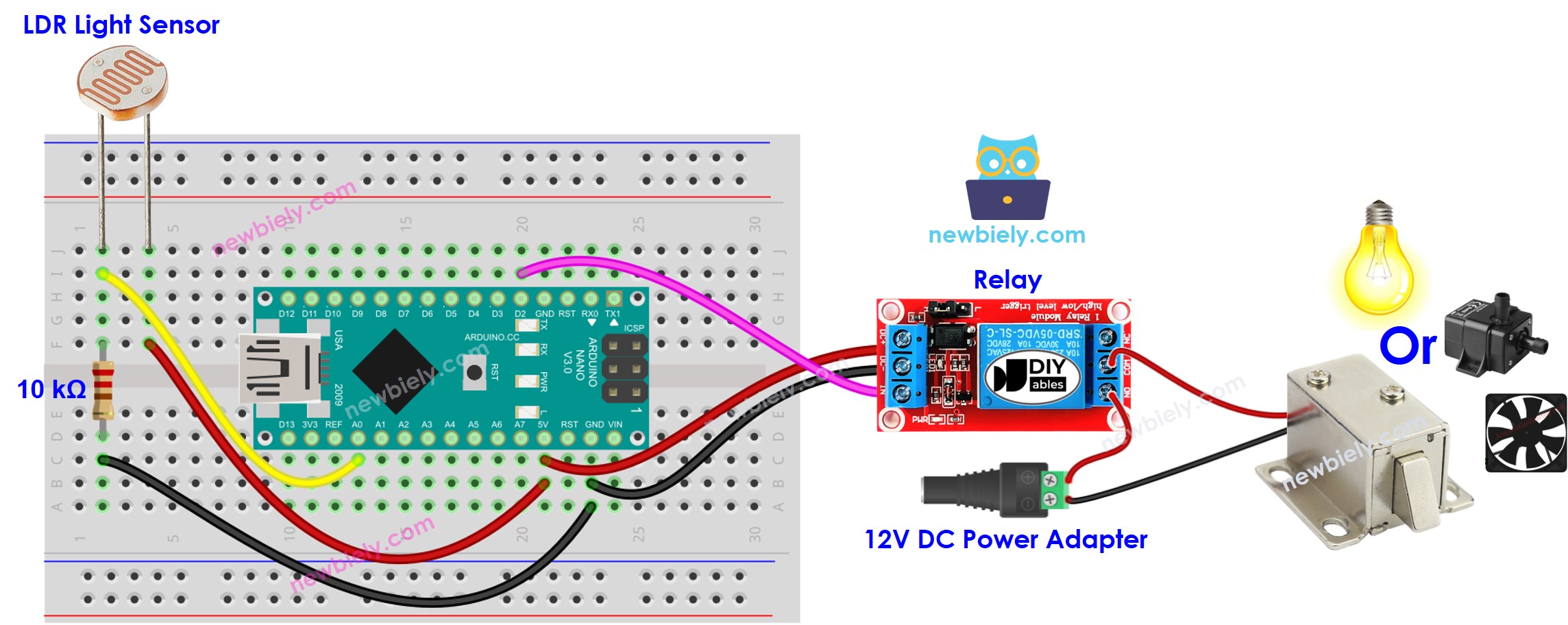
This image is created using Fritzing. Click to enlarge image
See The best way to supply power to the Arduino Nano and other components.
Arduino Nano Code
Detailed Instructions
- Plug the USB cable into both the Arduino Nano and the PC.
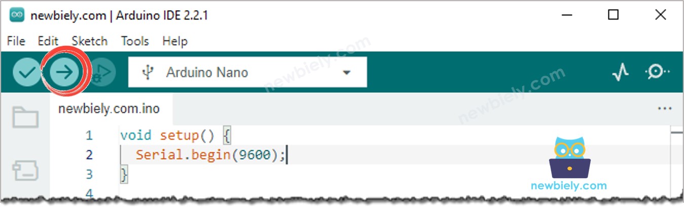
- Launch the Arduino IDE, choose the correct board and port.
- Copy the code and open it in the Arduino IDE.
- Click the Upload button in the Arduino IDE to compile and upload the code to the Arduino Nano.
- Emit light source towards the sensor
- Check out the alteration in the relay's status
Code Explanation
Check out the line-by-line explanation contained in the comments of the source code!