Arduino Nano - DIP Switch
Dual In-line Package (DIP) switches find frequent application in electronics for configuration tasks, like device addresses, communication settings, security codes, operation mode... This tutorial will delve into how to use the DIP switch with Arduino Nano. Specifically, we'll cover:
- Understanding the DIP switch and its working principles.
- Establishing connections between the DIP switch and Arduino Nano.
- Programming Arduino Nano to read the ON/OFF status of the DIP switch.
- Programming Arduino Nano to interpret the integer value set by the DIP switch.
Hardware Preparation
Or you can buy the following kits:
| 1 | × | DIYables Sensor Kit (18 sensors/displays) |
Additionally, some of these links are for products from our own brand, DIYables .
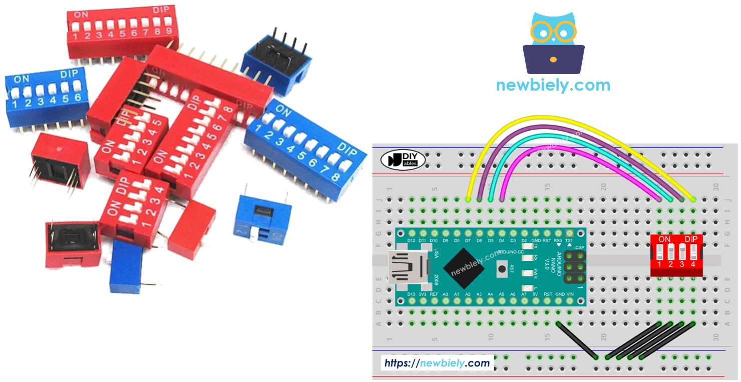
Overview of DIP Switch
DIP switches are primarily utilized for configuring devices, offering users the ability to set parameters like device addresses, communication settings, security codes, operation modes, and system preferences across various industries and applications.
A DIP switch comprises multiple small slide switches bundled together, with each slide switch referred to as a "position". DIP switches are available in various types determined by the number of positions they possess. For example, there are 2-position, 4-position, 5-position, 6-position, 8-position, and 10-position DIP switches.
Each position on a DIP switch represents a configurable bit of a number. By toggling the positions between ON and OFF, we can set the desired numerical value.
Pinout
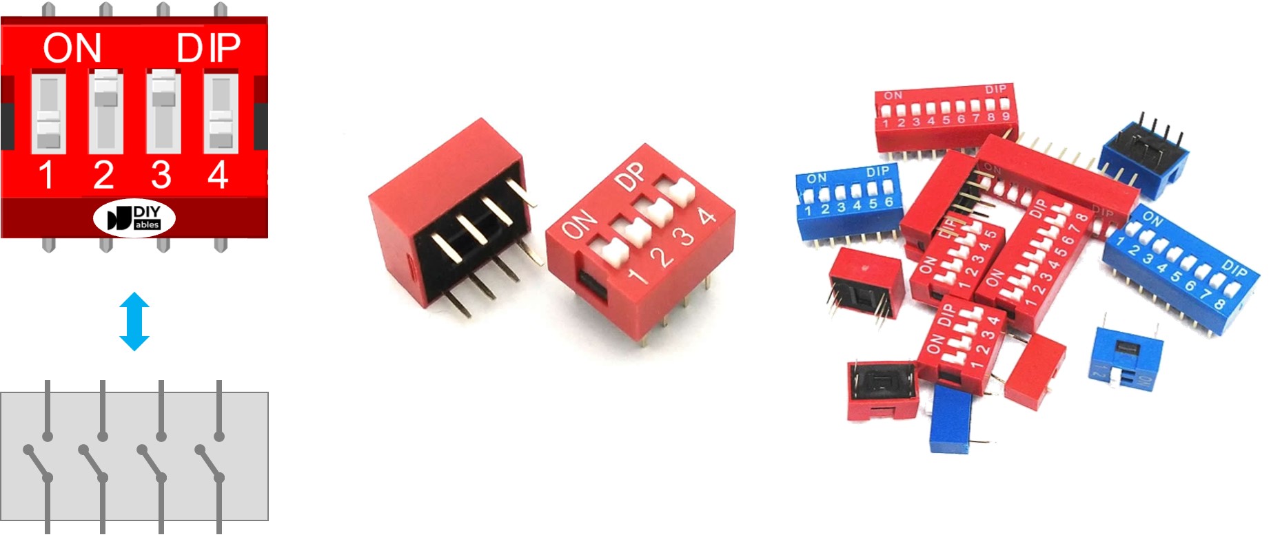
A DIP switch is made up of two rows of pins, where the number of pins in each row matches the available switch positions. For instance, a 4-position DIP switch includes a total of 8 pins, evenly divided with 4 pins on each side. In the assembly of the DIP switch, every set of opposite pins forms a slide switch. It's important to note that differentiating between pins on the two sides is unnecessary as they can be interchanged.
How It Works
In DIP switches, when a switch is in the ON position, it indicates that the switch is engaged or closed. This means an electrical connection is established, enabling current to pass through the switch.
Conversely, when a switch is in the OFF position, it signifies that the switch is disengaged or open. In this state, the electrical connection is disrupted, preventing current from flowing through the switch.
To sum up:
- ON position: Circuit closed, permitting current flow.
- OFF position: Circuit open, blocking current flow.
When we connect one side of a switch to GND and the other side to an Arduino Nano pin, then configure the Arduino Nano pin as a pull-up digital input, the table below demonstrates the relationship between the switch position and the values read from the Arduino Nano:
| DIP switch position | Binary representation | Circuit state | Arduino Nano pin state |
|---|---|---|---|
| ON | 1 | CLOSED | LOW |
| OFF | 0 | OPEN | HIGH |
In the next parts, we will use 4-position DIP switch for example. You can easily to adapt for 2-position DIP switches, 3-position DIP switches, 5-position DIP switches, 6-position DIP switches, 8-position DIP switches, and 10-position DIP switches...
Wiring Diagram
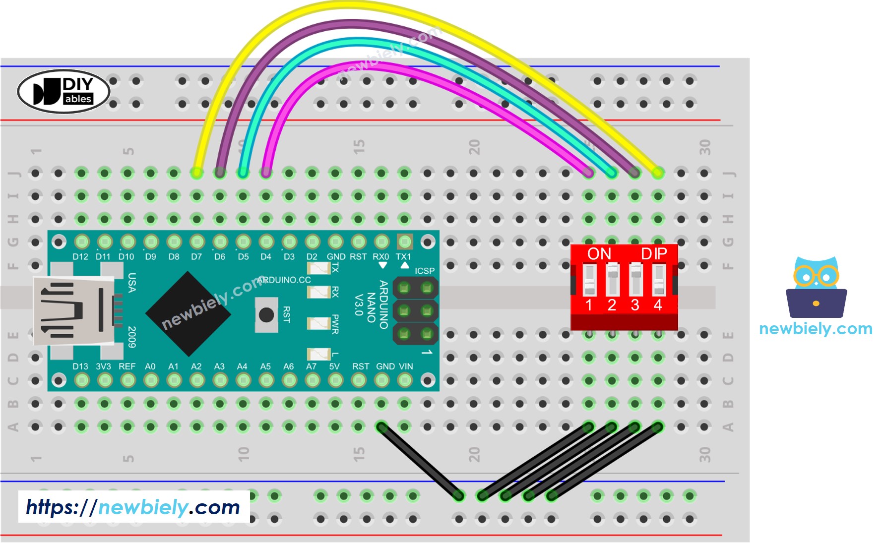
This image is created using Fritzing. Click to enlarge image
See The best way to supply power to the Arduino Nano and other components.
Arduino Nano Code - DIP Switch
We will learn through two pieces of code:
- Reading the ON/OFF state of individual position on the DIP switch.
- Encoding the positions into a number.
Arduino Nano code - Reading the ON/OFF state of the DIP switch
Detailed Instructions
- Do wiring as above wiring diagram
- Connect Arduino Nano to PC via USB cable
- Open Arduino IDE
- Select the right board and port
- Click Upload button on Arduino IDE to upload code to Arduino Nano
- Switch each position on the DIP Switch to ON one by one.
- See the result on Serial Monitor.
Arduino Nano code - Encoding the states of DIP switch into a number
Detailed Instructions
- Upload the above code to Arduino Nano
- Switch each position on the DIP switch to ON one by one.
- See the result on Serial Monitor, it look like below.
Please note that the value depends on positions of each slide switches. The below table shows the mapping between ON/OFF position and the integer value for 4-position DIP switch:
| Position-1 | Position-2 | Position-3 | Position-4 | Binary Value | Decimal Value |
|---|---|---|---|---|---|
| OFF | OFF | OFF | OFF | 0000 | 0 |
| OFF | OFF | OFF | ON | 0001 | 1 |
| OFF | OFF | ON | OFF | 0010 | 2 |
| OFF | OFF | ON | ON | 0011 | 3 |
| OFF | ON | OFF | OFF | 0100 | 4 |
| OFF | ON | OFF | ON | 0101 | 5 |
| OFF | ON | ON | OFF | 0110 | 6 |
| OFF | ON | ON | ON | 0111 | 7 |
| ON | OFF | OFF | OFF | 1000 | 8 |
| ON | OFF | OFF | ON | 1001 | 9 |
| ON | OFF | ON | OFF | 1010 | 10 |
| ON | OFF | ON | ON | 1011 | 11 |
| ON | ON | OFF | OFF | 1100 | 12 |
| ON | ON | OFF | ON | 1101 | 13 |
| ON | ON | ON | OFF | 1110 | 14 |
| ON | ON | ON | ON | 1111 | 15 |