Arduino Nano - Rain Sensor
The rain sensor can detect and measure rain/snow levels, offering both digital (LOW/HIGH) and analog outputs. This tutorial demonstrates using an Arduino Nano to connect and utilize the rain sensor, covering how to read the digital signal for rain detection and the analog signal for measuring rain levels.
Following that, you can customize the code to trigger a motor or warning system upon detecting rain/snow.
Hardware Preparation
Or you can buy the following kits:
| 1 | × | DIYables Sensor Kit (18 sensors/displays) |
Additionally, some of these links are for products from our own brand, DIYables .
Overview of Rain Sensor
The rain sensor can detect rain presence or measure water level from rainfall. It offers two options through a digital output pin and analog output pin.
The rain sensor consists of two parts: sensing pad and electronic module
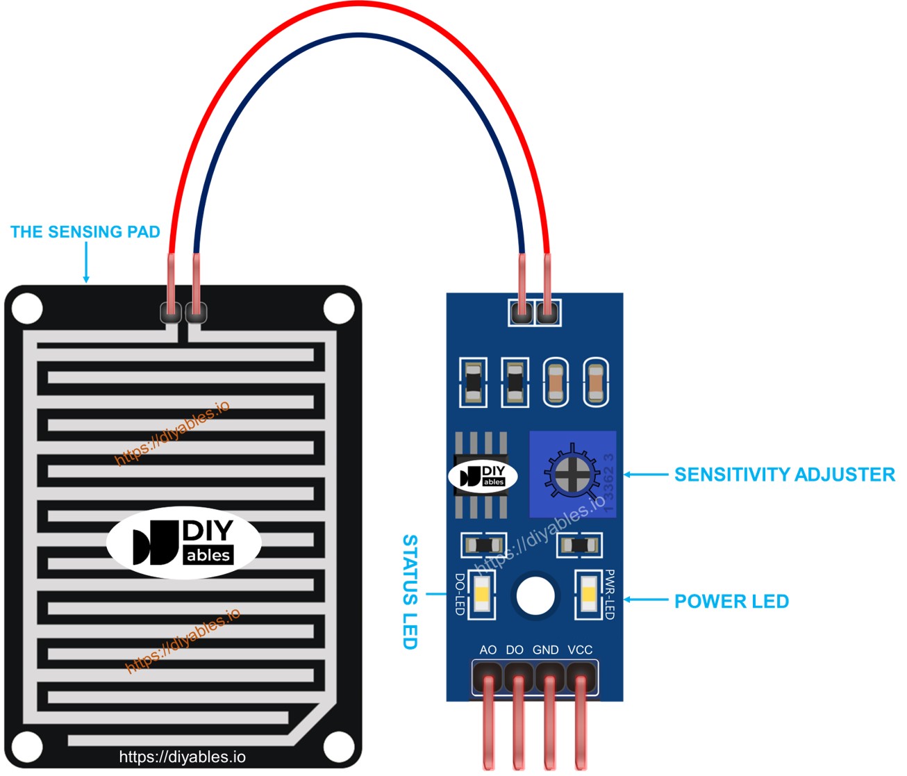
The sensing pad
The sensing pad, positioned outdoors to encounter rain/snow (e.g., on a roof), features exposed copper traces divided into two groups: power traces and sense traces. These traces remain unconnected unless bridged by water or snow. Both power and sense traces are interchangeable, allowing you to designate one as the power trace while the other functions as the sense trace.
The electronic module
The electronic module of the rain sensor transforms signals from the sensing pad into analog or digital values readable by the Arduino Nano. It includes four pins:
- VCC pin: Connects to VCC (3.3V to 5V).
- GND pin: Connects to GND (0V).
- DO pin: Digital output pin. It is HIGH if rain is not detected and LOW if detected. The rain detection threshold is adjustable with a built-in potentiometer.
- AO pin: Analog output pin. The output value decreases with increased water on the sensing pad and increases with decreased water.
Furthermore, it features two LED indicators:
- One PWR-LED indicator for power.
- One DO-LED indicator for the rain state on the DO pin, illuminating when rain is present.
How It Works
Regarding the DO pin:
- The module features a built-in potentiometer for adjusting the threshold (sensitivity).
- When the intensity surpasses the threshold, rain is detected, the sensor's output pin is LOW, and the DO-LED illuminates.
- Conversely, when the intensity is below the threshold, no rain is detected, the output pin is HIGH, and the DO-LED is off.
For the AO pin:
- The AO pin reads lower values as the water content in the sensing pad increases.
- Conversely, it reads higher values as the water content decreases.
It's essential to note that the potentiometer does not influence the AO pin's value.
Wiring Diagram
As highlighted earlier, connecting the VCC pin of the sensor directly to the 3.3V or 5V pins on the Arduino Nano can shorten the sensor's lifespan due to electrochemical corrosion. To mitigate this, it is recommended to connect the VCC pin of the rain sensor to an output pin on the Arduino Nano. This way, the programming of that pin can be configured to power the rain sensor only during readings, minimizing the impact of electrochemical corrosion.
Since the rain sensor module has two outputs, you can choose to use one or both of them, depending on what you need.
- The wiring diagram between Arduino Nano and the rain sensor when using DO only.
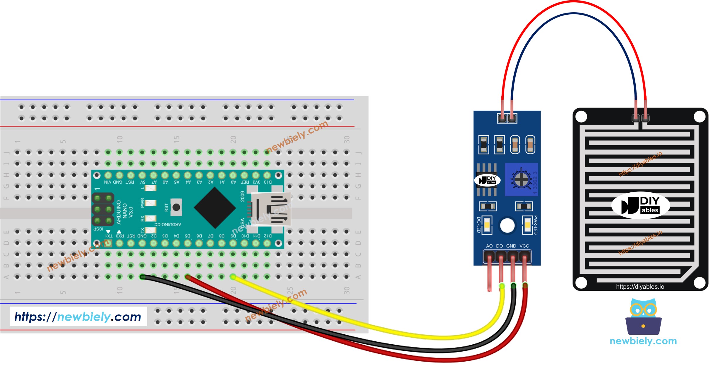
This image is created using Fritzing. Click to enlarge image
- The wiring diagram between Arduino Nano and the rain sensor when using AO only.
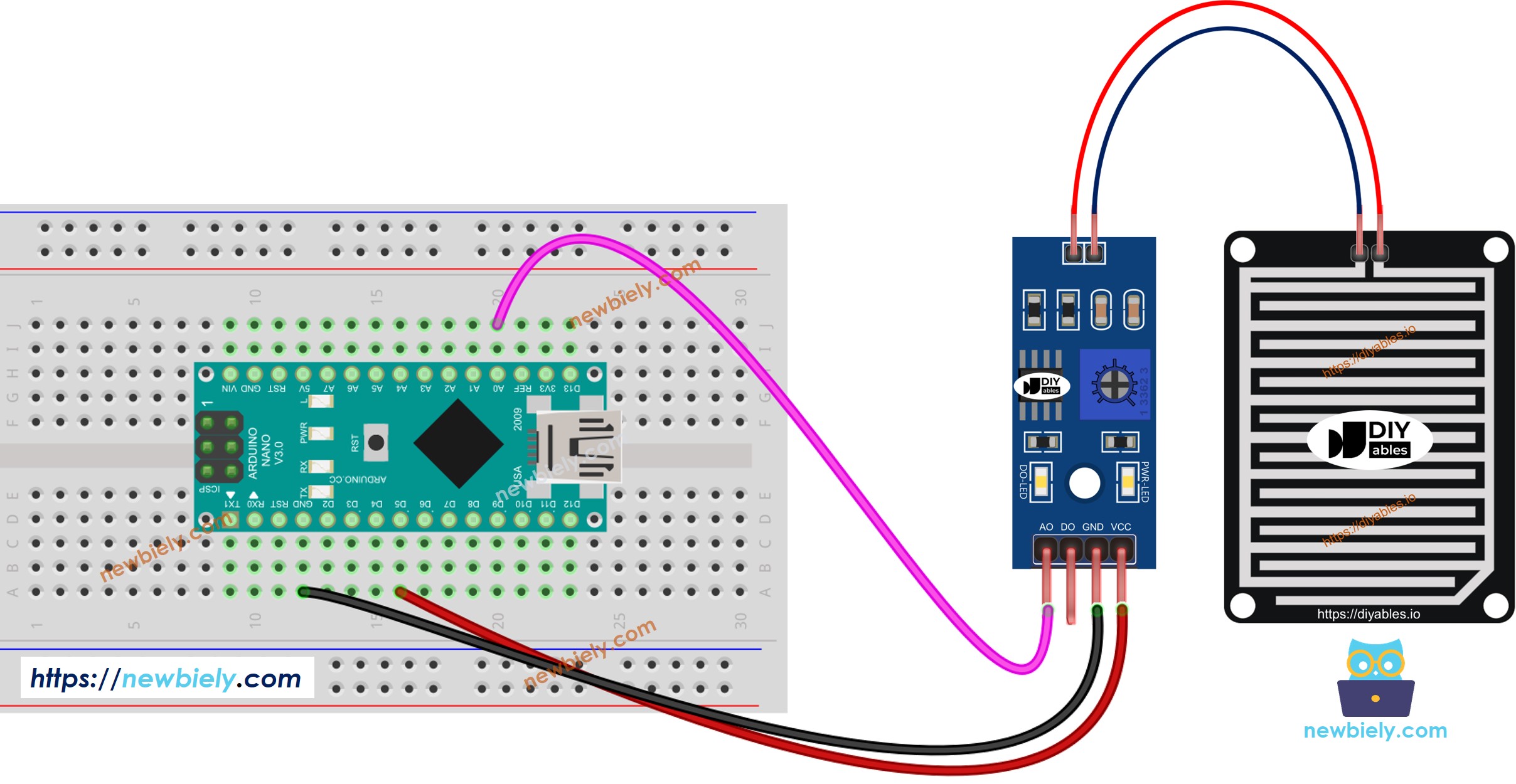
This image is created using Fritzing. Click to enlarge image
- The wiring diagram between Arduino Nano and the rain sensor when using both AO an DO.
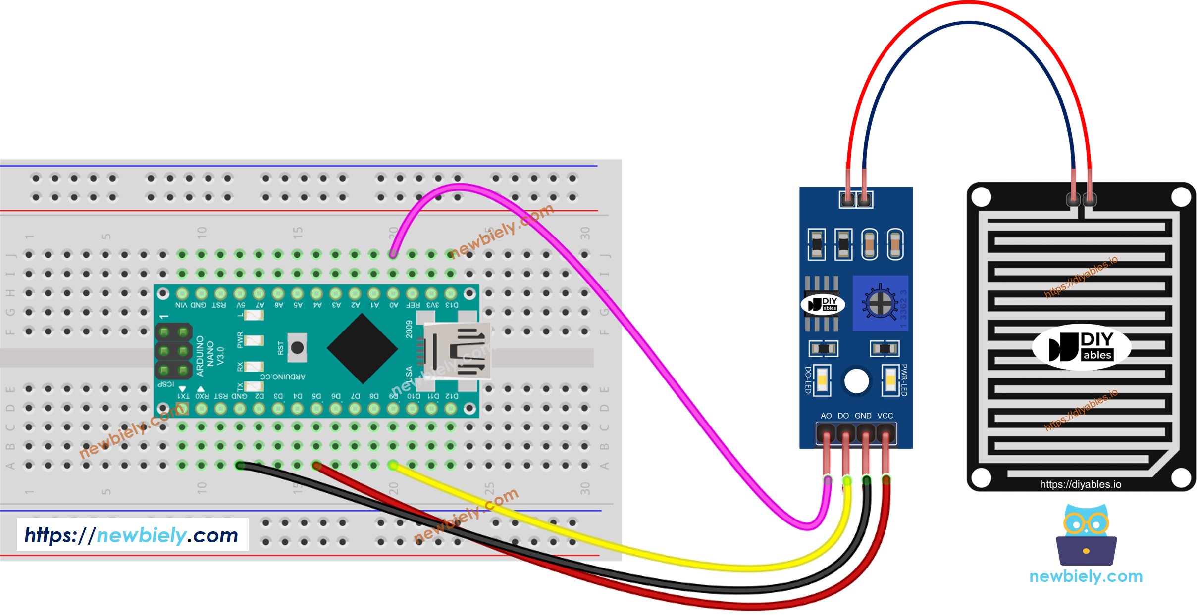
This image is created using Fritzing. Click to enlarge image
See The best way to supply power to the Arduino Nano and other components.
Arduino Nano Code - Read value from DO pin
Detailed Instructions
- Copy the above code and open with Arduino IDE
- Click Upload button on Arduino IDE to upload code to Arduino Nano
- Drop some water to the rain sensor
- Check out the result on the Serial Monitor.
Please keep in mind that if you notice the LED status remaining on constantly or off even when the sensor faces to a rain, you can adjust the potentiometer to fine-tune the sensitivity of the sensor.
Arduino Nano Code - Read value from AO pin
Detailed Instructions
- Copy the above code and open with Arduino IDE
- Click Upload button on Arduino IDE to upload code to Arduino Nano
- Drop some water to the rain sensor
- Check out the result on the Serial Monitor.