Arduino Nano - Door Sensor - Relay

This tutorial instructs you how to use the Arduino Nano and door sensor to control the relay. By connecting the relay to a soleniod lock, light bulb, LED strip, motor, or actuator..., we can use a door sensor to control the them. We will learn two different applications:

Application 1 - The relay is activated when door is open and the relay is deactivated when door is closed. The relay state is synchronized with the door sensor state. In detail:

Application 2 - The relay state is toggled each time the door is opened. More specifically:

Hardware Preparation

1×Arduino Nano
1×USB A to Mini-B USB cable
1×Door Sensor
1×Relay
1×Breadboard
1×Jumper Wires
1×(Optional) Solenoid Lock
1×(Optional) 12V Power Adapter
1×(Optional) DC Power Jack
1×(Optional) 9V Power Adapter for Arduino Nano
1×(Recommended) Screw Terminal Adapter for Arduino Nano

Or you can buy the following sensor kits:

1×DIYables Sensor Kit (30 sensors/displays)
1×DIYables Sensor Kit (18 sensors/displays)
Disclosure: Some of the links provided in this section are Amazon affiliate links. We may receive a commission for any purchases made through these links at no additional cost to you. We appreciate your support.

Overview of Relay and Door Sensor

If you are unfamiliar with relay and door sensor (including pinout, operation, and programming), the following tutorials can help:

Wiring Diagram

The wiring diagram between Arduino Nano and door sensor relay

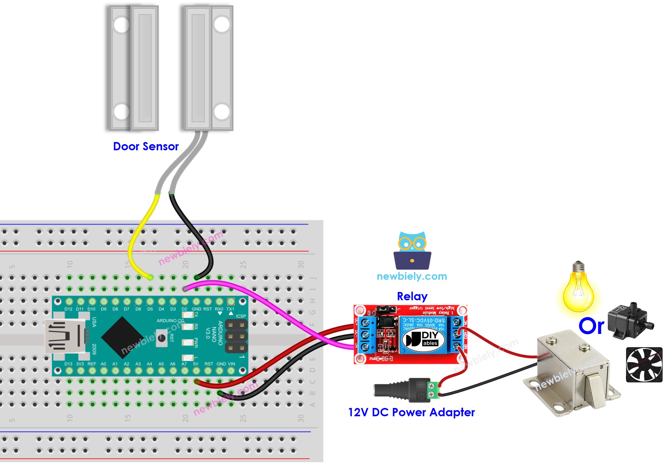
This image is created using Fritzing. Click to enlarge image

Application 1 - The relay state is in sync with the door sensor state

Arduino Nano Code

/* * This Arduino Nano code was developed by newbiely.com * * This Arduino Nano code is made available for public use without any restriction * * For comprehensive instructions and wiring diagrams, please visit: * https://newbiely.com/tutorials/arduino-nano/arduino-nano-door-sensor-relay */ #define DOOR_SENSOR_PIN 5 // The Arduino Nano pin connected to the door sensor's pin #define RELAY_PIN 2 // The Arduino Nano pin connected to the relay module int door_state; void setup() { Serial.begin(9600); // Initialize the Serial to communicate with the Serial Monitor. pinMode(DOOR_SENSOR_PIN, INPUT_PULLUP); // set arduino pin to input pull-up mode pinMode(RELAY_PIN, OUTPUT); // set arduino pin to output mode } void loop() { door_state = digitalRead(DOOR_SENSOR_PIN); // read state if (door_state == HIGH) { Serial.println("The door is open"); digitalWrite(RELAY_PIN, HIGH); // turn on relay } else { Serial.println("The door is closed"); digitalWrite(RELAY_PIN, LOW); // turn off relay } }

Detailed Instructions

  • Connect an Arduino Nano to your computer with a USB cable.
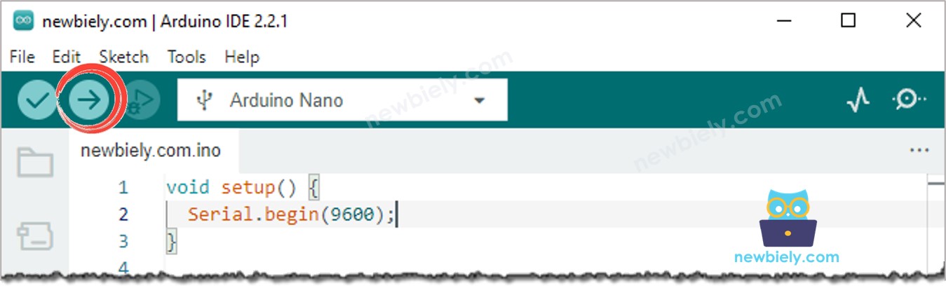
  • Launch the Arduino IDE, and select the correct board and port.
  • Copy the code and open it in the Arduino IDE.
  • Click the Upload button on the Arduino IDE to compile and upload the code to the Arduino Nano.
Arduino IDE Upload Code
  • Open and close the door
  • Check out the change in the relay's condition.

You will see that the relay state is in sync with the door sensor state.

Code Explanation

Check out the line-by-line explanation contained in the comments of the source code!

Application 2 - Door Sensor toggles Relay

Arduino Nano Code - Door Sensor toggles Relay

/* * This Arduino Nano code was developed by newbiely.com * * This Arduino Nano code is made available for public use without any restriction * * For comprehensive instructions and wiring diagrams, please visit: * https://newbiely.com/tutorials/arduino-nano/arduino-nano-door-sensor-relay */ #define DOOR_SENSOR_PIN 5 // The Arduino Nano pin connected to the door sensor's pin #define RELAY_PIN 2 // The Arduino Nano pin connected to the relay module int relay_state = LOW; // The current state of relay int prev_door_state; // The previous state of door sensor int door_state; // The current state of door sensor void setup() { Serial.begin(9600); // Initialize the Serial to communicate with the Serial Monitor. pinMode(DOOR_SENSOR_PIN, INPUT_PULLUP); // set arduino pin to input pull-up mode pinMode(RELAY_PIN, OUTPUT); // set arduino pin to output mode door_state = digitalRead(DOOR_SENSOR_PIN); } void loop() { prev_door_state = door_state; // save the last state door_state = digitalRead(DOOR_SENSOR_PIN); // read new state if (prev_door_state == HIGH && door_state == LOW) { // state change: HIGH -> LOW Serial.println("The door-closing event is detected"); // toggle state of relay relay_state = !relay_state; // control relay according to the toggled state digitalWrite(RELAY_PIN, relay_state); } }

Code Explanation

You can locate the explanation in the comment lines of the Arduino Nano code above.

In the code, the expression relay_state = !relay_state is equivalent to the following code:

if(relay_state == LOW) relay_state = HIGH; else relay_state = LOW;

Detailed Instructions

  • Copy the code and open it in the Arduino IDE.
  • Upload the code to the Arduino Nano.
  • Open and close the door several times.
  • Check out the change in the relay's state.

You'll notice that the relay will switch on or off one time whenever you close the door.

Video Tutorial

※ OUR MESSAGES

  • As freelancers, We are AVAILABLE for HIRE. See how to outsource your project to us
  • Please feel free to share the link of this tutorial. However, Please do not use our content on any other websites. We invested a lot of effort and time to create the content, please respect our work!