Arduino Nano - Feedback Actuator

with feedback

In a prior tutorial, we discussed the linear actuator without feedback. Now, we will be exploring the feedback linear actuator (also known as the feedback linear actuator). This type of actuator provides information to determine the position of its stroke and then control it. Specifically, we will be looking at:

Hardware Preparation

1×Arduino Nano
1×USB A to Mini-B USB cable
1×12V Linear Feedback Actuator
1×L298N Motor Driver Module
1×12V Power Adapter
1×DC Power Jack
1×Jumper Wires
1×(Optional) 9V Power Adapter for Arduino Nano
1×(Recommended) Screw Terminal Adapter for Arduino Nano

Or you can buy the following sensor kits:

1×DIYables Sensor Kit (30 sensors/displays)
1×DIYables Sensor Kit (18 sensors/displays)
Disclosure: Some of the links provided in this section are Amazon affiliate links. We may receive a commission for any purchases made through these links at no additional cost to you. We appreciate your support.

Overview of Feedback Linear Actuator

A linear actuator with feedback is available, which provides a signal to identify its position and control it. This feedback is in the form of a potentiometer that outputs a voltage value that is proportional to the stroke's position.

Feedback Linear Actuator Pinout

A Feedback Linear Actuator has 5 wires:

  • Actuator Positive wire: This wire is used to control the linear actuator by utilizing high voltage (12V, 24V, 48V...).
  • Actuator Negative wire: This wire is used to control the linear actuator by utilizing high voltage (12V, 24V, 48V...).
  • 5V wire: this wire is used for the feedback potentiometer. Connect this wire to 5V or 3.3V
  • GND wire: this wire is used for the feedback potentiometer. Connect this wire to GND
  • Potentiometer wire: (also called feedback wire, or output wire) this wire outputs the voltage value in proportion to the stroke's position.
Feedback Linear Actuator pinout

How It Works

If we supply high voltage to the positive and negative wires, the stroke of the actuator will be extended or retracted. Specifically:

  • If 12V (12V, 24V, 48V...) is connected to the positive wire and GND to the negative wire, the linear actuator will extend at full speed until it reaches the limit.
  • If 12V (12V, 24V, 48V...) is connected to the negative wire and GND to the positive wire, the linear actuator will retract at full speed until it reaches the limit.
  • If power is stopped to the actuator (GND to both positive and negative wire), the actuator will cease extending/retracting.

※ NOTE THAT:

  • The voltage necessary for operating the actuator is determined by its specifications. To find out the exact voltage value, consult the datasheet or manual.
  • Even when power is cut off, the actuator can maintain its position while carrying a load.

The voltage in the potentiometer wire is related to the stroke's position on the actuator. By measuring this voltage, we can determine the stroke's position.

Wiring Diagram

Take out all three jumpers from the L298N module prior to connecting the wires.

The wiring diagram between Arduino Nano and Linear Actuator L298N Driver

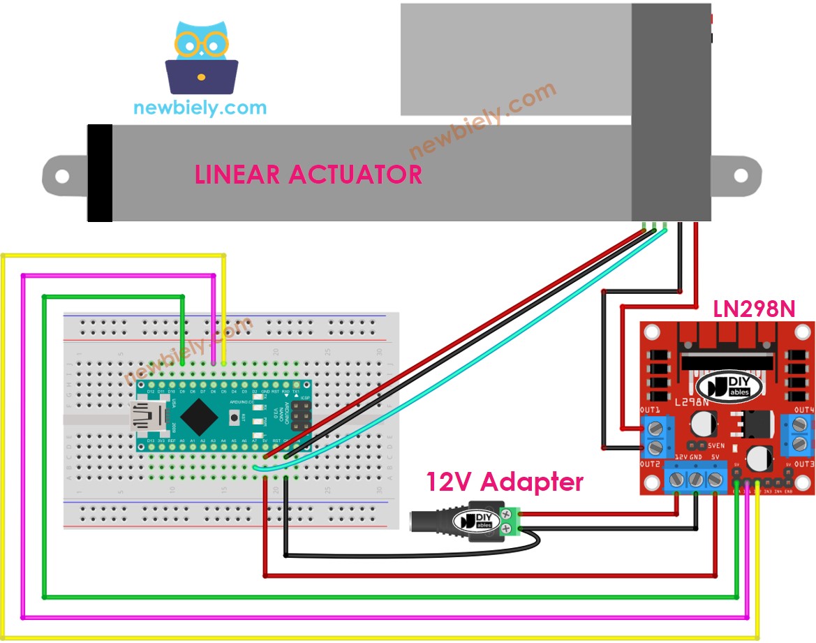
This image is created using Fritzing. Click to enlarge image

How to control extend/retract a linear actuator

Check out the tutorial on Arduino Nano - Actuator at BASE_URL/tutorials/arduino-nano/arduino-nano-actuator.

How to find the position of the linear actuator

This is an example of how to locate the stroke on a linear actuator. It provides an illustration of the process.

Calibration

  • Determine the length of the actuator's stroke (in millimeters) by either measuring it with a ruler or consulting the datasheet.
  • Run the following code to determine the output values when the linear actuator is fully extended and fully retracted.
/* * This Arduino Nano code was developed by newbiely.com * * This Arduino Nano code is made available for public use without any restriction * * For comprehensive instructions and wiring diagrams, please visit: * https://newbiely.com/tutorials/arduino-nano/arduino-nano-feedback-actuator */ // The code for getting the feedback when the actuator fully extended and retracted #define ENA_PIN 7 // The Arduino Nano pin connected to the EN1 pin L298N #define IN1_PIN 6 // The Arduino Nano pin connected to the IN1 pin L298N #define IN2_PIN 5 // The Arduino Nano pin connected to the IN2 pin L298N #define POTENTIOMETER_PIN A0 // The Arduino Nano pin connected to the potentiometer of the actuator void setup() { Serial.begin(9600); // initialize digital pins as outputs. pinMode(ENA_PIN, OUTPUT); pinMode(IN1_PIN, OUTPUT); pinMode(IN2_PIN, OUTPUT); digitalWrite(ENA_PIN, HIGH); } void loop() { // extend the actuator digitalWrite(IN1_PIN, HIGH); digitalWrite(IN2_PIN, LOW); delay(20000); // wait for actuator fully extends. It will stop extending automatically when reaching the limit // read the analog in value: int POTENTIOMETER_MAX = analogRead(POTENTIOMETER_PIN); Serial.print("POTENTIOMETER_MAX = "); Serial.println(POTENTIOMETER_MAX); // retracts the actuator digitalWrite(IN1_PIN, LOW); digitalWrite(IN2_PIN, HIGH); delay(20000); // wait for actuator fully extends. It will stop retracting automatically when reaching the limit int POTENTIOMETER_MIN = analogRead(POTENTIOMETER_PIN); Serial.print("POTENTIOMETER_MIN = "); Serial.println(POTENTIOMETER_MIN); }
  • Observe the log on the Serial Monitor as demonstrated in the example below.
COM6
Send
POTENTIOMETER_MAX = 987 POTENTIOMETER_MIN = 13
Autoscroll Show timestamp
Clear output
9600 baud  
Newline  

Make a note of the following three values and update them in the code below: the minimum value, the maximum value, and IN1_PIN and IN2_PIN. If the minimum and maximum values are swapped, also swap IN1_PIN and IN2_PIN.

Arduino Nano code that calculate the position of the actuator

/* * This Arduino Nano code was developed by newbiely.com * * This Arduino Nano code is made available for public use without any restriction * * For comprehensive instructions and wiring diagrams, please visit: * https://newbiely.com/tutorials/arduino-nano/arduino-nano-feedback-actuator */ #define ENA_PIN 7 // The Arduino Nano pin connected to the EN1 pin L298N #define IN1_PIN 6 // The Arduino Nano pin connected to the IN1 pin L298N #define IN2_PIN 5 // The Arduino Nano pin connected to the IN2 pin L298N #define POTENTIOMETER_PIN A0 // The Arduino Nano pin connected to the potentiometer of the actuator #define STROKE_LENGTH 102 // PLEASE UPDATE THIS VALUE (in millimeter) #define POTENTIOMETER_MAX 987 // PLEASE UPDATE THIS VALUE #define POTENTIOMETER_MIN 13 // PLEASE UPDATE THIS VALUE void setup() { Serial.begin(9600); // initialize digital pins as outputs. pinMode(ENA_PIN, OUTPUT); pinMode(IN1_PIN, OUTPUT); pinMode(IN2_PIN, OUTPUT); digitalWrite(ENA_PIN, HIGH); } void loop() { // extend the actuator digitalWrite(IN1_PIN, HIGH); digitalWrite(IN2_PIN, LOW); int potentiometer_value = analogRead(POTENTIOMETER_PIN); int stroke_pos = map(potentiometer_value, POTENTIOMETER_MIN, POTENTIOMETER_MAX, 0, STROKE_LENGTH); Serial.print("The stroke's position = "); Serial.print(stroke_pos); Serial.println(" mm"); }
  • Refresh the three calibrated values in the code
  • Transfer the code to Arduino Nano
  • Check the outcome on Serial Monitor
COM6
Send
The stroke's position = 2 mm The stroke's position = 35 mm The stroke's position = 43 mm The stroke's position = 60 mm The stroke's position = 68 mm The stroke's position = 79 mm The stroke's position = 83 mm The stroke's position = 96 mm The stroke's position = 100 mm
Autoscroll Show timestamp
Clear output
9600 baud  
Newline  

How to control a linear actuator to a specific position

/* * This Arduino Nano code was developed by newbiely.com * * This Arduino Nano code is made available for public use without any restriction * * For comprehensive instructions and wiring diagrams, please visit: * https://newbiely.com/tutorials/arduino-nano/arduino-nano-feedback-actuator */ #define ENA_PIN 7 // The Arduino Nano pin connected to the EN1 pin L298N #define IN1_PIN 6 // The Arduino Nano pin connected to the IN1 pin L298N #define IN2_PIN 5 // The Arduino Nano pin connected to the IN2 pin L298N #define POTENTIOMETER_PIN A0 // The Arduino Nano pin connected to the potentiometer of the actuator #define STROKE_LENGTH 102 // PLEASE UPDATE THIS VALUE (in millimeter) #define POTENTIOMETER_MAX 987 // PLEASE UPDATE THIS VALUE #define POTENTIOMETER_MIN 13 // PLEASE UPDATE THIS VALUE #define TOLERANCE 5 // in millimeter int targetPosition_mm = 50; // in millimeter void setup() { Serial.begin(9600); // initialize digital pins as outputs. pinMode(ENA_PIN, OUTPUT); pinMode(IN1_PIN, OUTPUT); pinMode(IN2_PIN, OUTPUT); digitalWrite(ENA_PIN, HIGH); } void loop() { int potentiometer_value = analogRead(POTENTIOMETER_PIN); int stroke_pos = map(potentiometer_value, POTENTIOMETER_MIN, POTENTIOMETER_MAX, 0, STROKE_LENGTH); Serial.print("The stroke's position = "); Serial.print(stroke_pos); Serial.println(" mm"); if (stroke_pos < (targetPosition_mm - TOLERANCE)) ACTUATOR_extend(); else if (stroke_pos > (targetPosition_mm + TOLERANCE)) ACTUATOR_retract(); else ACTUATOR_stop(); } void ACTUATOR_extend() { digitalWrite(IN1_PIN, HIGH); digitalWrite(IN2_PIN, LOW); } void ACTUATOR_retract() { digitalWrite(IN1_PIN, LOW); digitalWrite(IN2_PIN, HIGH); } void ACTUATOR_stop() { digitalWrite(IN1_PIN, LOW); digitalWrite(IN2_PIN, LOW); }

Video Tutorial

※ OUR MESSAGES

  • As freelancers, We are AVAILABLE for HIRE. See how to outsource your project to us
  • Please feel free to share the link of this tutorial. However, Please do not use our content on any other websites. We invested a lot of effort and time to create the content, please respect our work!