Arduino Nano - Keypad Door Lock
This tutorial instructs you how to build a password-protected door lock system by using Arduino Nano, keypad, solenoid lock or electromagnetic lock, and LCD display. The below is how the door lock system will work:
- Users will enter a password using the keypad.
- The Arduino Nano will check if the password is correct.
- If the entered password is correct, the Arduino Nano will deactivate the solenoid lock to unlock the door. The door will remain unlocked for a set amount of time (e.g. 20 seconds) before automatically locking again.
To make it easy, the tutorial is divided into multiple steps, from easy to difficult:
- Part 1: A simple keypad door lock system with Arduino Nano, keypad, solenoid lock or electromagnetic lock.
- Part 2: (Optionally) Adding multiple password supports
- Part 3: (Optionally) Adding LCD display to the keypad door lock.
- Part 4: (Optionally) Adding the beep sound when the keypad is pressed.
- Part 5: (Optionally) Adding a door sensor to the keypad door lock.
- Part 6: (Optionally) Managing and storing the valid passwords to the internal EEPROM of Arduino Nano
- Part 7: (Optionally) Saving the access history to SD Card
Hardware Preparation
Or you can buy the following kits:
| 1 | × | DIYables Sensor Kit (18 sensors/displays) |
Additionally, some of these links are for products from our own brand, DIYables .
Buy Note: Alternatively, you can assemble the LCD I2C display using LCD 1602 Display and PCF8574 I2C Adapter Module.
Overview of Keypad, Solenoid Lock, Electromagnetic Lock, and LCD display
Both the solenoid lock and electromagnetic lock are used to lock/unlock the door. They primarily differ from each other in term of machanical design. Their wiring to Arduino Nano are similar. The Arduino Nano code for controlling them are the same.
If you are unfamiliar with keypad, solenoid lock, electromagnetic lock, and LCD display (pinout, how it works, how to program ...), the following tutorials can help you learn:
Wiring Diagram
- Wiring Diagram with Arduino Nano, keypad and solenoid lock
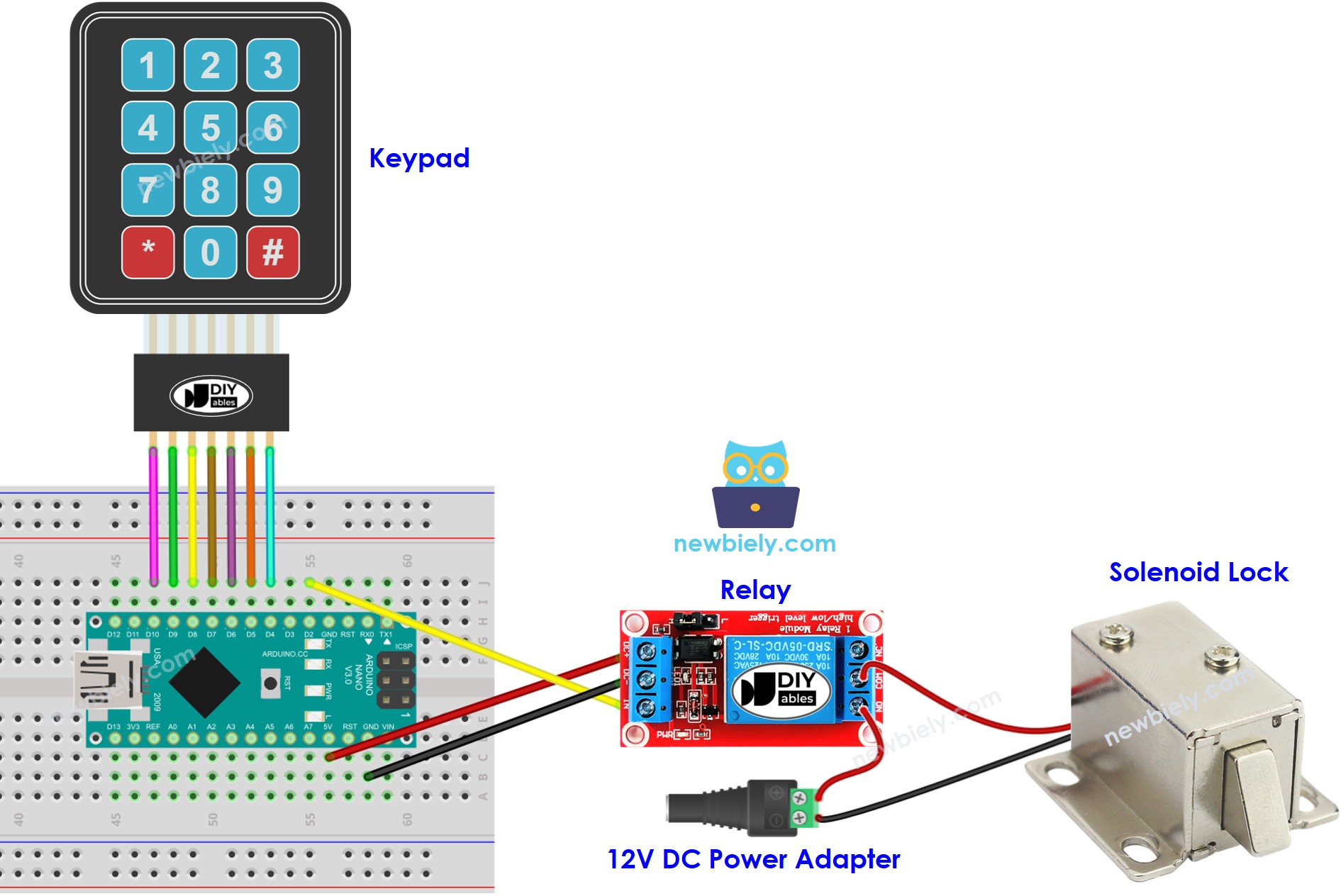
This image is created using Fritzing. Click to enlarge image
- Wiring Diagram with Arduino Nano, keypad and electromagnetic lock
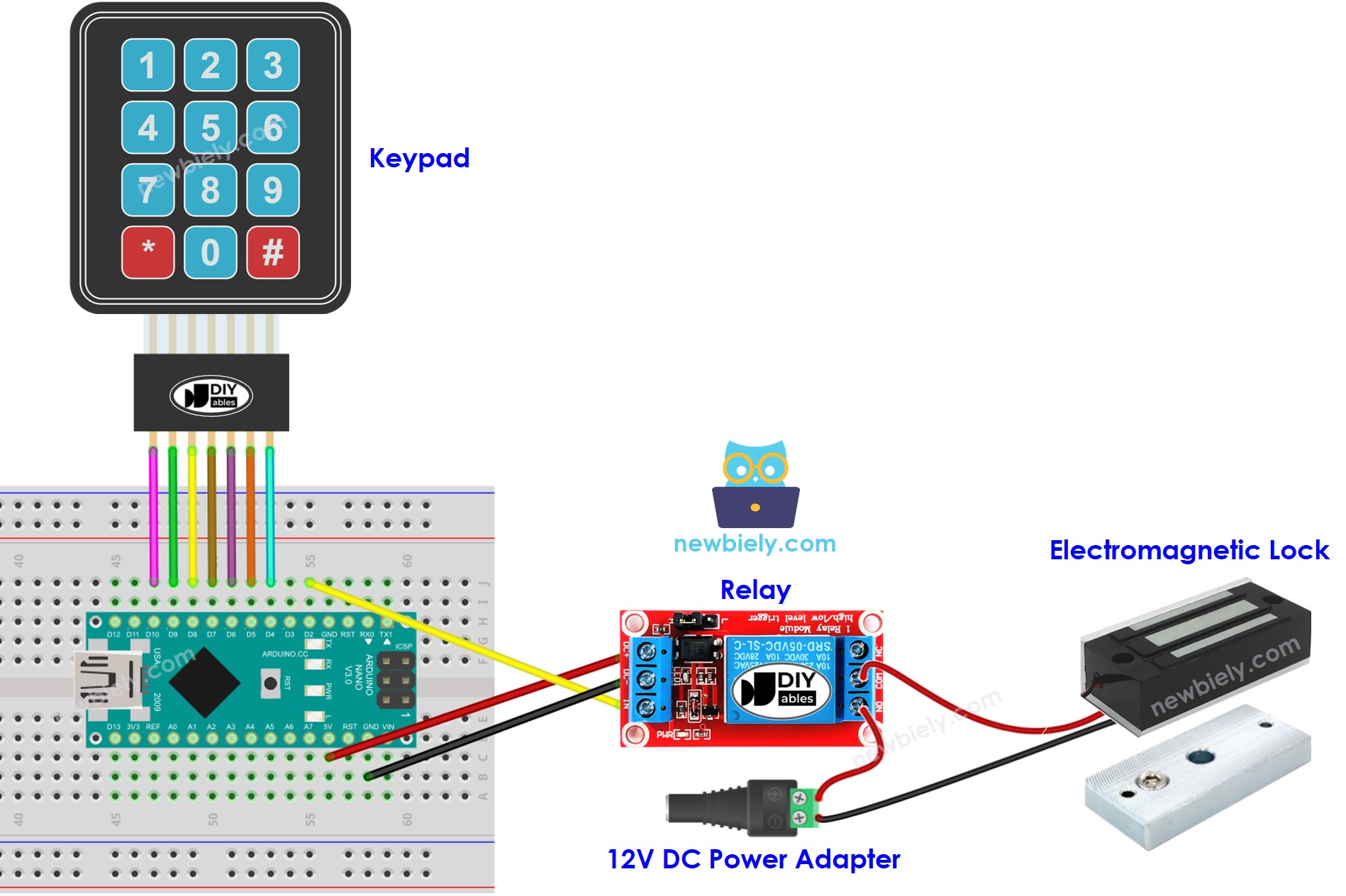
This image is created using Fritzing. Click to enlarge image
Arduino Nano Code - Keypad Door Lock
※ NOTE THAT:
The address of the LCD may differ depending on the manufacturer. In our code, we used 0x27 as specified by DIYables.
Detailed Instructions
- Connect a USB cable to the Arduino Nano and PC.
- Open the Arduino IDE and select the appropriate board and port.
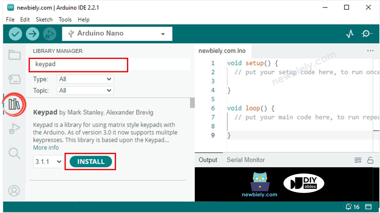
- Click to the Libraries icon on the left bar of the Arduino IDE.
- Search for “keypad”, then locate the keypad library created by Mark Stanley and Alexander Brevig.
- Press the Install button to install the keypad library.
- Copy the code above and open it with the Arduino IDE.
- Click the Upload button to upload the code to the Arduino Nano.
- Open the Serial Monitor.
- Press the 12345 keys followed by the # symbol.
- Then press the 1234 keys followed by the # symbol.
- Check out the lock tongue's state for 20 seconds.
- Check out the result on the Serial Monitor.
Code Explanation
The valid passwords are pre-defined in the Arduino Nano code. A string is utilized to store the password entered by users, referred to as input string. On the keypad, two keys (* and #) are used for special purposes: to clear the password and to terminate the password. The system works as follows:
- Except for the two special keys, if any other key is pressed, it is added to the input string.
- If * is pressed, the input string is cleared. This can be used to start or restart the input of the password.
- If # is pressed:
- Arduino Nano compares the input string with the pre-defined passwords. If it matches one of the pre-defined passwords, Arduino Nano controls the relay to unlock the door.
- Regardless of whether the password is correct or not, Arduino Nano clears the input string for the next input.
Arduino Nano Code - Multiple Keys
Adding LCD Display to the RFID Door Lock
We can optionally add a LCD display to show the status (e.g. GRANTED/DENIED) to users.
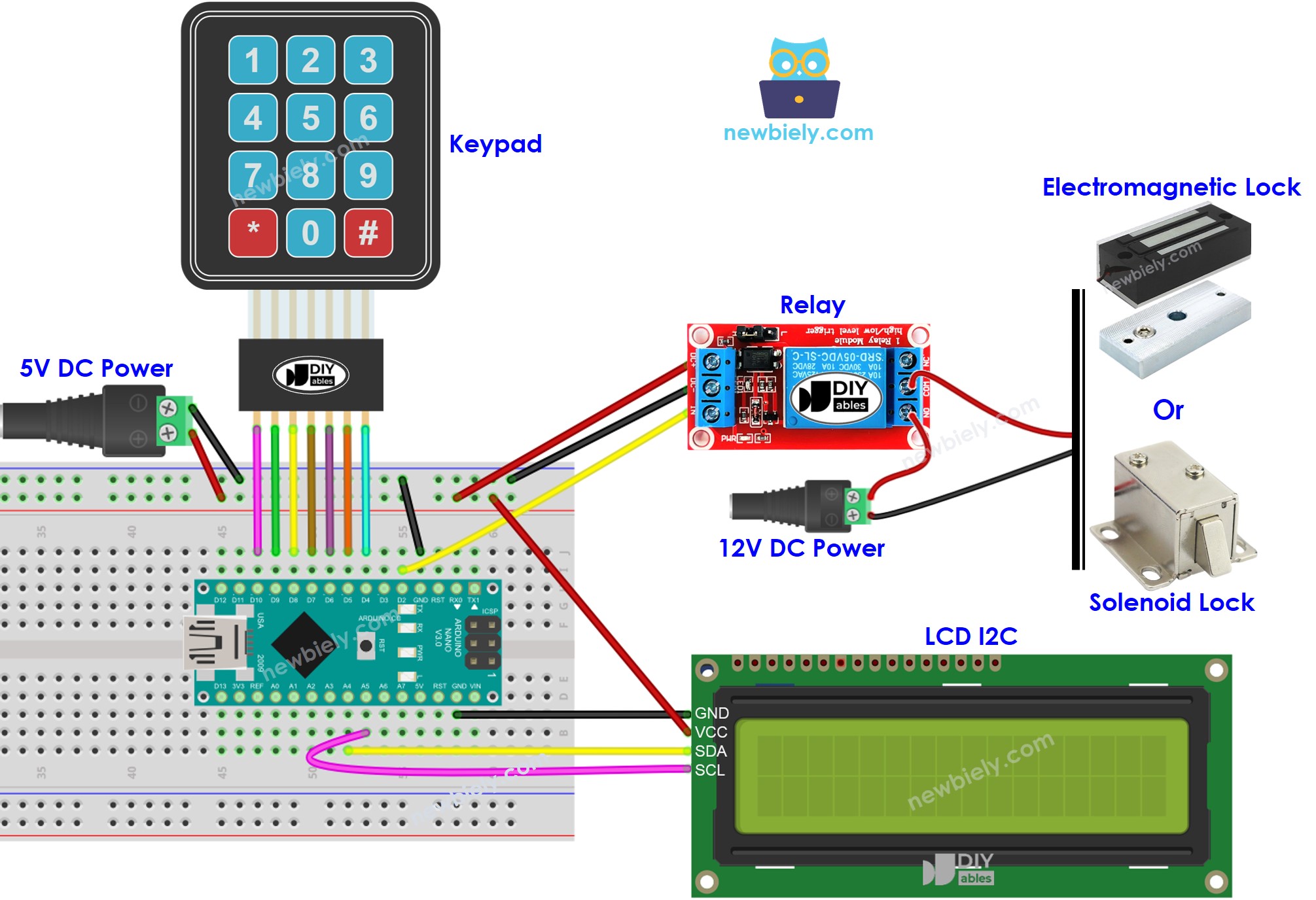
Wiring diagram - Door lock system using keypad, solenoid lock or electromagnetic lock, and LCD display
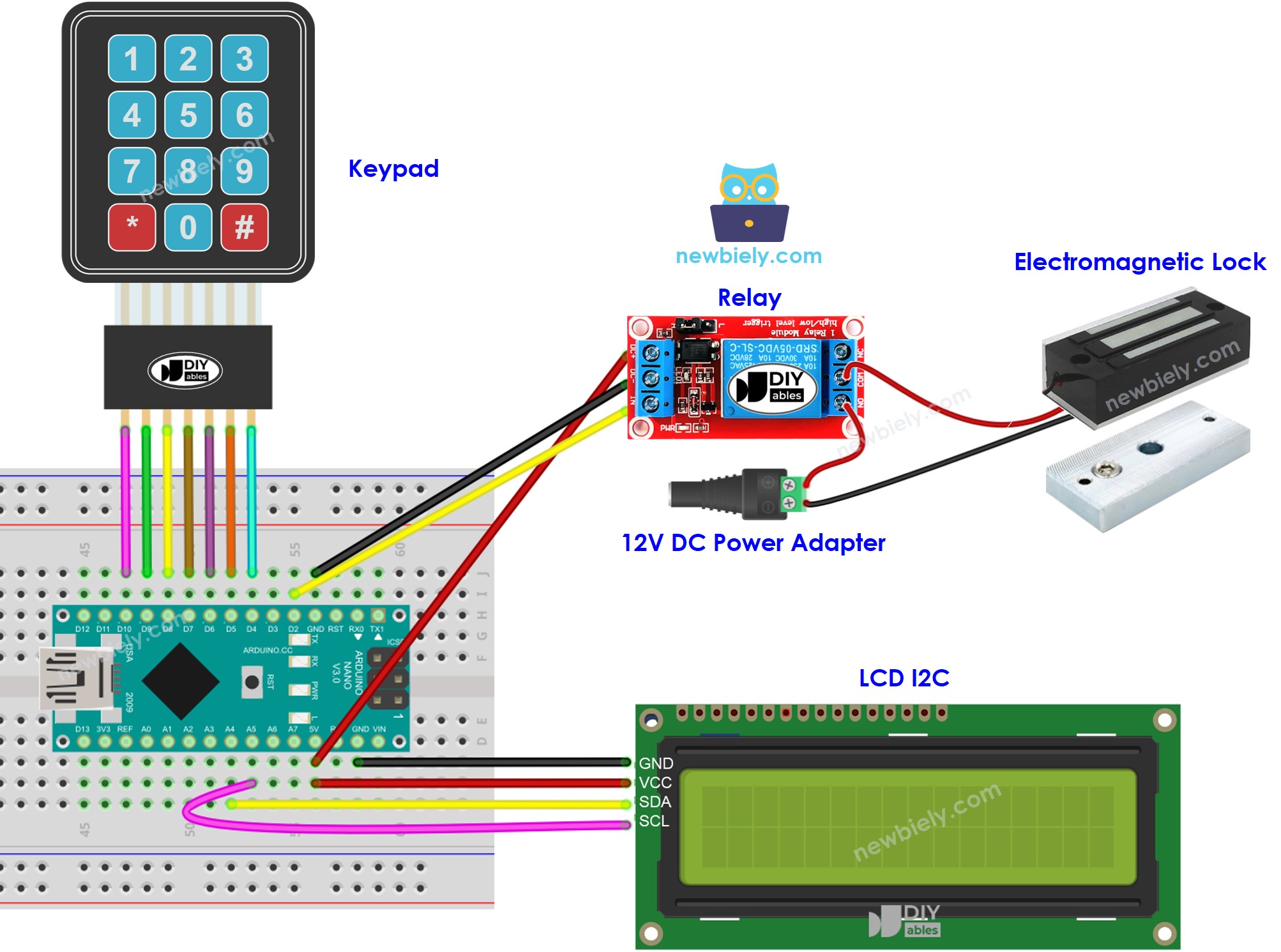
This image is created using Fritzing. Click to enlarge image
Please note that, in the above wiring diagram, both relay and LCD may not works or work unstable due to insufficient power. We strongly advise to use an external power source for both the relay and LCD. Please refer to the following wiring diagram for guidance:
This image is created using Fritzing. Click to enlarge image
See The best way to supply power to the Arduino Nano and other components.
Arduino Nano Code - Keypad Door Lock
※ NOTE THAT:
The address of the LCD can differ depending on the manufacturer. We used 0x27 in our code, as specified by DIYables.
Adding the beep sound when the keypad is pressed.
We can make the door lock look responsive by adding a piezo buzzer to generate a short beep each time a key on keypad is pressed.
It is quite simple to add it. So, we're leaving this part up to your creativity. You can check out the Arduino Nano - Keypad Beep tutorial for more guidance.
Adding a door sensor to the keypad door lock
In the previously mentioned code, the Arduino Nano locks the door after a timeout since unlocking. However, in practical applications, a door sensor is usually added to the system. If the Arduino Nano detects that the door is closed, it locks the door immediately instead of waiting for the timeout.
To avoid overwhelming you, we didn't include the door sensor in the wiring diagram and code. Instead, we're leaving this part up to your creativity. You can check out the Arduino Nano - Door Sensor and Arduino Nano - Door Sensor control Relay tutorials for more guidance.
Managing and storing the valid passwords to EEPROM
The above code has valid passwords (UID) that are hardcoded into the Arduino Nano code. This means that if you want to add or remove passwords, you have to make changes to the code and upload it to the Arduino Nano again, which is inconvenient.
In real-life applications, it's necessary to manage passwords without having to modify and upload the code every time. To achieve this, the passwords can be stored in EEPROM instead of being hardcoded. Consequently, a method is needed to easily manage the passwords from the EEPROM.
Two methods are available for managing passwords in EEPROM:
- Use master passwords
- By utilizing a password as an ADD master password, new passwords can be added to the system. Once the Arduino Nano detects the ADD master password, it switches between the ADD mode and OPERATION mode.
- During the ADD mode, the Arduino Nano adds any new passwords it detects to the EEPROM.
- A similar approach is used for DELETE master password and DELETE mode.
- Use a ADD/DELETE commands via Serial/Bluetooth/IR
- Commands are transmitted via Serial/Bluetooth/IR, utilizing tools such as the Serial Monitor, Bluetooth app, or IR controller.
- The commands consist of a directive (ADD/DELETE) and the password.
In order to utilize any of two above methods, a considerable amount of Arduino Nano code must be added. For individuals who are new to programming, this can be a challenging task. As a result, this tutorial aims to provide a basic understanding of the door lock system without overwhelming beginners with complex code. If you wish to implement this system for practical purposes, please contact us through our paid programming service
Storing the access history to SD Card
To keep track of access history, it might be necessary to save access status (GRANTED/DENIED), and date and time. Since EEPROM has insufficient capacity to store the entire history, an SD card can be used instead. You can find guidance on this Arduino Nano - Log Data with Timestamp to SD Card tutorial.