Arduino Nano - Light Sensor
This tutorial instructs you how to use the light sensor with Arduino Nano. In detail:
- How a light sensor works
- How to connect the light sensor to an Arduino Nano
- How to program the Arduino Nano to read the value from the light sensor
Hardware Preparation
Or you can buy the following kits:
| 1 | × | DIYables Sensor Kit (18 sensors/displays) |
Additionally, some of these links are for products from our own brand, DIYables .
The LDR light sensor is very affordable, but it requires a resistor for wiring, which can make the setup more complex. To simplify the wiring, you can use an LDR light sensor module as an alternative.
Overview of Light Sensor
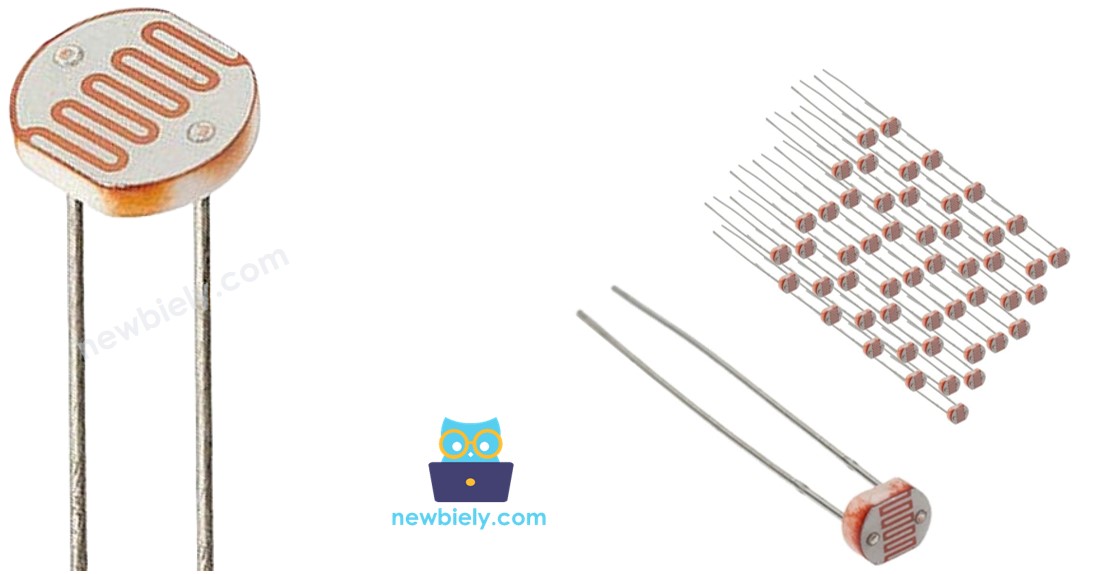
The light sensor used in this tutorial is a photoresistor, also known as a photocell, light-dependent resistor, or LDR.
It is not only used to detect light, but also to measure the amount of brightness or illumination of the surrounding light.
The Light Sensor Pinout
A photoresistor has two pins which do not need to be distinguished as it is a type of resistor and they are symmetrical.
How It Works
The amount of light that the photoresistor's face is exposed to will determine its resistance. By measuring this resistance, we can measure the brightness of the ambient light.
WARNING
The value of the light sensor only gives an indication of the intensity of light, and is not an exact measure of luminous flux. Therefore, it should only be used in applications that do not need a high degree of precision.
Arduino Nano - Light Sensor
Arduino Nano's pins A0 through A7 can be used as analog inputs. These analog input pins convert the voltage (ranging from 0 volts to VCC) into integer values (from 0 to 1023), referred to as ADC value or analog value.
Connect one pin of the photoresistor to an analog input pin. Using analogRead() function, read the analog value from the pin. This will allow us to determine the light levels relatively.
Wiring Diagram
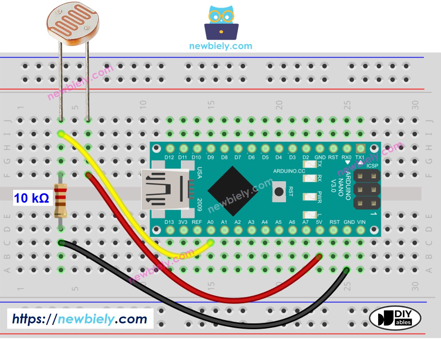
This image is created using Fritzing. Click to enlarge image
Arduino Nano Code
The code below reads the value from a photocell and determines the light level qualitatively.
Detailed Instructions
- Copy the code and open it with the Arduino IDE.
- Click the Upload button on the IDE to transfer the code to the Arduino Nano.
- Open the Serial Monitor.
- Shine light onto the sensor.
- Check out the result on the Serial Monitor.
Light Sensor and LED
- When it is dark, the code below will turn the LED ON. Otherwise, the LED will be switched OFF.
- The wiring diagram for the above code:
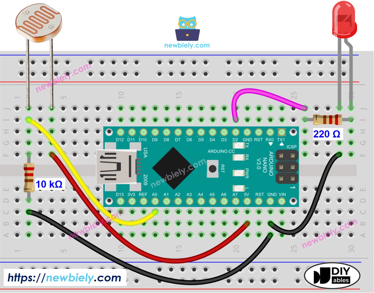
This image is created using Fritzing. Click to enlarge image
See The best way to supply power to the Arduino Nano and other components.
Video Tutorial
Challenge Yourself
- When the light in your room is dim, activate it automatically.
- Refer to Arduino Nano - Relay for more information.