Arduino Nano - RFID Door Lock
This tutorial instructs you how to build a door lock system using Arduino Nano, RFID/NFC RC522 module, a relay, solenoid lock or electromagnetic lock, and optionally LCD. To make it easy for you, the tutorial instructs you to build the RFID door lock from simple to complex steps. In detail, we will do:
- Part 1: A simple RFID door lock system with Arduino Nano, keypad, solenoid lock or electromagnetic lock, supports a single RFID key
- Part 2: (Optionally) Adding multiple RFID keys supports
- Part 3: (Optionally) Adding LCD display to the RFID door lock.
- Part 4: (Optionally) Adding a door sensor to the RFID door lock.
- Part 5: (Optionally) Managing and storing the valid RFID keys to Arduino Nano's internal EEPROM
- Part 6: (Optionally) Storing the access history to SD Card
If you want to build door lock system using password, please refer to Arduino Nano - Keypad Door Lock
Hardware Preparation
Or you can buy the following kits:
| 1 | × | DIYables Sensor Kit (18 sensors/displays) |
Additionally, some of these links are for products from our own brand, DIYables .
Overview of RFID/NFC RC522 Module, Solenoid Lock and Electromagnetic Lock
If you are unfamiliar with the RFID/NFC RC522 Module, solenoid lock, electromagnetic lock (including pinout, how it works, and how to program), the following tutorials can provide more information:
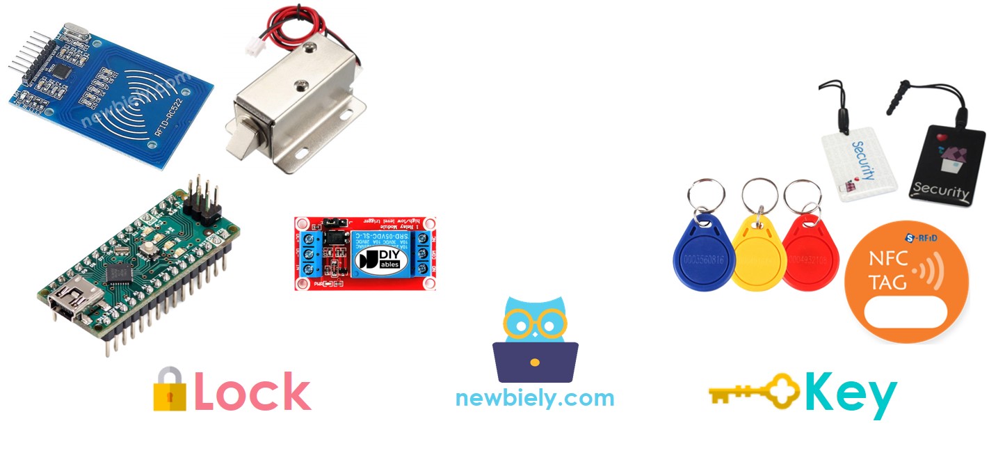
Door Lock System Components
A simple door lock system consists of two components:
- Door Lock: an Arduino Nano, an RFID/NFC reader, a relay, and a solenoid lock or an electromagnetic lock
- Door Key: RFID/NFC tags
How RFID/NFC Door Lock Works
- The user taps an RFID/NFC tag on the RFID/NFC reader, which reads the UID from the tag.
- Arduino Nano then obtains this UID from the reader and compares it to the UIDs that have been set in the Arduino Nano code.
- These UIDs act as the authorized keys.
- If the UID matches one of the predefined UIDs, Arduino Nano will deactivate the solenoid lock to unlock the door.
- Arduino Nano will lock the door after a timeout by activating the relay.
Wiring Diagram
- RFID RC522 Door Lock with Solenoid Lock
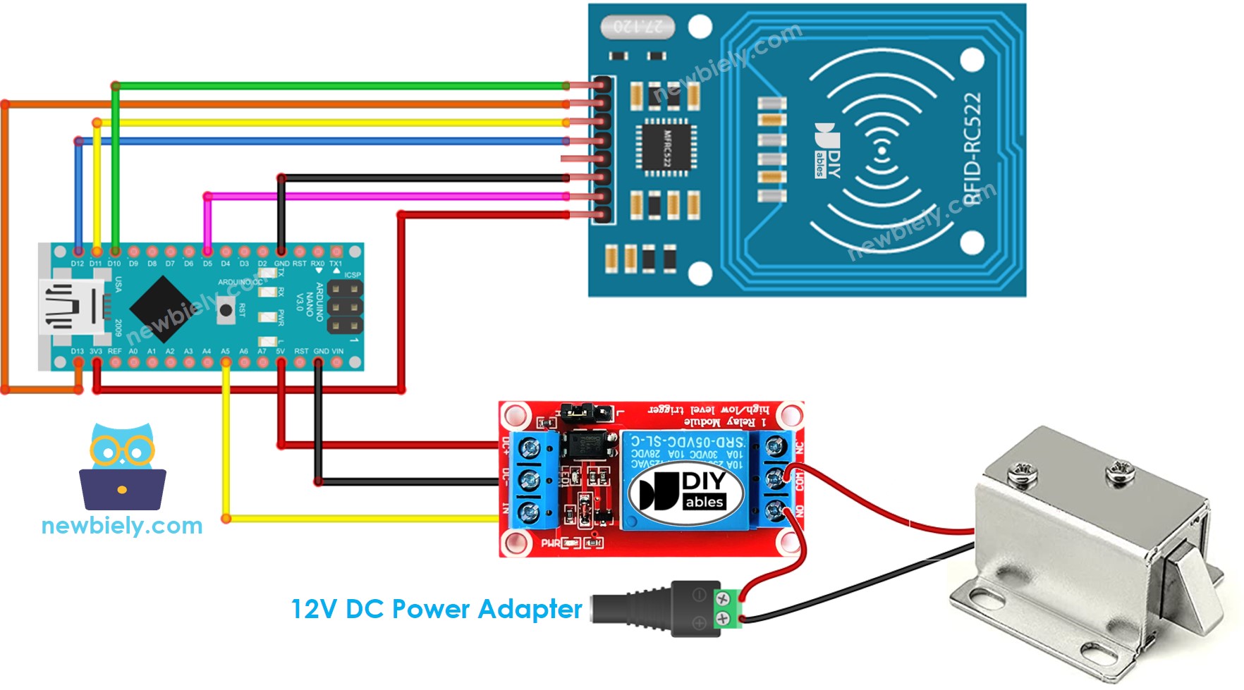
This image is created using Fritzing. Click to enlarge image
- RFID RC522 Door Lock with Electromagnetic Lock
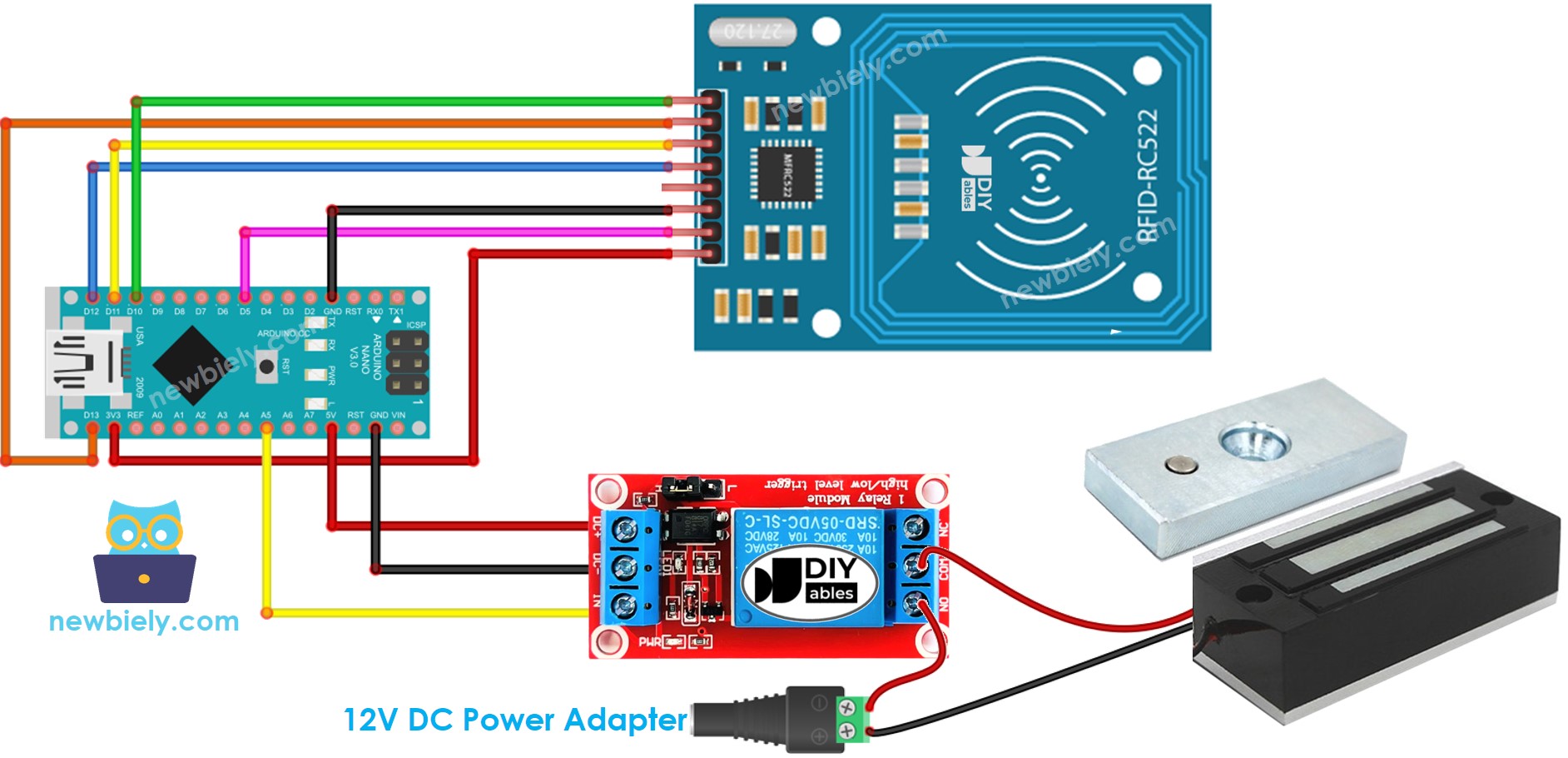
This image is created using Fritzing. Click to enlarge image
To simplify the connection process, the pins of the RC522 module are directly connected to the Arduino pins. However, this can cause the Arduino to malfunction in some cases since the output pins of the Arduino produce 5V, while the RC522 module's pins operate at 3.3V. As a result, it is recommended to regulate the voltage between the pins of the Arduino and the RC522 module. The diagram below demonstrates how resistors can be utilized to regulate 5V to 3.3V.

This image is created using Fritzing. Click to enlarge image
※ NOTE THAT:
Manufacturers may arrange the order of pins differently, so it is important to rely on the labels printed on the module. The pinout diagram depicted above displays the pin arrangement for modules produced by the manufacturer DIYables.
Arduino Nano Code - Single Key
Detailed Instructions
In order to discover the UID of an RFID/NFC tag:
- Upload the above code to Arduino Nano using the Arduino IDE
- Open the Serial Monitor and tap the tag on the RFID-RC522 module. The UID will be displayed on the Serial Monitor.
Once you have the UID:
- Amend line 18 of the code to reflect the UID, e.g. change byte keytagUID[4] = {0xFF, 0xFF, 0xFF, 0xFF}; to byte keytagUID[4] = {0x3A, 0xC9, 0x6A, 0xCB};
- Upload the revised code to the Arduino Nano
- Place an RFID/NFC tag on the RFID-RC522 module
- Check the output on the Serial Monitor
- Verify that the solenoid lock is not deactivated.
- Tap a different RFID/NFC tag to the RFID-RC522 module.
- Check out the output on the Serial Monitor.
※ NOTE THAT:
- To facilitate testing, the unlocked time has been set to 2 seconds; however, it should be increased for practical use/demonstration.
- Installation of the MFRC522 library is required. For more information, please refer to the Arduino Nano - RFID/NFC RC522 tutorial.
Arduino Nano Code - Multiple Keys
Let us envision a room where only the manager and secretary can open the door.
In this instance, two RFID/NFC tags are required: one for the manager and the other for the secretary. The UIDs of both tags must be specified in the code.
Repeat the same steps as before, and then individually select each tag on the RFID-RC522 module. The output on the Serial Monitor should appear like this:
You can expand the code mentioned above to include three, four, or more tags.
Adding LCD Display to the RFID Door Lock
We can optionally add a LCD display to show the access status (e.g. GRANTED/DENIED) to users. You can learn more about LCD in Arduino Nano - LCD tutorial
Wiring diagram - Door lock system using RFID, solenoid lock or electromagnetic lock, and LCD display
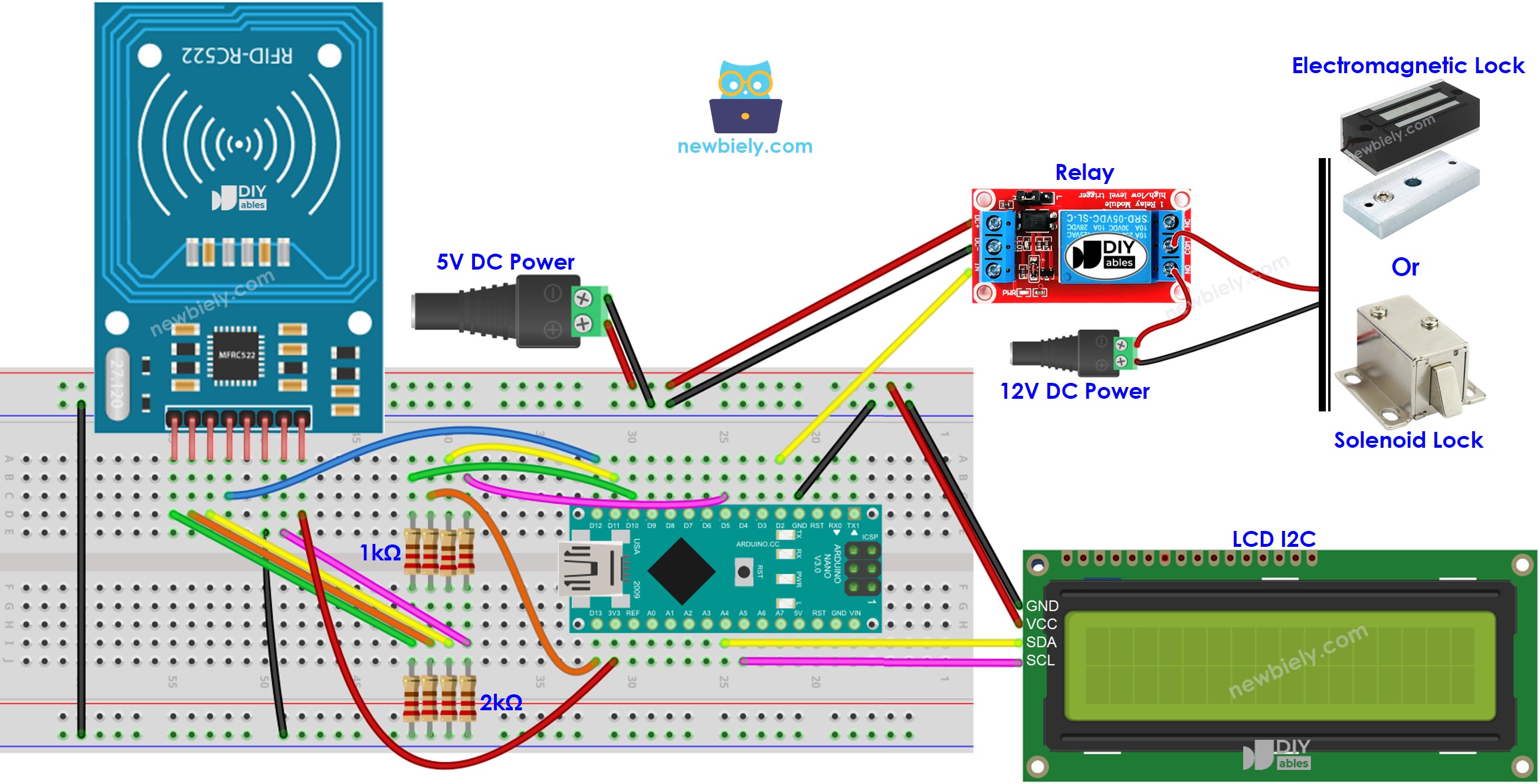
This image is created using Fritzing. Click to enlarge image
See The best way to supply power to the Arduino Nano and other components.
Please note that in the wiring diagram above, 5V power is added because the 5V pin of the Arduino cannot supply enough power for both the relay and LCD simultaneously.
Arduino Nano Code - Door lock system with password using RFID RC522 module, solenoid lock or electromagnetic lock, and LCD display
※ NOTE THAT:
The address of the LCD can differ depending on the manufacturer. We used 0x27 in our code, as specified by DIYables.
Adding a door sensor to the RFID door lock
In the previous code, the door would lock after a certain amount of time since it was unlocked by the Arduino Nano. However, in real-world scenarios, a door sensor is often integrated into the system. If the door is closed, the Arduino Nano would lock the door immediately without waiting for the timeout period to expire.
To not overload you, we do not add the door sensor to the wiring diagram and code. We let this part for your creativeness. You can refer to Arduino Nano - Door Sensor and Arduino Nano - Door Sensor control Relay tutorials.
Managing and storing the valid RFID keys to EEPROM
In the previous example, the valid RFID keys (UID) were hard-coded in the Arduino Nano code. This means that if you wanted to add or delete RFID keys, you would need to modify the code and upload it to the Arduino Nano again, which can be inconvenient.
To make things more practical, we need a way to manage RFID keys without having to modify and upload the code to the Arduino Nano every time. One solution is to store the RFID keys in EEPROM instead of hard-coding them. Consequently, we need a method that allows for adding or deleting RFID keys from the EEPROM without needing to change the code.
There are two methods for managing RFID keys in EEPROM:
- RFID keys as master keys
- Use a RFID key as a ADD master key for adding new key. After the Arduino detects the ADD master key, it switches between the ADD mode and OPERATION mode.
- In the ADD mode, if the Arduino detects a new key, it adds the key to EEPROM
- Similar to DELETE master key and DELETE mode.
- Write a ADD/DELETE commands via Serial/Bluetooth/IR
- Commands are sent via Serial/Bluetooth/IR using Serial Monitor, Bluetooth app, IR controller...
- Commands included: directive (ADD/DELETE), UID of RFID key.
- To enhance the security, the command should also include a password. Arduino vefiry the password to determine if the command is valid or not.
Both methods require to add a lot of Arduino code. That is not an easy task for newbies. Therefore, this tutorial only provides the knowledge to help newbies know more about the door lock system without overloading newbie by the complicated code. If you want to implement this for practical use, please contact us via our paid programming service
Storing the access history to SD Card
You may want to store the access history with the following information: UID of RFID key, access status (GRANTED/DENIED), and date time. You can use SD card to keep the history because EEPROM is not big enough to store the history. You can refer to this Arduino Nano - Log Data with Timestamp to SD Card tutorial.