Arduino Nano - Motion Sensor
Have you ever wondered: “How can it do that?” when you come across places with automatic doors, lights and escalators? If so, this tutorial will not only answer your question, but also show you how to make it happen by using Arduino Nano and motion sensor. Let's get started!
This tutorial instructs you how to use Arduino Nano with motion sensor. In detail, we will learn:
- How HC-SR501 motion sensor works
- How to connect the HC-SR501 motion sensor to Arduino Nano
- How to program Arduino Nano to read the state from the HC-SR501 motion sensor
- How to use Arduino Nano and HC-SR501 motion to detect human presence and take action accordingly.
Hardware Preparation
Or you can buy the following kits:
| 1 | × | DIYables Sensor Kit (18 sensors/displays) |
Additionally, some of these links are for products from our own brand, DIYables .
Overview of HC-SR501 Motion Sensor
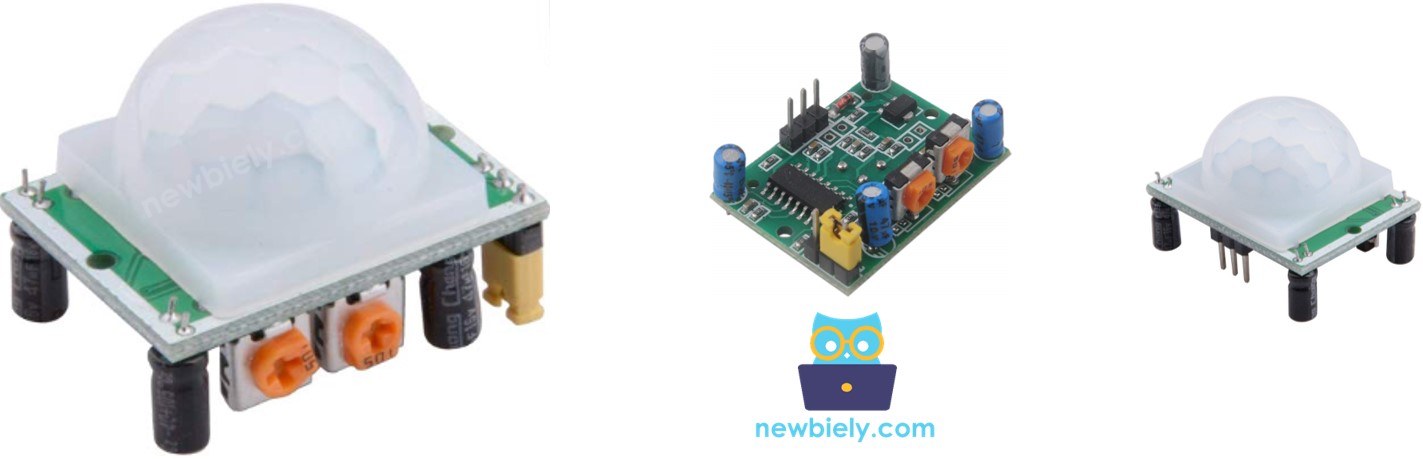
The HC-SR501 PIR sensor is capable of detecting the motion of humans (or animals). It is commonly used in various applications, such as automatically turning a light bulb on or off, opening and closing a door, activating or deactivating an escalator, and detecting an intruder.
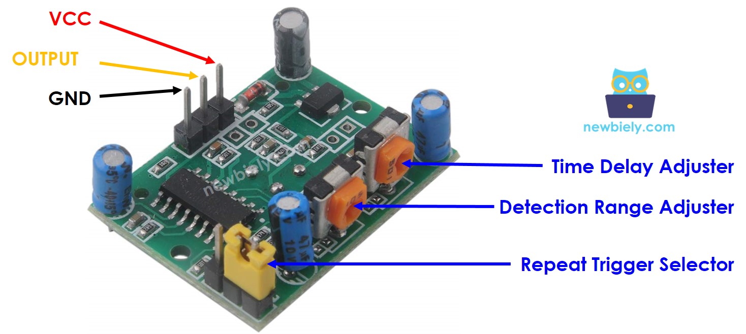
The Motion Sensor Pinout
The HC-SR501 motion sensor has 3 pins:
- GND pin: This should be connected to GND (0V)
- VCC pin: This should be connected to VCC (5V)
- OUTPUT pin: This is an output pin and it will be LOW when no motion is detected, and HIGH when motion is detected. This pin needs to be connected to Arduino's input pin.
The HC-SR501 has a jumper and two potentiometers that are used to adjust the sensor's settings.
How It Works
The HC-SR501 sensor is capable of detecting motion based on the changes of infrared radiation from a moving object. In order for the HC-SR501 sensor to detect the object, two criteria must be met:
- The object must be in motion or shaking
- The object must be emitting infrared radiation
Consequently:
- If an object is moving but not emitting infrared rays (e.g., a robot or vehicle toy), it will not be detected by the sensor.
- If an object is emitting infrared rays but not moving (e.g., a person standing still), it will not be detected by the sensor.
Humans and animals are sources of infrared radiation. Consequently, the sensor can detect their movements.
State of OUTPUT pin:
- When no human (or animal) is present in the detected range of the sensor, the OUTPUT pin of the sensor is LOW.
- If a human (or animal) enters the detected range of the sensor, the OUTPUT pin will transition from LOW to HIGH, indicating motion has been detected.
- When the human (or animal) leaves the detected range of the sensor, the OUTPUT pin will switch from HIGH to LOW, signifying that the motion has ended.
The video above demonstrates the basic functioning of a motion sensor. In reality, the motion sensor may operate differently depending on the configuration (which is described in the Advanced Uses section).
Detect the Presence of Human
The sensor itself does not recognize the presence of humans. It only detects the motion. We use an Arduino Nano to infer humans presence based on the motion detected by the sensor, following this rule:
- If motion is detected, then humans are present.
- If no motion is detected, then humans are not present.
This rule work imperfectly in a practical situation: when humans are within the range of the sensor but not moving, the motion will not be detected. Consequently, the Arduino Nano will conclude that no humans are present.
For instance, the motion sensor in your meeting room is set up to activate the lights when people is present. When the meeting is in progress and no one is moving, the motion is not detected and thus the human presence is not recognized, resulting in the lights being switched off. To turn them back on, someone needs to move.
However, this issue is NOT serious and the sensor is inexpensive. Therefore, it is widely used to detect humans in many applications.
Arduino Nano - HC-SR501 Motion Sensor
Connect an Arduino's digital input pin to the OUTPUT pin of the HC-SR501 sensor. Using the Arduino Nano code, we can check the value of the OUTPUT pin to detect motion.
Wiring Diagram
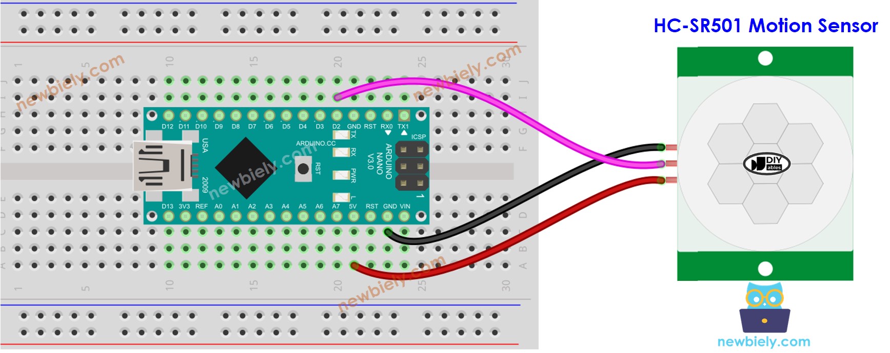
This image is created using Fritzing. Click to enlarge image
See The best way to supply power to the Arduino Nano and other components.
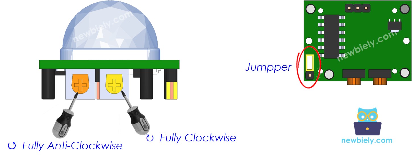
Initial Setting
| Time Delay Adjuster | Screw it in anti-clockwise direction fully. |
| Detection Range Adjuster | Screw it in clockwise direction fully. |
| Repeat Trigger Selector | Put jumper as shown on the image. |
How To Program For Motion Sensor
- Set up an Arduino's pin as a digital input by utilizing the pinMode() function.
- Check the state of the OUTPUT pin of the sensor with the digitalRead() function.
- Identify when motion begins (the pin's state changes from LOW to HIGH).
- Identify when the pin's state has changed from HIGH to LOW indicating motion has stopped.
Arduino Nano Code
Detailed Instructions
- Copy the code above and open it in the Arduino IDE.
- Click the Upload button in the Arduino IDE to compile and upload the code to the Arduino Nano.
- Open the Serial Monitor.
- Move your hand within the range of the sensor.
- Check the output in the Serial Monitor.
Video Tutorial
Advanced Uses
As stated previously, we can alter the sensor's configuration using one jumper and two potentiometers.
Detection Range Adjuster
This potentiometer can change how far something can be detected (about 3 to 7 meters).
- Turning it all the way to the right makes it detect things up to 3 meters away.
- Turning it all the way to the left makes it detect things up to 7 meters away.
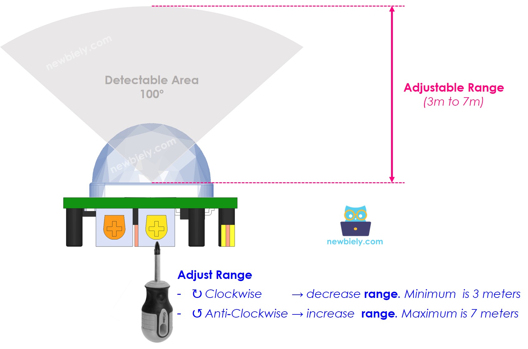
We can use the potentiometer to set a range of values between 3m and 7m.
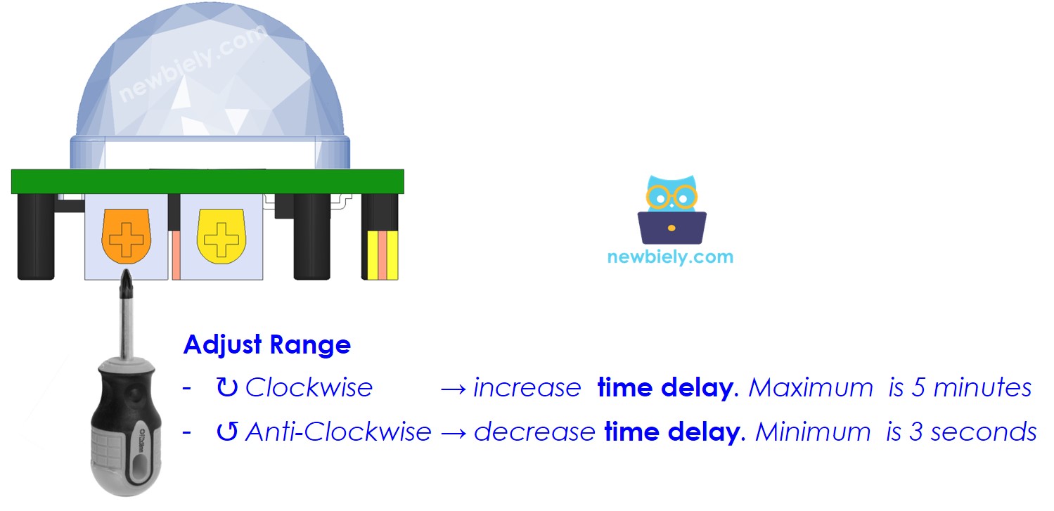
Time Delay Adjuster
This potentiometer is utilized to modify the time delay:
- When it is turned all the way in a clockwise rotation, the time delay is roughly 5 minutes.
- When it is turned all the way in an anti-clockwise direction, the time delay is approximately 3 seconds.
The following section provides an explanation of the concept of time delay in conjunction with Repeat Trigger.
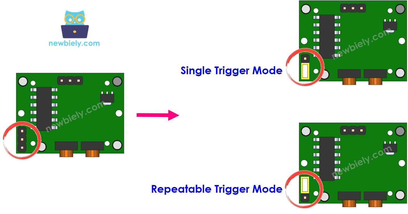
Repeat Trigger Selector
A jumper exists that is utilized to choose between trigger modes: single trigger or repeatable trigger.
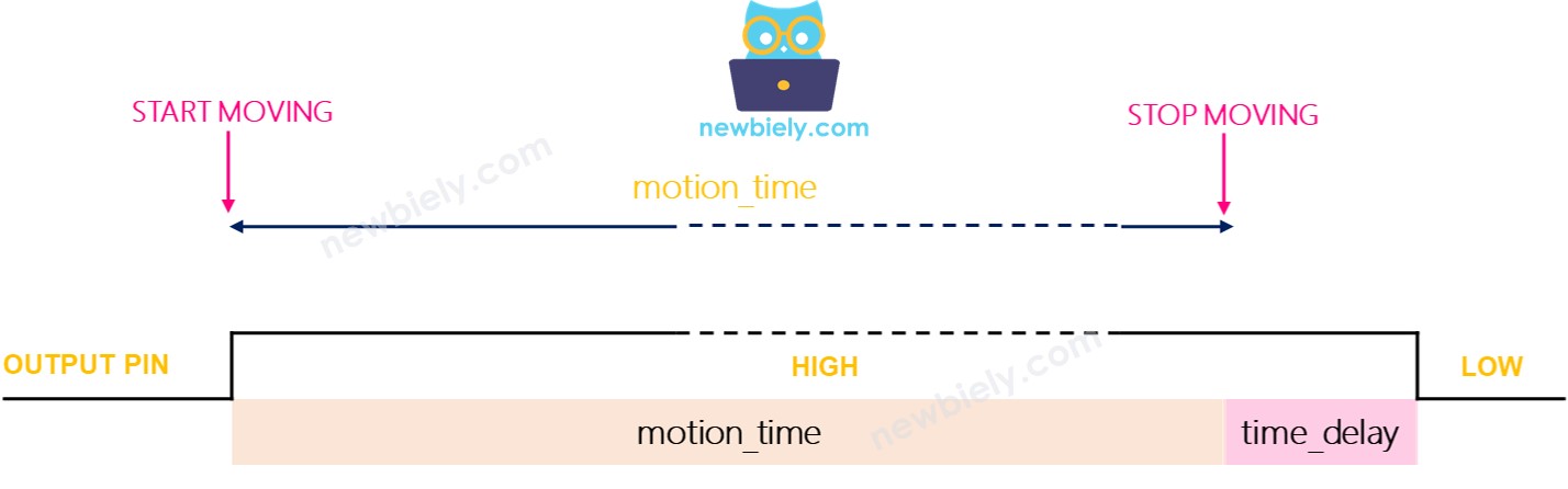
Let's refer to the time delay setting, which is set via the Time Delay Adjuster, as time_delay. If you move within the range of the sensor for a long period of time (known as motion_time) that is several times longer than time_delay:
- In Single Trigger Mode: the OUTPUT pin's state will be toggled between LOW and HIGH multiple times. The HIGH duration will be equal to time_delay while the LOW duration is fixed at 3 seconds.
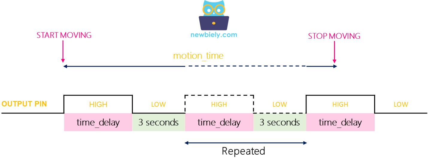
- Repeatable trigger mode: The state of the OUTPUT pin will remain HIGH for a period of (motion_time + time_delay).
Testing
- Single trigger mode:
- Place the jumper to select the single trigger mode
- Wave your hand in front of the sensor for around 10 seconds.
- Move your hand away from the sensor's area
- Wait for 3 seconds, you should observe the output in serial monitor as follows:
- Place the jumper to choose Repeatable trigger mode
- Wave your hand in front of the sensor for around 10 seconds
- Move your hand away from the sensor's reach
- Wait for 3 seconds, the output will be visible in the serial monitor like this:
- We turn on or activate devices/machines as soon as a human is present
- We do NOT turn off or deactivate devices/machines immediately after a human is no longer present. We turn off or deactivate devices/machines after a certain amount of time has passed.
Repeatable trigger mode:
We can observe that when in single trigger mode, the sensor will activate two or three times. Whereas, when in repeatable trigger mode, the sensor will only trigger once.
※ NOTE THAT:
During the LOW time (3 seconds, a fixed and unadjustable value), the sensor is unable to detect any motion. This does not cause any issues in practice.
It is suggested to use the repeatable trigger mode.
In many real-world scenarios:
How To Use Time Delay
If no human is detected, the automation system will wait for a period of time before taking action.
The motion sensor has a Time Delay Adjuster which can be used to set the time delay to a minimum of 3 seconds and a maximum of 5 minutes. Additionally, the Arduino Nano code can be used to set any value for the time delay.
If we do not specify a timeout in the Arduino Nano code, the timeout will be equivalent to the time delay set in the sensor.
If a timeout is established in the Arduino Nano code, it will be the aggregate of the time delay in the sensor's configuration and the time delay in the Arduino Nano code.
Setting time delay in Arduino Nano code
If the repeatable trigger mode is enabled, then the delay in the code will be 30 seconds plus time_delay, which is set on the sensor's settings through the Time Delay Adjuster.
Challenge Yourself
Utilize the motion sensor to carry out one of these projects:
- Activate the light when you enter your room and switch it off after 30 seconds of your departure. Tip: Check out Arduino Nano - Relay.
- Instigate an alarm when someone approaches your prized possessions. Tip: Check out Arduino Nano - Piezo Buzzer.