Arduino Nano - LCD
This tutorial instructs you how to use LCD display with Arduino Nano, how to program for Arduino Nano to display text, special characters on LCD.
Hardware Preparation
Or you can buy the following kits:
| 1 | × | DIYables Sensor Kit (30 sensors/displays) | |
| 1 | × | DIYables Sensor Kit (18 sensors/displays) |
Additionally, some of these links are for products from our own brand, DIYables .
Overview of LCD I2C 16x2
LCD I2C is made up of a standard LCD, an I2C module and a potentiometer. It is highly recommended to use the LCD I2C instead of standard LCD. That is because using the LCD I2C make the wiring much easier.
The LCD Pinout
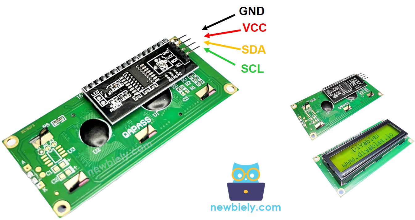
The LCD I2C uses the I2C interface to connect to Arduino Nano. It has four pins:
- The GND pin needs to be connected to ground (0V).
- The VCC pin is the power supply for the LCD and must be connected to VCC (5V).
- The SDA pin is the I2C data signal.
- The SCL pin is the I2C clock signal.
LCD Coordinate
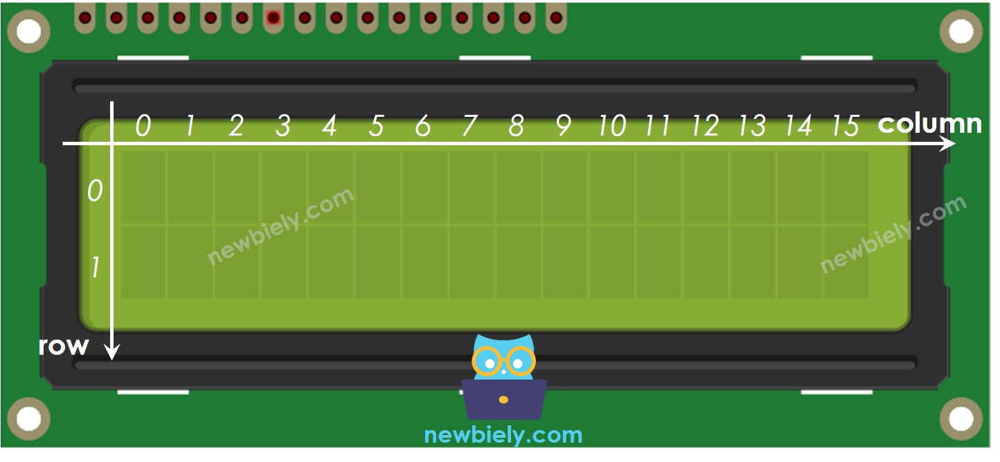
The LCD I2C 16x2 has 16 columns and 2 rows, with the columns and rows being numbered starting from 0.
Wiring Diagram

This image is created using Fritzing. Click to enlarge image
See The best way to supply power to the Arduino Nano and other components.
| LCD I2C module | Arduino Nano |
|---|---|
| Vin | 5V |
| GND | GND |
| SDA | A4 |
| SCL | A5 |
How To Program For LCD I2C
The LiquidCrystal_I2C library needs to be included in order to use the LCD.
- Set up the LCD:
The LCD must be set up properly for it to work correctly.
- Write to the LCD:
Writing to the LCD is easy thanks to the LiquidCrystal_I2C library.
- Create a LiquidCrystal_I2C object with an I2C address, the number of columns, and the number of rows specified.
- Start up the LCD.
- Go to the column and row indicated by column_index and row_index respectively.
- Display a message on the LCD.
Explore the possibilities of what can be achieved with LCD by looking at the "Do More with LCD" section.
※ NOTE THAT:
The address of the LCD may differ depending on the manufacturer. For our code, we used 0x27 as specified by DIYables.
Arduino Nano Code
Detailed Instructions
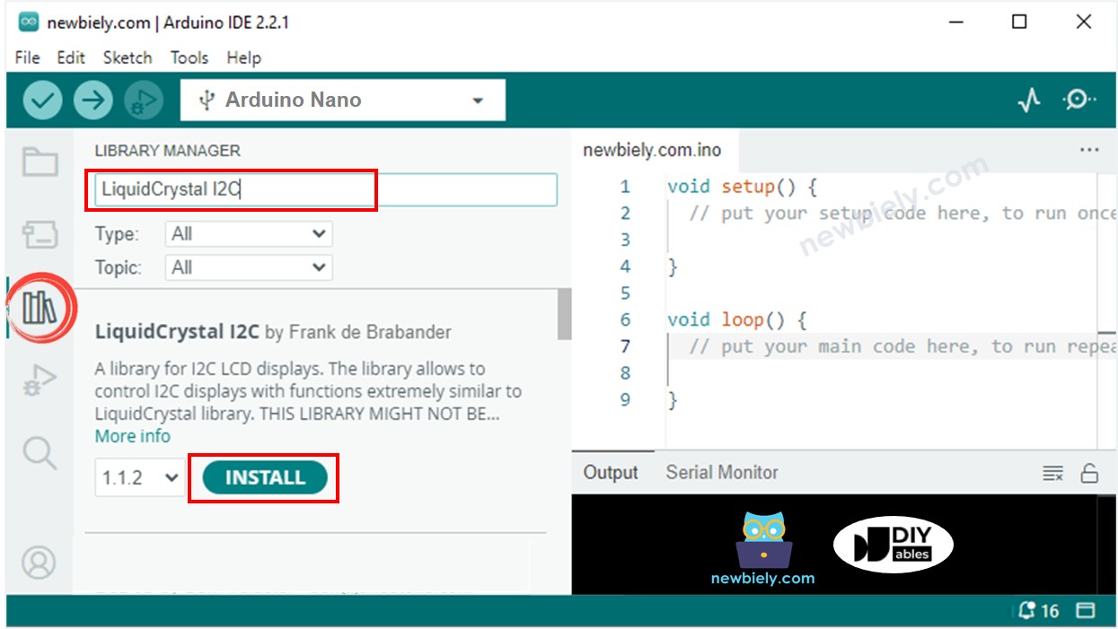
- Click to the Libraries icon on the left bar of the Arduino IDE.
- Search for "LiquidCrystal I2C" and locate the LiquidCrystal_I2C library created by Frank de Brabander.
- Then, click the Install button to add the library.
- Copy the code and open it with the Arduino IDE.
- Click the Upload button in the IDE to send the code to the Arduino Nano.
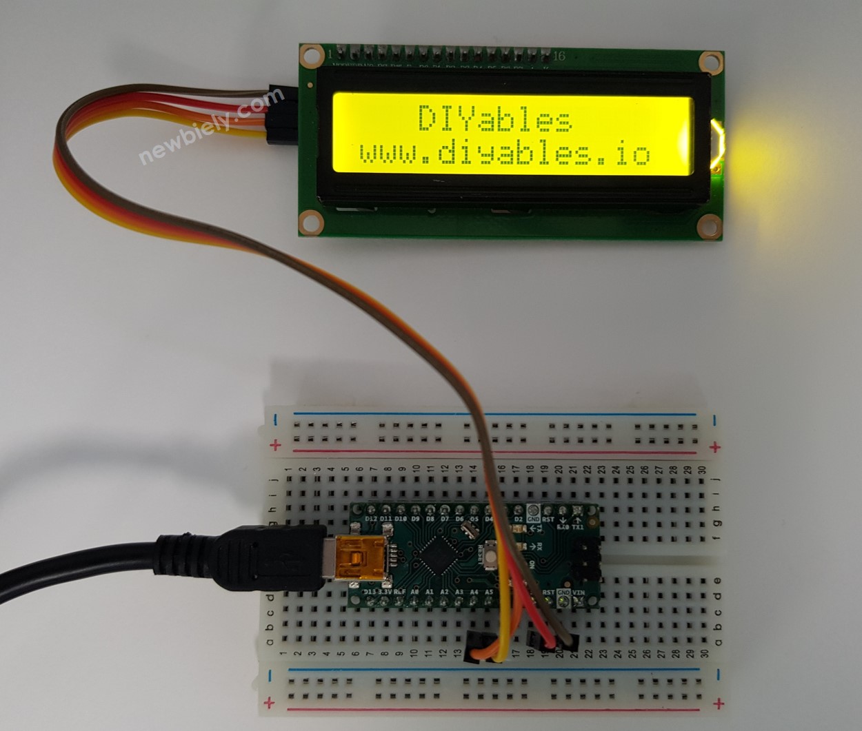
- Check the LCD for the result.
- Experiment with altering the text and its location.
Guide for Choosing an LCD I2C Display
There are many types of LCD I2C displays available, mainly differing in background color and the shape of the I2C interface module.
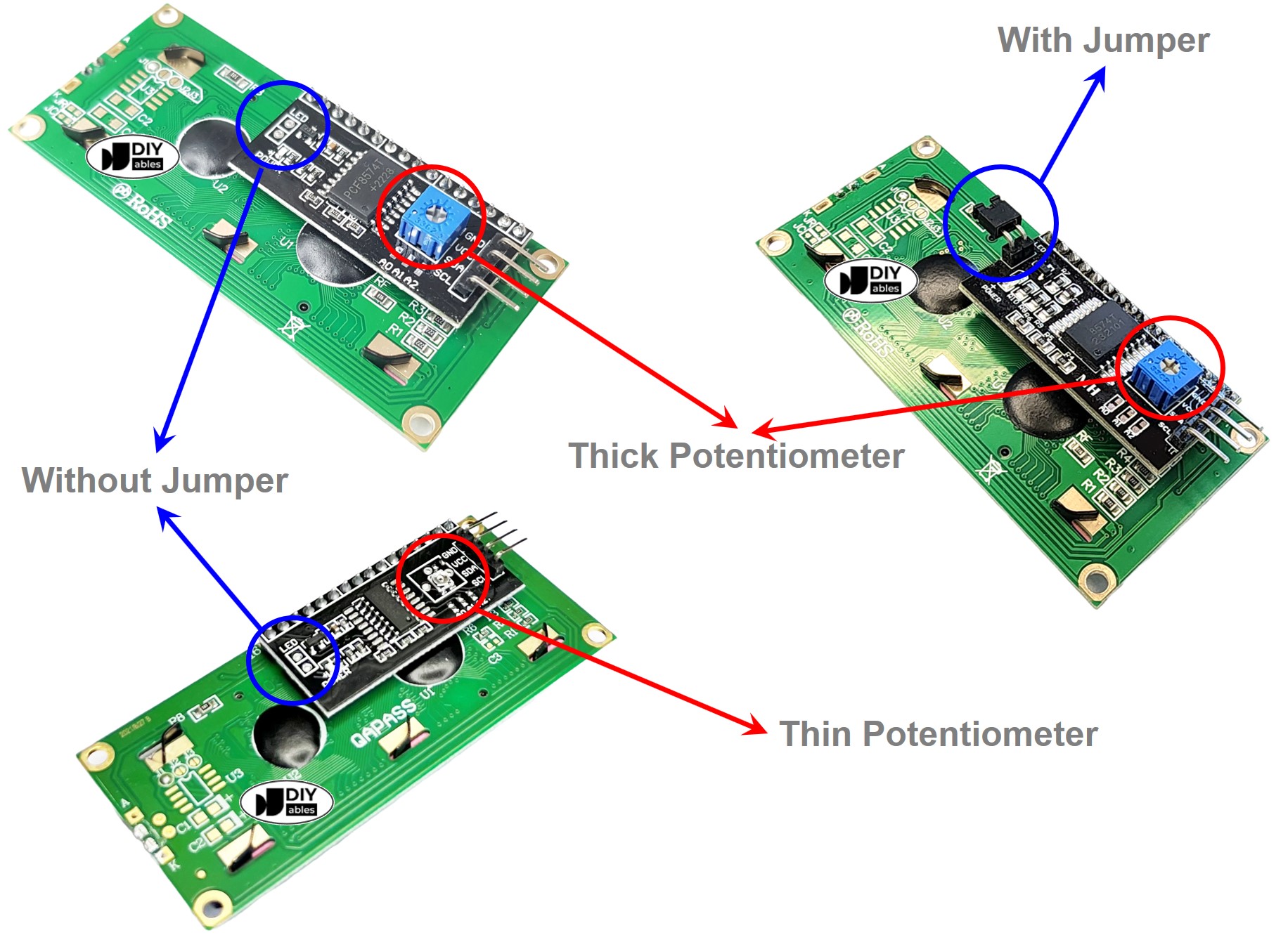
Regarding color, these displays usually come in two background colors: green and blue.
For the shape of the I2C interface module, consider two main aspects:
- Potentiometer size: This includes options for thin and thick potentiometers.
- Thick potentiometer: Easier to adjust but takes up more space.
- Thin potentiometer: More compact and saves space due to its smaller height.
- I2C selection jumper:
- With jumper: Allows switching between two I2C addresses, useful when your code uses two LCD displays simultaneously. However, it can cause confusion with I2C addresses when only one LCD is used and it also requires more space.
- Without jumper: Has a fixed I2C address and is very convenient when your code uses just one LCD display. Since most applications use only one LCD, this type is highly recommended.
Video Tutorial
Do More with LCD
Custom Character
lcd.print() only works with ASCII characters. To display a special character or symbol (e.g. heart, angry bird), you must use the character generator.
An LCD 16x2 can show up to 32 characters. Each character is made up of 40 pixels, which are arranged in 8 rows and 5 columns.
The character generator creates a character that is 40 pixels in size. To use it, simply follow these steps:
The LCD showed the result. The result was displayed on the LCD.
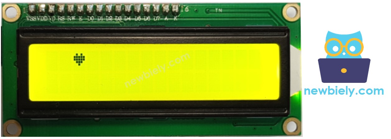
Multiple custom characters
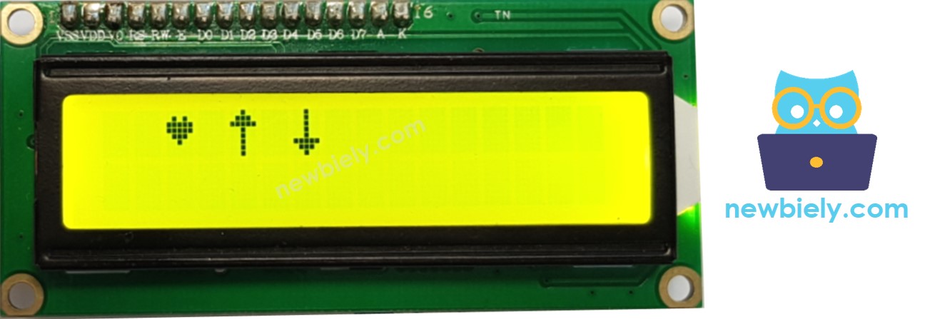
We are able to make a maximum of 8 custom characters, numbered from 0 to 7. The example below shows how to create and display three of them.
The outcome displayed on the LCD is: . The result that appears on the LCD is:
Summary: how to use custom character on LCD
- Employ the character generator to generate binary code for your custom character.
- Copy the binary code generated in the previous step.
- Assign a custom character to an index value ranging from 0 to 7 inside the setup() function.
- Print the custom character on the LCD at any time, either in the setup() or loop() function.
Other functions
- Print "Hello World"
Insert the following functions into the loop() function, one at a time, with a delay of 5000 milliseconds after each:
- Clear the LCD screen
- Print "Hello World"
- Screen
- Position the cursor at the top left corner of the LCD display.
- Position the cursor at a certain column and row.
- Show the LCD cursor on the screen.
- Makes the LCD cursor invisible.
- Show the LCD cursor blinking.
- Disable the blinking of the LCD cursor.
- Additionally, you can find information at LiquidCrystal Library Reference
Challenge Yourself
Try using an LCD for one of these projects:
- Sending text from a computer (via Serial Monitor) and displaying it on the LCD. Hint: See How to send data from PC to Arduino
- Showing the key pressed on the keypad on the LCD. Hint: Check out Arduino Nano - Keypad
Troubleshooting on LCD I2C
- Rotate the potentiometer on the back of the LCD to adjust its contrast.
- Depending on the manufacturer, the I2C address of the LCD may be different. Generally, the default I2C address of the LCD is either 0x27 or 0x3F. Try both these values. If you are still unsuccessful, run the code below to find the I2C address.
The output displayed on the Serial Monitor is: . The outcome that appears on the Serial Monitor is:
