
ESP32 C3 Super Mini - BTS7960 Motor Driver
Hens walk into the coop at dusk and want to go out again at sunrise. An automatic coop door does this job for you: a 12V gear motor winds a cord to lift the door in the morning and lowers it again in the evening. The ESP32 C3 Super Mini makes a good brain for such a door. It is tiny, cheap and has WiFi. But each of its pins gives only a few milliamps at 3.3V, while a motor that lifts a wooden door needs far more. The BTS7960 motor driver fills that gap. On this page, you build the motor part of the door: the C3 lets the motor speed up, slow down, stop hard, turn back and roll freely.
In this tutorial, you'll learn:
- What is on the BTS7960 board, and what each of its 8 control pins is for
- Why the module's VCC pin goes to the 5V pin of the C3, and why B+ must never touch the board
- How RPWM, LPWM, R_EN and L_EN pick forward, reverse, brake or coast
- How to wire the module to a C3 that sits on a breadboard
- How to change the motor speed with analogWrite() and a gentle ramp
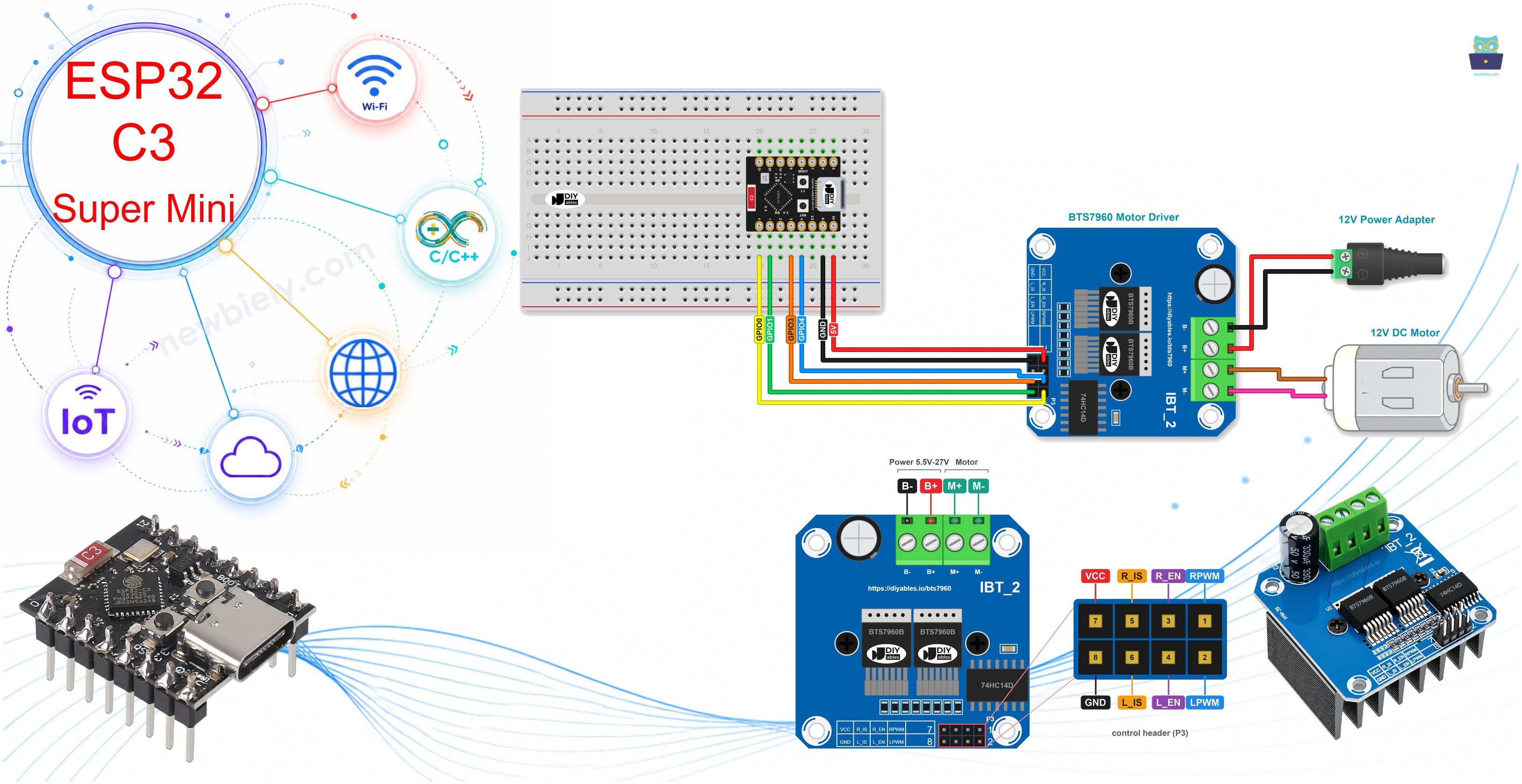
Hardware Preparation
Or you can buy the following kits:
| 1 | × | DIYables Sensor Kit (18 sensors/displays) |
Additionally, some of these links are for products from our own brand, DIYables .
Overview of BTS7960 Motor Driver
The DIYables BTS7960 module controls one brushed DC motor, and it is made for the big ones. Other sellers list this board as IBT-2 or HW-039. Two Infineon BTS7960B chips sit on top of the board, and a big heat sink is bolted under it to keep them cool. Each chip is a half-bridge: it can connect one motor wire to the + or to the - of the motor supply. Together, the two half-bridges make one full H-bridge. When one chip feeds + to its motor wire and the other chip holds the second wire at -, current flows one way and the motor turns forward. Swap the two jobs, and the motor turns in reverse. The control signal switches the power on and off very fast (PWM). The longer the "on" part of each pulse, the faster the motor turns.
Key Features:
- Motor supply (B+ / B-): 5.5V to 27V DC, so 6V, 12V and 24V motors all work
- Current: up to 43A. At that point the chips start to limit the current, so treat it as a short peak. A motor that runs for minutes should pull much less, because the heat sink sets what the board can carry for a long time
- PWM frequency: up to 25 kHz on RPWM and LPWM
- Protection: current limiting and over-temperature protection inside the chips
- Logic side: a 74HC14 buffer chip sits between your board's pins and the power chips
- One motor, both directions: speed control by PWM, plus a brake and a coast mode
Why Pick the BTS7960 for a Coop Door:
- A door can stick in mud, straw or ice. The motor then pulls a big current, and a small driver would give up
- The motor gets its own 12V supply. The C3 only sends four small control signals
- The driver wastes almost no voltage, so nearly all of the 12V reaches the motor
- The brake stops the motor fast when the door reaches the end of its travel
- No library to install: analogWrite() and digitalWrite() are all you need
BTS7960 Pinout
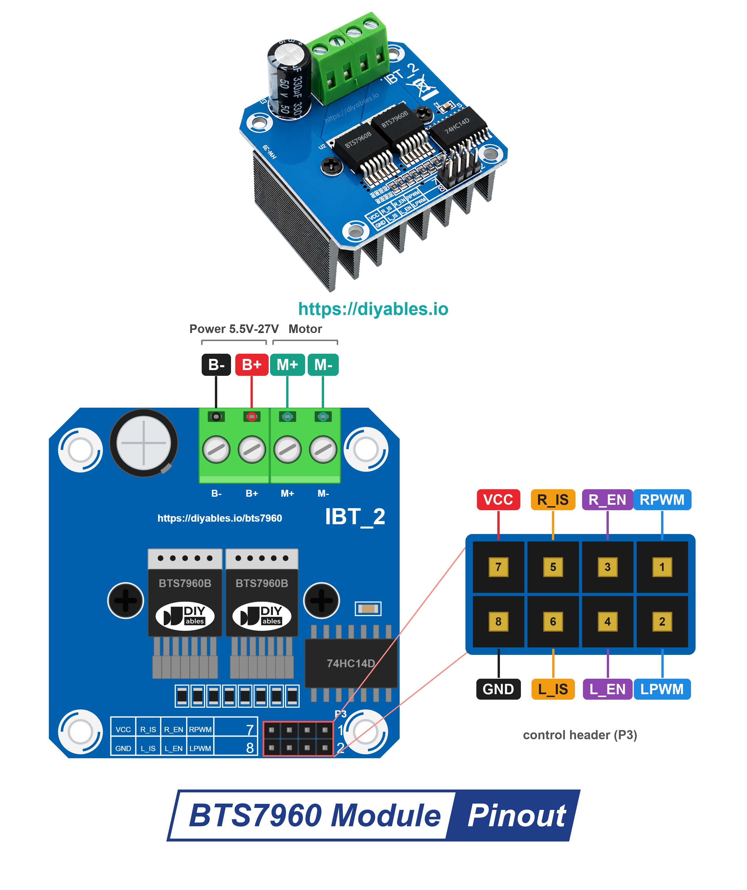
The control header has two rows of four male pins. The silkscreen shortens R_IS and L_IS to "R_S" and "L_S".
- RPWM (pin 1): PWM input of the right half-bridge. It turns the motor forward. Wire it to GPIO0
- LPWM (pin 2): PWM input of the left half-bridge. It turns the motor in reverse. Wire it to GPIO1
- R_EN (pin 3): turns the right half-bridge on (HIGH) or off (LOW). Wire it to GPIO4
- L_EN (pin 4): turns the left half-bridge on (HIGH) or off (LOW). Wire it to GPIO3
- R_IS, L_IS (pins 5 and 6): current sense and fault outputs. This project does not use them, so leave them free
- VCC (pin 7): powers only the logic chip and the power LED, not the motor. Wire it to 5V
- GND (pin 8): ground. On the module, it is joined to B-
The green screw terminal on the other side takes the thick wires:
- B+ and B-: + and - of the motor supply (5.5V to 27V)
- M+ and M-: the two wires of the DC motor
What Each Pin Combination Does
R_EN and L_EN give each half of the bridge permission to work. While both are HIGH, the two PWM pins decide what the motor does:
| RPWM | LPWM | Motor |
|---|---|---|
| PWM (0-255) | 0 | Turns forward. The duty cycle sets the speed |
| 0 | PWM (0-255) | Turns in reverse. The duty cycle sets the speed |
| 0 | 0 | Brake. The driver joins the two motor wires, so the motor stops fast |
Now set R_EN and L_EN LOW. Both halves switch off, and the motor is neither driven nor braked. It coasts and rolls to a stop on its own.
Keep this in mind when you change the code: RPWM and LPWM must never carry PWM together. Before one of them gets a duty above 0, set the other one to 0.
Keeping 3.3V and 12V Apart
- Motor power: the 12V adapter plugs into the DC power jack. The + screw of the jack goes to B+, the - screw goes to B-. Make sure the adapter can supply more current than the door motor draws.
- VCC on 5V: VCC feeds only the small buffer chip, and the maker of the module asks for 5V there. The control pins still take 3.3V signals, so the C3 pins drive them straight away. Pull-down resistors sit on these inputs, so no 5V flows back into a C3 pin.
- Only signals go out: the C3 talks to the module, but the module sends nothing back, because R_IS and L_IS are left free. So the 12V side cannot push a voltage into a C3 pin.
- Shared ground for free: on the module, GND is already joined to B-. So the wire from the G pin of the C3 to GND of the module also ties the C3 to the ground of the 12V supply.
- Keep 12V away: never connect B+ to any pin of the ESP32 C3 Super Mini.
※ NOTE THAT:
BTS7960 or a smaller driver? An L298N drives two motors at about 2A each, but it loses about 2V inside. The BTS7960 drives only one motor, with a much higher current and very little loss. For small motors, like the wheels of a palm-sized robot, see ESP32 C3 Super Mini - DRV8833 DC Motor Driver.
Wiring Diagram between BTS7960 and ESP32 C3 Super Mini
Press the ESP32 C3 Super Mini into the breadboard so that it sits across the middle gap. Each pin of the board now has its own breadboard column, and the free holes of that column carry the same signal. All six wires leave from the lower row of pins, the one printed 5V, G, 3.3, 4, 3, 2, 1, 0. Each wire starts in a free hole next to its pin and ends on a pin of the BTS7960 control header. The module stays off the breadboard, because its header already gives the wires something to plug onto. The 12V adapter and the motor go only to the green screw terminal of the module.
Why these pins? They all sit in one row, so the wires stay short. GPIO2 is in that row too, but it is a boot strapping pin of the ESP32-C3, so we jump over it. GPIO0 and GPIO1 carry the PWM signals. GPIO3 and GPIO4 only switch the enable pins HIGH or LOW. The VCC wire starts next to the 5V pin at the end of the row, so the 3.3 pin stays empty.
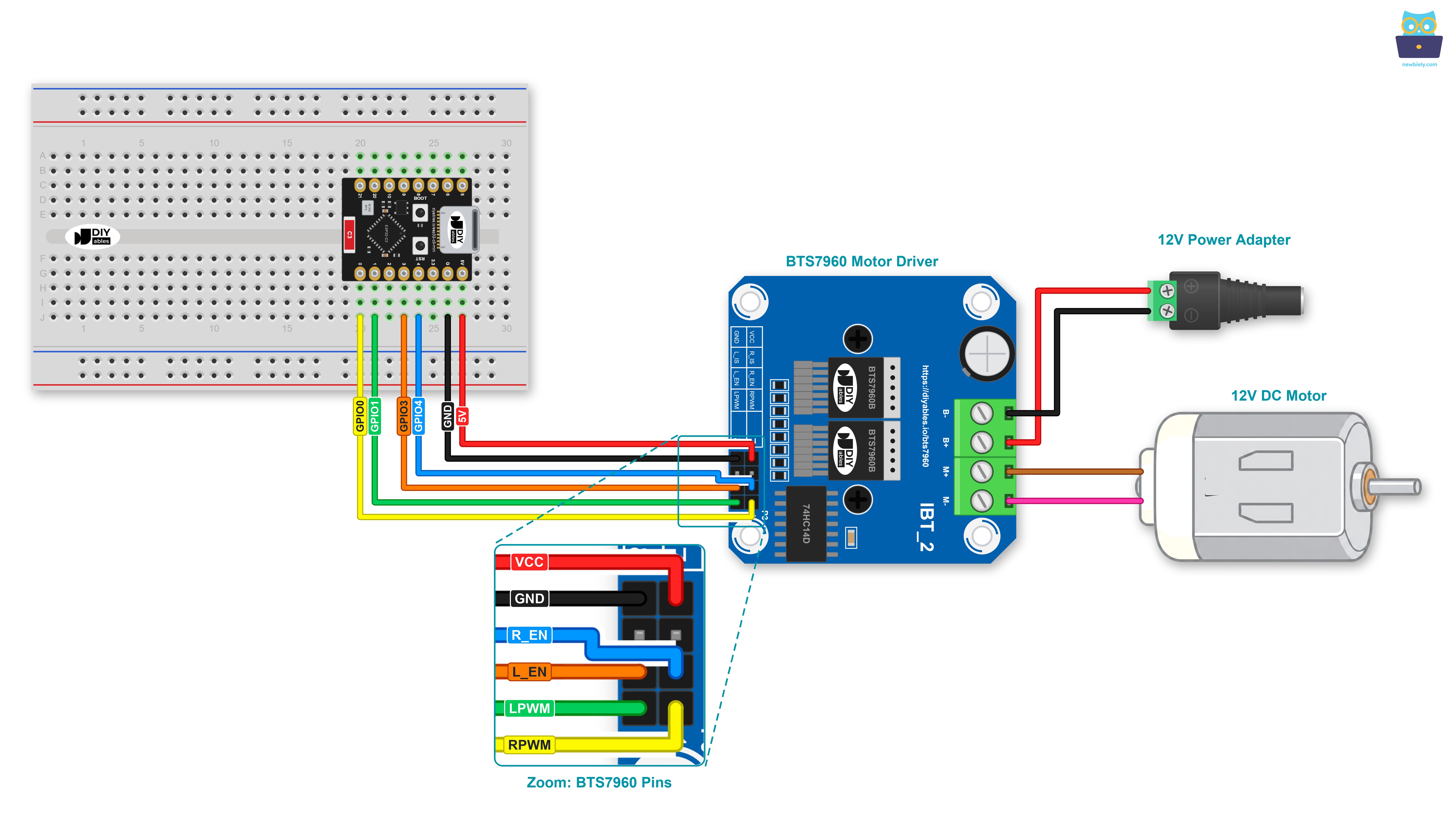
This image is created using Fritzing. Click to enlarge image
| BTS7960 Pin | Goes To |
|---|---|
| RPWM | GPIO0 |
| LPWM | GPIO1 |
| R_EN | GPIO4 |
| L_EN | GPIO3 |
| VCC | 5V (printed "5V" on the board) |
| GND | GND (printed "G" on the board) |
| R_IS, L_IS | nothing, leave them free |
| B+ | + of the 12V power adapter, through the DC power jack |
| B- | - of the 12V power adapter, through the DC power jack |
| M+, M- | the two wires of the 12V DC motor |
※ NOTE THAT:
Before the 12V adapter goes into the wall socket: check that + goes to B+ and - goes to B-. A swapped supply can kill the BTS7960 board. Finish all the other wires first and connect the motor power last. Then check the two enable wires once more: GPIO4 belongs to R_EN, GPIO3 belongs to L_EN.
ESP32 C3 Super Mini Code - BTS7960 Motor Driver
The sketch runs the motor through one full cycle and then starts again. For the coop door, think of forward as "door up" and reverse as "door down". Each move prints its own line, so you can match what you hear with what you read.
What the code does:
- Makes GPIO0, GPIO1, GPIO3 and GPIO4 outputs, sets both PWM pins to 0, then sets R_EN and L_EN HIGH
- Raises the forward duty from 0 to 255 in about 2 seconds
- Holds full speed for 2 seconds, then lowers the duty back to 0
- Brakes for 1 second
- Runs the motor in reverse at about half speed (128) for 2 seconds
- Pulls R_EN and L_EN LOW for 2 seconds so the motor coasts, then turns the driver on again
- Uses four small helper functions: motorForward(), motorReverse(), motorBrake() and motorCoast()
Detailed Instructions
- First time with the ESP32 C3 Super Mini? Go through Getting Started with ESP32 C3 Super Mini once, so the ESP32 board package is installed in the Arduino IDE.
- Wire everything: Put the C3 on the breadboard and add the six control wires. Then connect the motor and the DC power jack to the screw terminal. Keep the 12V adapter unplugged.
- Connect USB: Join the ESP32 C3 Super Mini and your computer with a USB Type-C cable.
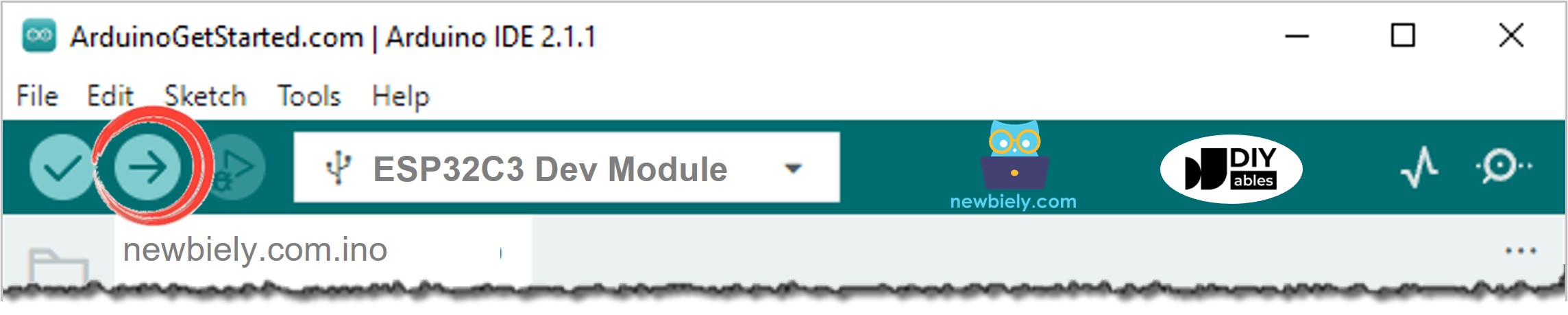
- Choose board and port: In the Arduino IDE, pick ESP32C3 Dev Module under Tools > Board, then the COM port of the board.
- Paste the code: Open a new sketch and paste the code above. There is nothing to install from the Library Manager.
- Upload: Click the Upload button. The 12V adapter is still unplugged at this point.
- Power the motor: Now plug in the 12V adapter.
- Open Serial Monitor: Set it to 115200 baud.
- Watch the motor: It speeds up, runs fast, slows down, stops, turns back slowly, and then drifts to a stop without power. The Serial Monitor names each move:
- Door goes down instead of up? If the "Door up" lines turn the motor the other way than you want, unplug the 12V adapter and change over the two wires on M+ and M-. The sketch stays as it is.
- Pro Tip: At low speed, the motor may hum or whine during the ramps. The sound comes from the PWM signal (about 1 kHz) and is normal. If the Serial Monitor stays empty, set USB CDC On Boot to Enabled in the Tools menu and upload again.
Line-by-line Code Explanation
The above ESP32 C3 Super Mini code contains line-by-line explanation. Please read the comments in the code!
Applications and Project Ideas
The C3 also has WiFi and Bluetooth LE, so the motor does not have to follow a fixed loop. Some ideas:
- Automatic chicken coop door: open and close the door at set times, with the clock taken from the internet over WiFi
- Daylight coop door: let an LDR module tell the C3 when it gets dark outside
- Gate opener: move a light garden gate with a 12V gear motor and buttons on your phone
- Small winch: pull a cart or a small boat up a ramp, slowly and with force
- Wiper motor display: turn a car wiper motor at a slow, steady speed for a rotating sign
- Heavy robot base: use two BTS7960 modules, one for each wheel motor
Video Tutorial
Challenge Yourself
Ready for more? Try these tasks:
- Easy: Change HALF_SPEED from 128 to a smaller number and find the slowest speed at which your motor still turns
- Easy: Raise STEP_DELAY from 8 to 20 for a softer start and a softer stop
- Medium: Add two limit switches, one at the top and one at the bottom of the door, and brake the motor when one of them is pressed
- Medium: Type commands in the Serial Monitor: "u" = door up, "d" = door down, "s" = brake, "c" = coast
- Advanced: Open the door when the LDR module sees daylight and close it after dusk. Wait a few minutes before each move, so a passing cloud does not close the door
- Advanced: Host a small web page on the C3 with "Open" and "Close" buttons for the coop door