Arduino Nano - Measure Voltage

In this guide, we will learn how to measure voltage between 0V and 25V using a voltage sensor with an Arduino Nano. We will discuss:

Arduino Nano voltage sensor

Hardware Preparation

1×Arduino Nano
1×USB A to Mini-B USB cable
1×Voltage Sensor
1×Jumper Wires
1×Breadboard
1×(Recommended) Screw Terminal Expansion Board for Arduino Nano
1×(Recommended) Breakout Expansion Board for Arduino Nano

Or you can buy the following sensor kits:

1×DIYables Sensor Kit (30 sensors/displays)
1×DIYables Sensor Kit (18 sensors/displays)
Disclosure: Some of the links provided in this section are Amazon affiliate links. We may receive a commission for any purchases made through these links at no additional cost to you.
Additionally, some of these links are for products from our own brand, DIYables.

Overview of Voltage Sensor

A Voltage Sensor is a ready-to-use circuit that divides voltage for easy measuring. It has two resistors: one 30 KΩ and one 7.5 KΩ. With a reference voltage of 5V for the ADC, the sensor can measure voltages from 0 to 25V DC. If the reference voltage of the ADC is 3.3V, the sensor can measure from 0 to 16.5V DC.
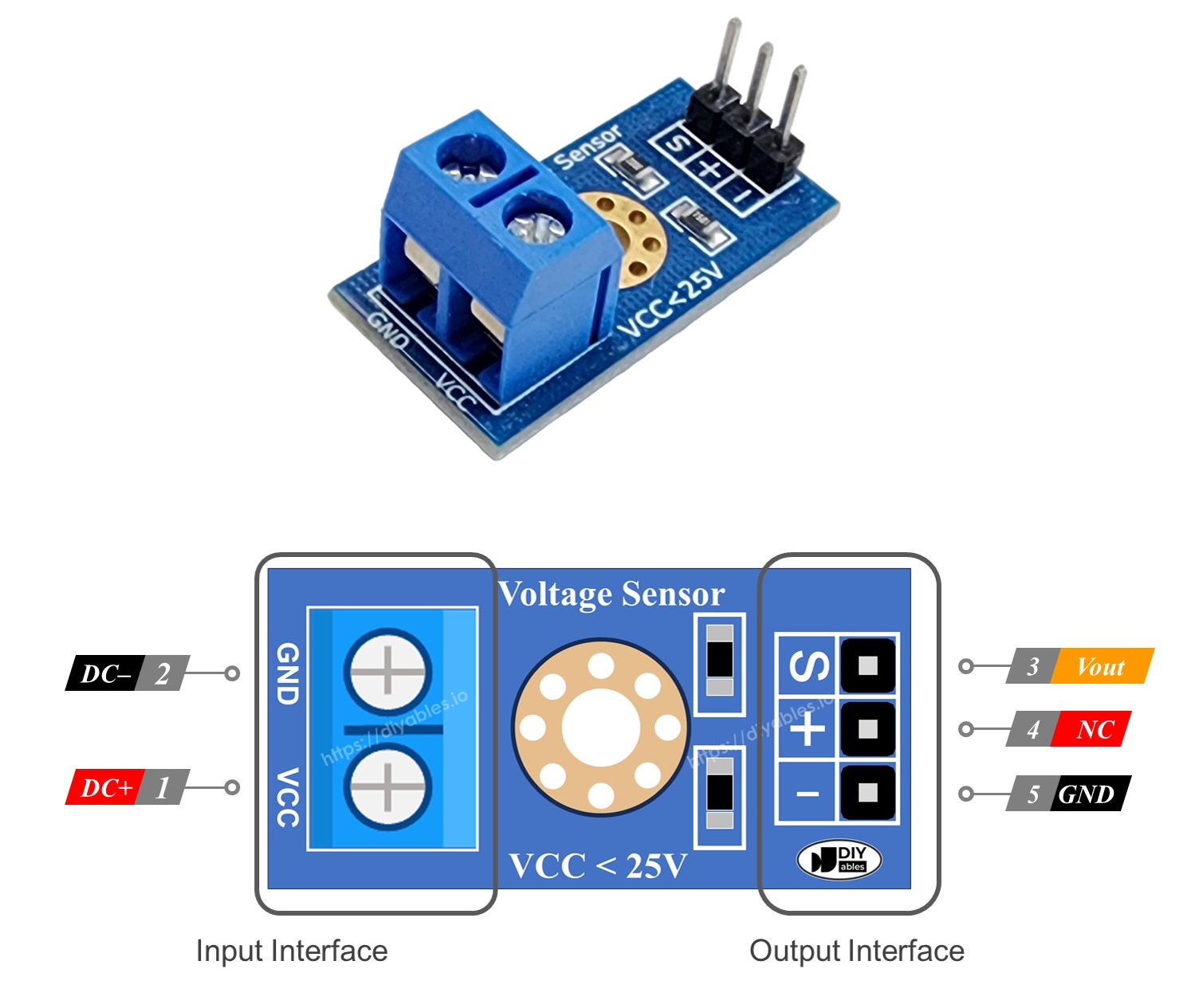
Pinout

A voltage sensor includes two groups of pins.

  • Input Interface (connect where you need to measure voltage):
    • VCC pin: This is the positive pin. Connect it to the point with higher voltage.
    • GND pin: This is the negative pin. Connect it to the point with lower cost.
  • Output Interface (connect to the Arduino Nano):
    • Vout pin (S): This is the signal pin. Connect it to an analog input on the Arduino Nano.
    • NC pin (+): Do not connect this.
    • GND pin (-): This is the ground pin. Connect it to the GND (0V) on the Arduino Nano.
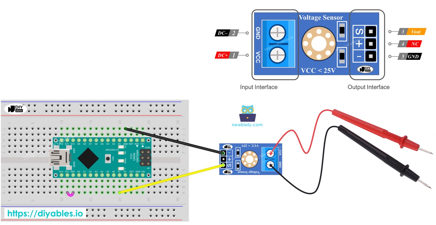
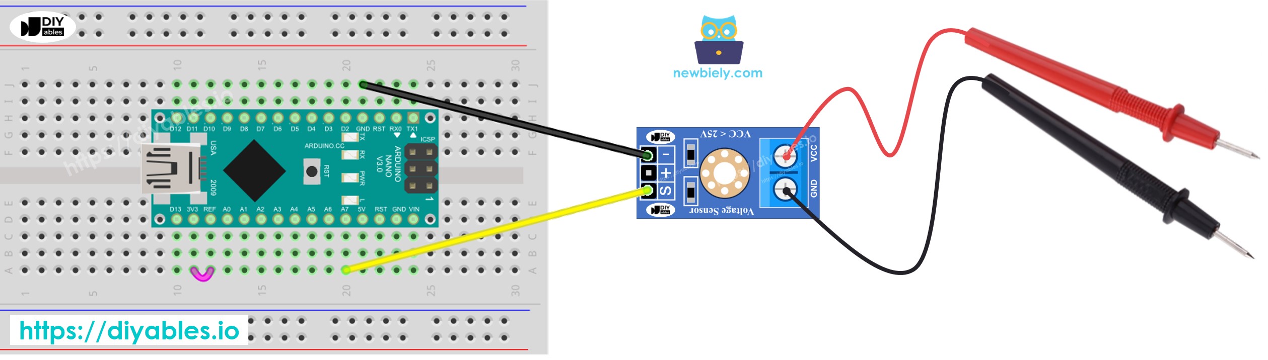
    Voltage Pinout
    image source: diyables.io

Wiring Diagram

The wiring diagram between Arduino Nano and voltage sensor

This image is created using Fritzing. Click to enlarge image

Arduino Nano Code

/* * This Arduino Nano code was developed by newbiely.com * * This Arduino Nano code is made available for public use without any restriction * * For comprehensive instructions and wiring diagrams, please visit: * https://newbiely.com/tutorials/arduino-nano/arduino-nano-measure-voltage */ #define ANALOG_IN_PIN A7 // The Arduino Nano pin connected to voltage sensor #define REF_VOLTAGE 5.0 #define ADC_RESOLUTION 1024.0 #define R1 30000.0 // resistor values in voltage sensor (in ohms) #define R2 7500.0 // resistor values in voltage sensor (in ohms) void setup() { Serial.begin(9600); } void loop() { // read the analog input int adc_value = analogRead(ANALOG_IN_PIN); // determine voltage at adc input float voltage_adc = ((float)adc_value * REF_VOLTAGE) / ADC_RESOLUTION; // calculate voltage at the sensor input float voltage_in = voltage_adc * (R1 + R2) / R2; // print results to serial monitor to 2 decimal places Serial.print("Measured Voltage = "); Serial.println(voltage_in, 2); delay(500); }

Detailed Instructions

  • Connect the Arduino Nano to the voltage sensor.
  • Connect the Arduino Nano to a computer using a USB cable.
  • Open the Arduino IDE and select the correct board and port.
  • Copy the code and open it in the Arduino IDE.
  • Click the Upload button in the Arduino IDE to transfer the code to the Arduino Nano.
  • Test by measuring 5 volts and 3.3 volts on the Arduino Nano.
  • Check the results on the Serial Monitor.
COM6
Send
Measured Voltage = 4.96 Measured Voltage = 4.96 Measured Voltage = 4.96 Measured Voltage = 4.96 Measured Voltage = 3.39 Measured Voltage = 3.39 Measured Voltage = 3.39 Measured Voltage = 3.39
Autoscroll Show timestamp
Clear output
9600 baud  
Newline  

You might observe that the measurement result is incorrect or significantly different from the actual value. This isn't the fault of the voltage sensor module. The measured value may drift because the default voltage reference is 5V, which can be unstable and dependent on the power supply. Here are some solutions to address this issue:

  • Ensure the power supply provides sufficient voltage for the Arduino. You can verify this by using a voltmeter to check if the 5V pin on the Arduino outputs 5V.
  • Use an external voltage reference of 3.3V. However, with this method, you can only measure voltages from 0 to 16.5V DC.

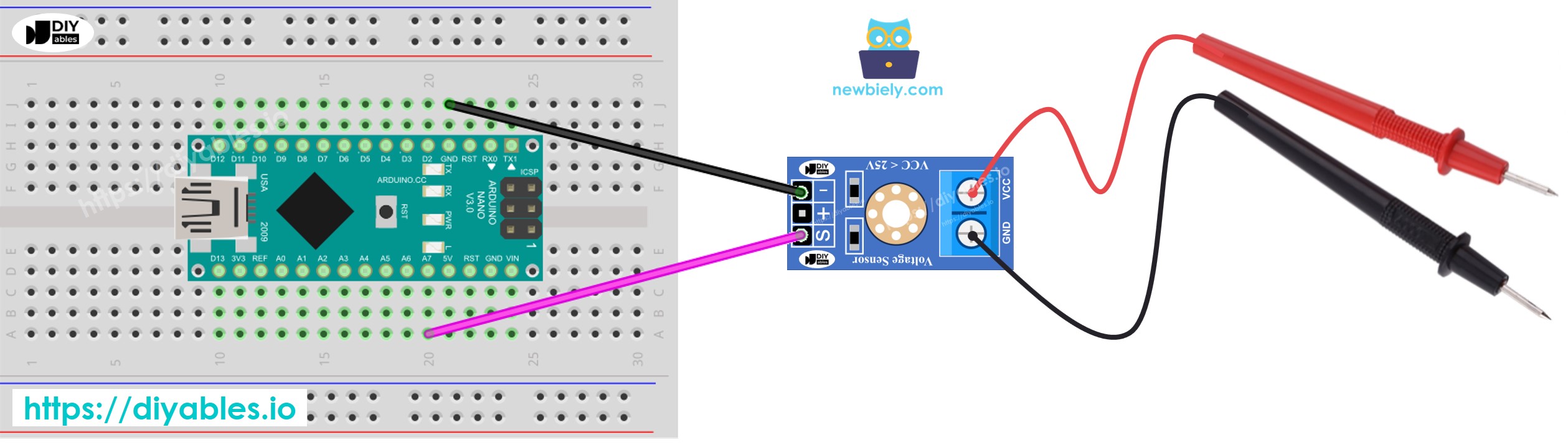
Measuring Voltage with a 3.3V Reference

To use this method, you need to set up both the hardware and the code. For the hardware, connect the AREF pin of the Arduino to 3.3V as shown in the diagram below.

The wiring diagram between Arduino Nano and measures voltage

This image is created using Fritzing. Click to enlarge image

Then, use the following code:

/* * This Arduino Nano code was developed by newbiely.com * * This Arduino Nano code is made available for public use without any restriction * * For comprehensive instructions and wiring diagrams, please visit: * https://newbiely.com/tutorials/arduino-nano/arduino-nano-measure-voltage */ #define ANALOG_IN_PIN A7 // The Arduino Nano pin connected to voltage sensor #define REF_VOLTAGE 3.3 #define ADC_RESOLUTION 1024.0 #define R1 30000.0 // resistor values in voltage sensor (in ohms) #define R2 7500.0 // resistor values in voltage sensor (in ohms) void setup() { Serial.begin(9600); analogReference(EXTERNAL); } void loop() { // read the analog input int adc_value = analogRead(ANALOG_IN_PIN); // determine voltage at adc input float voltage_adc = ((float)adc_value * REF_VOLTAGE) / ADC_RESOLUTION; // calculate voltage at the sensor input float voltage_in = voltage_adc * (R1 + R2) / R2; // print results to serial monitor to 2 decimal places Serial.print("Measured Voltage = "); Serial.println(voltage_in, 2); delay(500); }

Video Tutorial

Learn More

※ OUR MESSAGES

  • As freelancers, We are AVAILABLE for HIRE. See how to outsource your project to us
  • Please feel free to share the link of this tutorial. However, Please do not use our content on any other websites. We invested a lot of effort and time to create the content, please respect our work!