
ESP32 UNO - Multi-Function Shield
Want one board that gives your ESP32 Uno a display, keys, LEDs, a buzzer and two sensors at once? Press the multi-function shield onto the ESP32 Uno form board, add a short GPIO map to your sketch, and every part works from Arduino code. You get a 74HC595 4-digit 7-segment display, three push buttons, four LEDs, a beeper, a trimmer knob and an LM35 temperature sensor, with no breadboard and no loose wires.
By the end, you can:
- Plug the shield in and pass the correct GPIO numbers to the DIYables_MultiFuncShield library
- Print numbers, decimals and short words on the 4-digit 7-segment display
- Catch key presses and drive the LEDs and buzzer without delay()
- Read the trimmer value and the room temperature on the ESP32 Uno
The video walks through every example on this page, one after another.
Components You Need
Or you can buy the following kits:
| 1 | × | DIYables Sensor Kit (18 sensors/displays) |
Additionally, some of these links are for products from our own brand, DIYables .
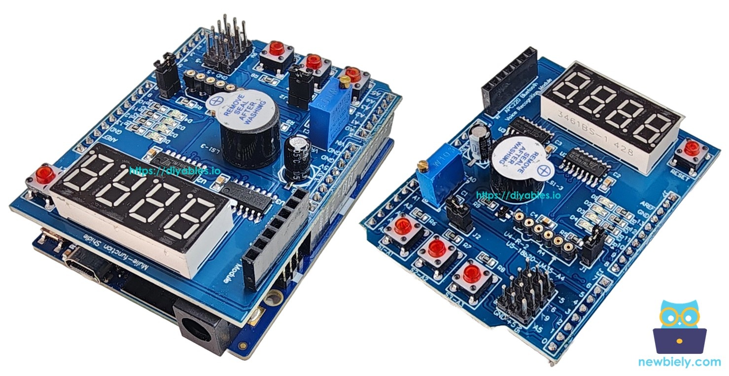
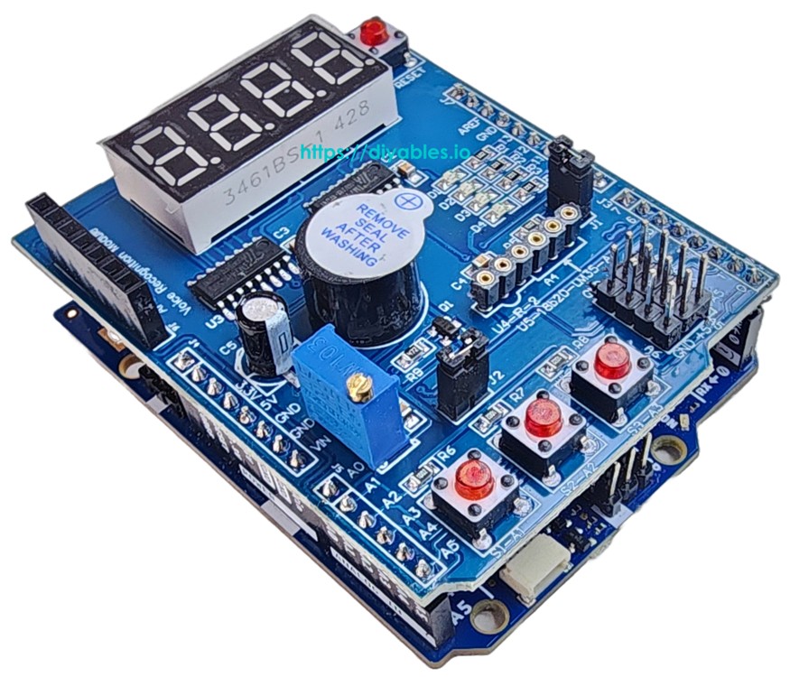
What Is on the Multi-Function Shield
After this part, you know each part on the shield, the Uno header it uses, and its GPIO on the ESP32 Uno.
| Part | Details | Logic |
|---|---|---|
| 4-digit 7-segment display | Fed by a 74HC595 shift register, so only 3 pins drive it. Shows numbers, decimals, letters A to Z and symbols like ° | Output only |
| Keys S1, S2, S3 | Pull-up resistor on the shield for each key. The library filters bounce | Active LOW (pressed = LOW) |
| LEDs D1 to D4 | On, off, toggle, blink, or all four together | Active LOW (LOW = lit) |
| Buzzer | Single beep, or a beep after a pause, without blocking | Active LOW |
| Trimmer potentiometer | Multi-turn type. Library returns a raw value or 0 to 100% | Analog, 0 to 4095 on the ESP32 Uno |
| LM35 temperature sensor | 10 mV per °C. Works only after jumper J1 comes off | Analog |
The shield keeps the classic Uno positions. Here is where each part lands and the GPIO number your ESP32 Uno code must use:
| Shield Part | Uno Header | ESP32 Uno GPIO |
|---|---|---|
| LED D1 | D13 | GPIO18 |
| LED D2 | D12 | GPIO19 |
| LED D3 | D11 | GPIO23 |
| LED D4 | D10 | GPIO5 |
| Key S1 | A1 | GPIO4 |
| Key S2 | A2 | GPIO35 |
| Key S3 | A3 | GPIO34 |
| Buzzer | D3 | GPIO25 |
| Display LATCH | D4 | GPIO17 |
| Display CLOCK | D7 | GPIO14 |
| Display DATA | D8 | GPIO12 |
| Trimmer | A0 | GPIO2 |
| LM35 sensor | A4 | GPIO36 |
Good to know: A4 on the ESP32 Uno is GPIO36, a plain analog input. The I2C lines are on the separate SDA (GPIO21) and SCL (GPIO22) header pins, so the LM35 never fights with an I2C module on this board.
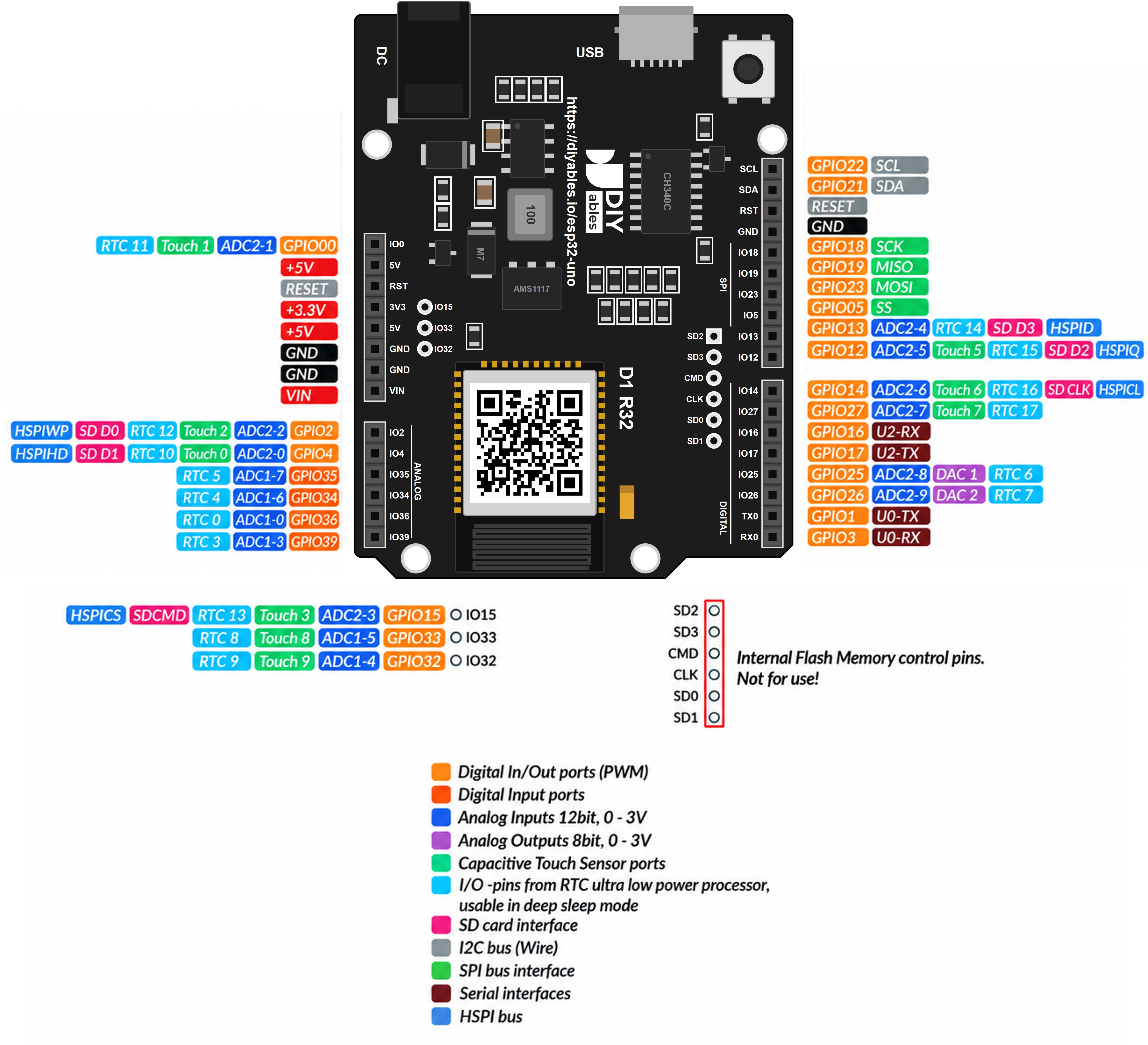
ESP32 Uno Pinout
Your sketch talks to GPIO numbers, not to the D and A labels printed on the headers. Keep this map open while you set up the pin list for the shield.
How to Connect
By the end of this part, the shield sits on the board and you know the three safety steps for 3.3V pins.
Line up the shield pins with the ESP32 Uno headers and press it down evenly. No jumper wires are needed.
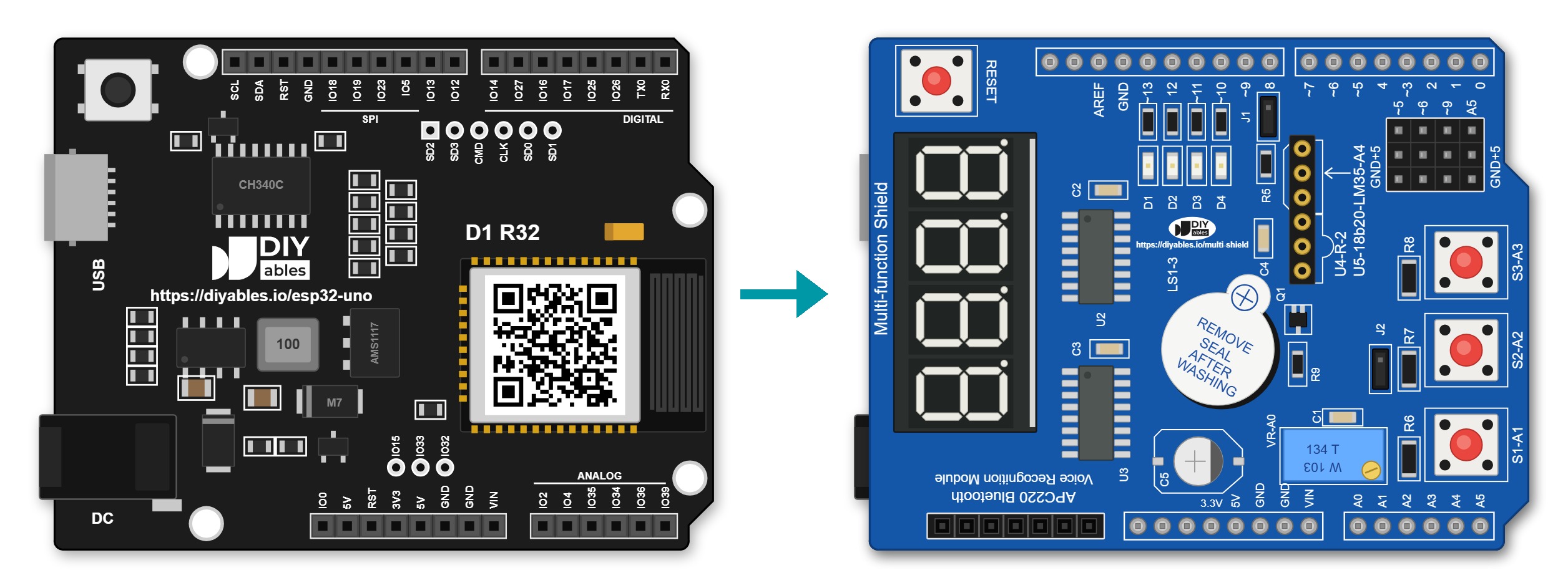
This image is created using Fritzing. Click to enlarge image
※ NOTE THAT:
The picture shows only how the shield plugs into the ESP32 Uno. The three 15 kΩ resistors from the warning below sit under the shield, so you cannot see them in the picture. Turn the trimmer to 0 before you stack the shield.
| Shield Part | ESP32 Uno Pin |
|---|---|
| 5V | 5V |
| GND | GND |
| LED D1 | D13 (GPIO18) |
| LED D2 | D12 (GPIO19) |
| LED D3 | D11 (GPIO23) |
| LED D4 | D10 (GPIO5) |
| Key S1 | A1 (GPIO4) |
| Key S2 | A2 (GPIO35) |
| Key S3 | A3 (GPIO34) |
| Buzzer | D3 (GPIO25) |
| Display LATCH | D4 (GPIO17) |
| Display CLOCK | D7 (GPIO14) |
| Display DATA | D8 (GPIO12) |
| Trimmer | A0 (GPIO2) |
| LM35 sensor | A4 (GPIO36) |
WARNING
ESP32 Uno pins are 3.3V only. The shield, however, runs on 5V, and two parts push voltage back into the board. (1) The trimmer is wired between 5V and GND, so its wiper on A0 (GPIO2) can reach 5V. Before you stack the shield, spin the trimmer screw about 20 turns counter-clockwise to park it at the 0V end, and later stop turning as soon as the Serial Monitor shows 100%. (2) The keys on A1, A2 and A3 have pull-ups to 5V (usually 10 kΩ). For long-term use, solder a 15 kΩ resistor from each of these three pins to GND under the shield. That divider holds an idle key line near 3.0V, which still reads HIGH.
WARNING
Boot strapping pins are under three shield parts. D8 (GPIO12) carries the display DATA line and must be LOW at boot. The 74HC595 input does not pull it, so this is normally fine. D10 (GPIO5) carries LED D4, and its LED pulls the line high, which is the state GPIO5 wants at boot. A0 (GPIO2) carries the trimmer. If the trimmer sits at the high end when you upload, the board can refuse to enter download mode. Keep the trimmer near 0% while you upload code.
WARNING
Pull jumper J1 off the shield before you use the LM35. On most shield versions, J1 connects a pull-up resistor (meant for a DS18B20) to the A4 line. With J1 on, A4 (GPIO36) is pulled toward 5V and the temperature is wrong.
Good to know: A2, A3 and A4 (GPIO35, GPIO34, GPIO36) are input only and have no internal pull-up. That is fine here: the keys use the pull-ups on the shield, and the LM35 drives its own output.
Install the DIYables_MultiFuncShield Library
After this part, the library that handles the display refresh, key debounce, LED blinking and buzzer timing is ready in your IDE.
- Connect the board to your computer with the USB Type-C cable.
- Choose the board in Arduino IDE: pick ESP32 Dev Module (esp32 by Espressif Systems core) and the CH340 COM port.
- Open the Library Manager with the Libraries icon on the left side.
- Search for "DIYables_MultiFuncShield" and find the entry from DIYables.
- Click Install.
- Search for DIYables_MultiFuncShield created by DIYables.io and click the Install button.
The library needs nothing else. It also detects the ESP32 Uno by itself and uses a 12-bit ADC with a 3.3V reference.
The Starting Frame for Every Sketch
By the end of this part, you know the one change every ESP32 Uno sketch for this shield needs: a GPIO pin list.
The library ships with Uno pin numbers (13, 12, 11, 10 and so on). On the ESP32 Uno those numbers mean other GPIOs, and GPIO10 and GPIO11 are even wired to the flash chip. So you fill an MFS_Pins list with the real GPIOs and build your own shield object from it.
| Code Part | What It Does |
|---|---|
| MFS_Pins esp32UnoPins() | Returns the 13 GPIO numbers of the shield parts on the ESP32 Uno |
| DIYables_MultiFuncShield shield(...) | Builds a shield object that uses those GPIOs |
| shield.begin() | Sets the pin modes and clears the display |
| shield.loop() | Multiplexes the digits, debounces the keys, times LED blinks and beeps |
Call shield.loop() on every pass of loop() and keep long delay() calls out of it, or the display starts to flicker.
WARNING
The library already defines a global object named MFS that holds the Uno pin numbers. Never name your own object MFS (the build fails with "multiple definition of MFS"), and never call MFS.begin() on the ESP32 Uno. It would set GPIO10 and GPIO11 as outputs, and those pins belong to the flash chip, so the board crashes and restarts.
7-Segment Display Example
After this part, the display shows a new format every 3 seconds.
Upload and Test
- First time with this board? Set it up with ESP32 Uno - Getting Started before you continue.
- Build the circuit: park the trimmer at 0V, remove J1 if you plan to use the LM35, then press the shield onto the ESP32 Uno.
- Plug in the USB Type-C cable between the ESP32 Uno and your computer.
- Select the board in Arduino IDE: pick ESP32 Dev Module and the COM port of the board (CH340).
- Paste the sketch above into a new Arduino IDE window.
- Click Upload and wait for "Done uploading".
- Pro tip: if the upload stops at "Connecting...", hold the BOOT button until the dots stop, and check that the trimmer is still near 0%.
The display cycles through seven views, one every 3 seconds:
| Step | Display Shows | Call Used |
|---|---|---|
| 1 | 42 | print(42) |
| 2 | 0042 | print(42, true) |
| 3 | 3.14 | print(3.14, 2) |
| 4 | HELP | print("HELP") |
| 5 | Ab.Cd | print("Ab.Cd") |
| 6 | 25°C | setNumber + setChar + show |
| 7 | ---- | print("----") |
Display Methods
| Method | Result | Example Call | ||
|---|---|---|---|---|
| print(int) | A whole number | shield.display.print(42) | ||
| print(int, true) | A whole number with zeros in front | shield.display.print(42, true) → 0042 | ||
| print(float, dp) | A decimal number with dp digits after the dot | shield.display.print(3.14, 2) | ||
| print(text) | A short word (A-Z, 0-9, -, _) | shield.display.print("HELP") | ||
| setNumber(pos, val) | One digit at position 1 to 4 | shield.display.setNumber(1, 5) | ||
| setChar(pos, ch) | One letter at a position | shield.display.setChar(2, 'A') | ||
| setChar(pos, SegChars) | One special symbol at a position | shield.display.setChar(3, SegChars | DEGREE) | |
| setDot(pos) | The dot at a position | shield.display.setDot(2) | ||
| clear() | Turns off every segment | shield.display.clear() | ||
| show() | Sends hand-built content to the display | shield.display.show() |
Each print() call runs show() by itself. For a hand-built screen, start with clear(), place the digits with setNumber(), setChar() or setDot(), and finish with show().
Good to know: SegChars holds six symbols: DASH, UNDERSCORE, C, E, F and DEGREE.
LED Example
After this part, the four LEDs light up in turn, go dark, and then blink together.
Upload and Test
- Upload the sketch.
- Open the Serial Monitor at 9600 baud to follow each stage.
- Watch the LEDs: they switch on one by one every half second, switch off the same way, LED 1 blinks alone for 3 seconds, and then all four blink.
LED Methods
| Method | Result |
|---|---|
| turnON() | Lights the LED |
| turnOFF() | Turns the LED off |
| toggle() | Swaps between on and off |
| blink(interval) | Blinks with the same on and off time |
| blink(onTime, offTime) | Blinks with separate on and off times |
| isOn() | true while the LED is lit |
Group calls for all four LEDs at once:
| Method | Result |
|---|---|
| allLedsOn() | Lights all four LEDs |
| allLedsOff() | Turns all four LEDs off |
| allLedsBlink(interval) | Blinks all four in step |
| allLedsBlink(onTime, offTime) | Blinks all four with custom timing |
Use shield.led1 to shield.led4, or the numbered form shield.led(1) to shield.led(4). All LEDs are active LOW.
Good to know: the LEDs connect to 5V on the shield. A 3.3V HIGH may leave a faint glow on some units. That is normal and does not harm the board.
Buzzer Example
After this part, the buzzer gives a short beep every 2 seconds.
Upload and Test
- Upload the sketch.
- Listen: a 100 ms beep sounds every 2 seconds.
- Change the sound by editing beep(100) to a longer time, like beep(400).
Buzzer Methods
| Method | Result |
|---|---|
| beep(ms) | Sounds for ms milliseconds |
| beep(ms, delayMs) | Waits delayMs, then sounds for ms |
| stop() | Silences the buzzer at once |
| isBeeping() | true while the buzzer is on |
Potentiometer Example
After this part, the Serial Monitor shows the trimmer as a raw 12-bit value and as a percent.
Good to know: the sketch calls analogSetAttenuation(ADC_11db) in setup(). The 11 dB attenuation lets the ESP32 Uno analog pin read the full range, from 0V up to about 3.3V. With a narrower range, the value hits 4095 too early and the readings look wrong.
Upload and Test
- Upload the sketch.
- Open the Serial Monitor at 9600 baud.
- Turn the trimmer screw clockwise with a small screwdriver. It is multi-turn, so many turns move it from 0% to 100%.
- Stop at 100%. Past that point the wiper goes above 3.3V. Turn back a little until the value drops.
Potentiometer Methods
| Method | Returns | Result |
|---|---|---|
| readPot() | int | Raw ADC value, 0 to 4095 on the 12-bit ESP32 Uno ADC |
| readPotPercent() | float | The same value scaled to 0.0 to 100.0 |
LM35 Temperature Example
After this part, the room temperature in Celsius shows on the display and on the Serial Monitor.
Before you start: take jumper J1 off the shield. It ties a pull-up to the A4 line, and the LM35 reading is wrong while it is on.
Upload and Test
- Remove jumper J1 from the shield.
- Upload the sketch.
- Open the Serial Monitor at 9600 baud.
- Hold the LM35 between two fingers for a few seconds and watch the number climb on both the display and the monitor.
The library averages the last 4 readings to smooth the value. The first reading fills the whole buffer, so you see a steady number from the start.
Good to know: the LM35 output is only about 0.24V at 24 °C. The ESP32 Uno ADC is less exact near 0V, so a reading can be 1 to 2 °C off. Check against a known thermometer and add a small offset in code if needed.
Full Demo Video
See the ESP32 Uno build in action in the video below.
ESP32 Uno vs UNO R4 for This Project
This table lists what changes when you move the shield from an UNO R4 to the ESP32 Uno.
| Item | Arduino UNO R4 | ESP32 Uno |
|---|---|---|
| Logic voltage | 5V | 3.3V (pins are not 5V tolerant) |
| Shield object | Built-in MFS with default pins | Own shield object with an MFS_Pins GPIO list |
| Display pins | D4, D7, D8 | GPIO17, GPIO14, GPIO12 |
| Trimmer and LM35 pins | A0 and A4 | GPIO2 and GPIO36 |
| ADC range | 0 to 16383 (14-bit) | 0 to 4095 (12-bit) |
| Extra code line | None | analogSetAttenuation(ADC_11db) in the analog sketches |
| Arduino IDE board | Arduino UNO R4 WiFi or Minima | ESP32 Dev Module |
The shield plugs in at the same positions, so no rewiring is needed. Watch the 5V trimmer and the 5V key pull-ups, and always use the GPIO pin list instead of MFS.begin().
Platform Support
The DIYables_MultiFuncShield library is built for every Arduino architecture (architectures=*). On the ESP32 Uno it picks the 12-bit ADC and the 3.3V reference by itself. The one thing you add is the esp32UnoPins() list shown in each sketch above.
Go Wireless: See the Shield Temperature on Your Phone
After this part, you have an idea for taking the shield readings off the desk and onto your phone.
The ESP32 Uno has WiFi and Bluetooth (Classic and BLE), so the LM35 reading can go to a web page or a phone app while the 7-segment display still shows it locally. The LM35 sits on A4 (GPIO36), an ADC1 pin, so it keeps working with WiFi on. The trimmer on A0 (GPIO2) is an ADC2 pin and cannot be read while WiFi runs, so use Bluetooth if you want the knob value too. You can also switch the four LEDs from your phone.
Troubleshooting
| Problem | Possible Cause | Solution |
|---|---|---|
| No COM port appears in Arduino IDE | CH340 driver missing or a charge-only USB cable | Install the CH340 driver and use a USB cable that carries data |
| Upload ends with "Failed to connect" or "Waiting for download" | Board did not enter download mode, or the trimmer holds A0 (GPIO2) high | Hold BOOT while the upload starts, and turn the trimmer back toward 0% |
| Board does not boot or upload with the shield on | A boot strapping pin (D8 GPIO12, D10 GPIO5 or A0 GPIO2) is pulled the wrong way | Unplug the shield while uploading, then plug it back and press RST |
| Board resets again and again after upload | Sketch calls MFS.begin(), which touches the flash pins GPIO10 and GPIO11 | Use the esp32UnoPins() list and the shield object |
| Build error "multiple definition of MFS" | Your object has the same name as the library object | Rename it to shield and change every MFS. call |
| Display stays blank or shows random segments | Shield not pressed fully down, or 3.3V signals are weak for the 5V 74HC595 | Seat the shield firmly, check 5V and GND, and use a strong USB port |
| Key S2 or S3 never reacts | Pull-up missing on GPIO35 or GPIO34, or wrong GPIO in the list | Check that the shield pull-ups are fitted and that button2 is 35 and button3 is 34 |
| Trimmer reads 100% for many turns | Wiper is above 3.3V, so the ADC is full | Turn it back until the value drops and do not turn further |
| Temperature reads far too high | Jumper J1 is still on | Remove J1 and press RST |
| Trimmer reads 0 or stays fixed in a WiFi sketch | A0 (GPIO2) is an ADC2 pin, blocked while WiFi is on | Use Bluetooth instead, or wire a separate knob to GPIO32 or GPIO33 |
FAQ
Does the multi-function shield fit the ESP32 Uno form board?
Yes. The ESP32 Uno uses the Uno header layout, so the shield presses on at the same spots. What changes is the code: you give the library a GPIO list with MFS_Pins, because the Uno numbers point to different pins on this board.
Why do I need my own shield object instead of MFS?
The ready-made MFS object stores the Uno pin numbers. On the ESP32 Uno, pins 10 and 11 are flash pins, so MFS.begin() would crash the board. Your own object, built from esp32UnoPins(), uses the right GPIOs.
Can the 5V shield damage the 3.3V pins?
Most parts only receive signals, so they are safe. The trimmer and the key pull-ups are tied to 5V and can push more than 3.3V into A0 to A3. Park the trimmer at 0V, stop at 100%, and add 15 kΩ resistors from A1, A2 and A3 to GND for long-term use.
What raw range does the trimmer give on the ESP32 Uno?
It gives 0 to 4095, because the ESP32 Uno ADC is 12-bit. The UNO R4 gives 0 to 16383 with its 14-bit ADC. readPotPercent() always returns 0 to 100%, so code that uses the percent works on both boards.
Why does the code call analogSetAttenuation(ADC_11db)?
It sets the ESP32 Uno ADC input range to about 0 to 3.3V, so the full trimmer and LM35 signal maps to 0 to 4095. With a smaller range, the readings saturate early. The UNO R4 sketch does not have this line, because only ESP32 chips need it. Keep every analog input at 3.3V or less.
How accurate is the LM35 on this shield?
The LM35 itself is good to about ±0.5 °C at room temperature. The ESP32 Uno ADC adds some error at low voltages, so expect 1 to 2 °C. Compare once with a trusted thermometer and add a fixed offset in your code.
Why do A2 and A3 need the shield's pull-ups?
A2 (GPIO35) and A3 (GPIO34) are input-only pins with no internal pull-up resistor. The INPUT_PULLUP mode has no effect on them. The pull-up resistors on the shield keep the keys at HIGH until you press them.
Are D8, D10 and A0 safe to use on the ESP32 Uno?
They are boot strapping pins (GPIO12, GPIO5, GPIO2). With this shield they normally boot fine, because the display input does not pull D8 and the LED keeps D10 high. A0 is the one to watch: keep the trimmer low during uploads.
Can I use the trimmer and WiFi in the same sketch?
Not on A0. A0 (GPIO2) and A1 (GPIO4) are ADC2 pins, and ADC2 cannot be read while WiFi is on. The keys on A1 still work, because they are digital reads. For an analog knob in a WiFi project, move it to A2 to A5 (GPIO35, 34, 36, 39) or GPIO32/33 and change the pin in code.
Do I need a driver to upload code to the ESP32 Uno?
The board uses a CH340 USB-to-serial chip. Windows and macOS often need the CH340 driver once. After that, the board appears as a COM port in Arduino IDE.
What if my project needs more pins than the shield leaves free?
The shield covers most Uno headers, but the ESP32 Uno has a few extra holes near the power header: GPIO32 and GPIO33 (I/O, PWM, analog on ADC1, so they work with WiFi on) and GPIO15 (I/O, PWM, analog on ADC2). Solder pin headers to them and write the GPIO number in code. For an extra sensor in a WiFi version of this project, use GPIO32 or GPIO33. Two warnings: GPIO15 and GPIO0 (the IO0 pin at the unused Uno NC position) are boot strapping pins, and a wrong connection can stop the board from booting or uploading code, so try GPIO32/33 first. Also never use the six holes under the digital header (SD0 to SD3, CMD, CLK = GPIO6 to GPIO11). They connect to the flash chip, and using them crashes the board.
How to Connect Other Components
The Multi-Function Shield covers all the pins of the ESP32 Uno, and it has no female headers on top. So how can you connect other components, such as sensors, relays or motors, to the ESP32 Uno?
The answer is simple: put a Proto Screw Terminal Block Shield or a Screw Shield V2 between the ESP32 Uno and the Multi-Function Shield.
- Step 1: Stack the Proto Screw Terminal Block Shield or the Screw Shield V2 on the ESP32 Uno.
- Step 2: Stack the Multi-Function Shield on the screw shield.
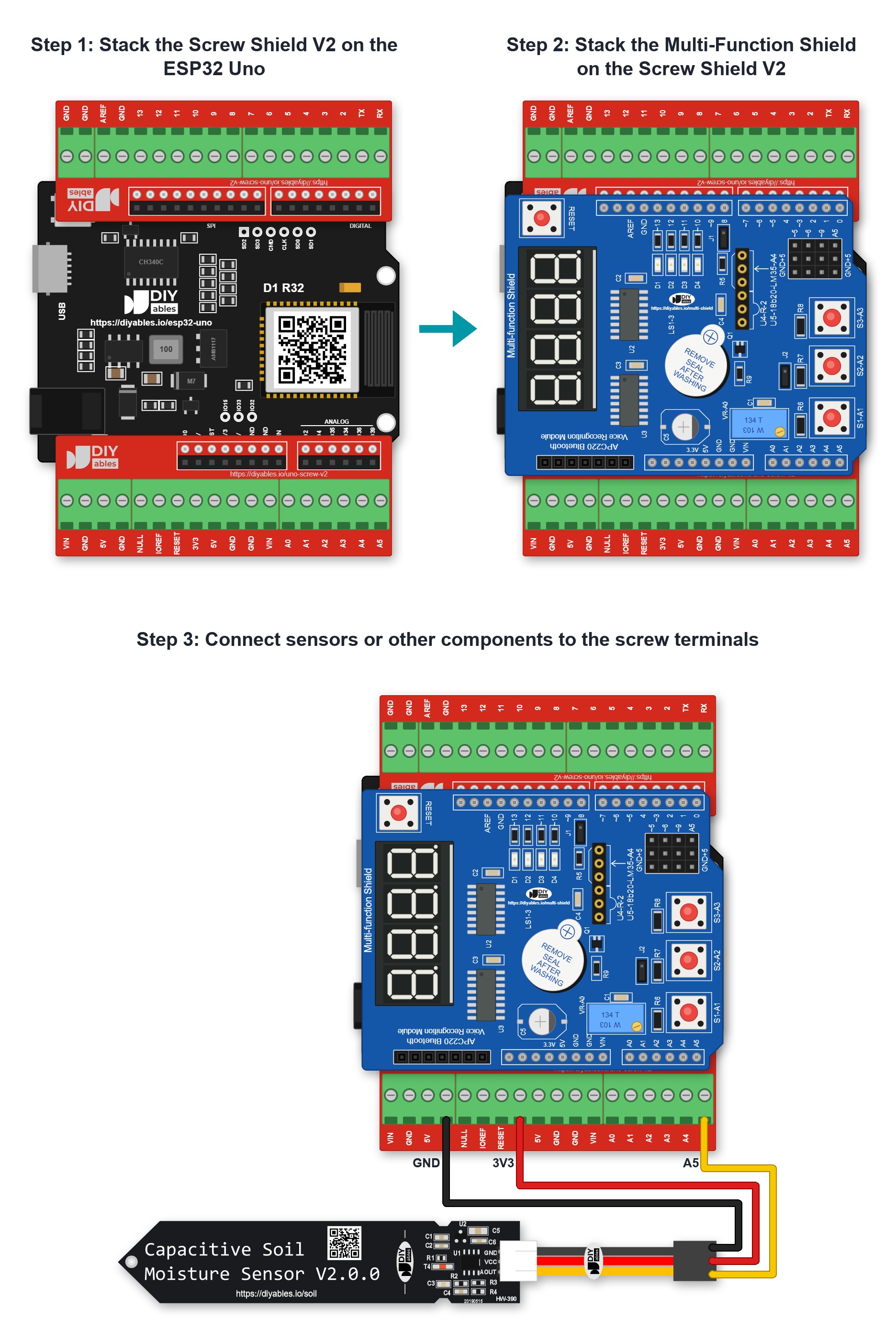
The screw shield has a screw terminal for each pin. It lets you connect the ESP32 Uno to other components. Do not use the pins that the Multi-Function Shield already uses: D3, D4, D7, D8, D10 to D13 and A0 to A3, and also A4 when you use the LM35 sensor. The free pins are D2, D5, D6, D9 and A5. D2 is free when the U4 socket (for an IR receiver) is empty. On the ESP32 Uno, these free pins are D2 (GPIO26), D5 (GPIO16), D6 (GPIO27), D9 (GPIO13) and A5 (GPIO39, input only). Every screw terminal goes straight to a 3.3V pin, so keep each signal at 3.3V or less.