Arduino UNO R4 - DIYables Bluetooth App Digital Pins

Overview

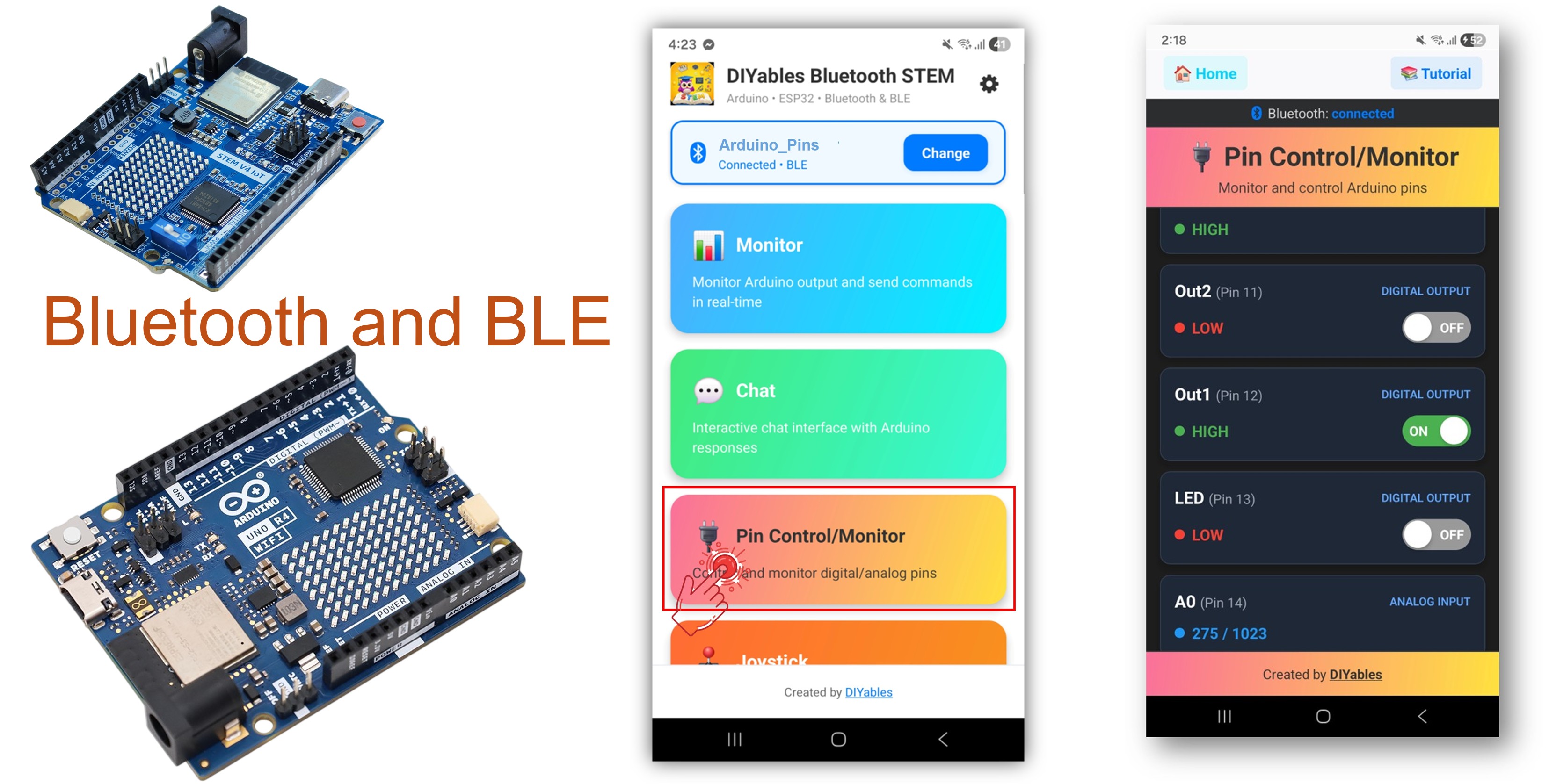
The Bluetooth Digital Pins example provides remote GPIO pin control and monitoring accessible through the DIYables Bluetooth STEM app. Designed for Arduino UNO R4 WiFi using BLE (Bluetooth Low Energy) to control output pins and monitor input pins wirelessly from your smartphone. Perfect for relay control, button monitoring, LED switching, and any application requiring remote pin access.

Note: The Arduino UNO R4 WiFi only supports BLE (Bluetooth Low Energy). It does not support Classic Bluetooth. The DIYables Bluetooth App supports both BLE and Classic Bluetooth on Android, and BLE on iOS. Since this board uses BLE, the app works on both Android and iOS.

Arduino UNO R4 WiFi Bluetooth Digital Pins Example - GPIO Pin Control via BLE Tutorial

Features

  • Output Control: Set digital pins HIGH/LOW remotely
  • Input Monitoring: Read digital and analog pin states
  • Named Pins: Assign friendly names to each pin (e.g., "LED", "Relay")
  • Real-Time Updates: Push pin state changes to the app
  • Up to 16 Pins: Control multiple pins simultaneously
  • Works on Android & iOS: BLE is supported on both platforms
  • No Pairing Required: BLE auto-connects without manual pairing

Arduino UNO R4 WiFi Code

Detailed Instructions

Follow these instructions step by step:

  • If this is your first time using the Arduino UNO R4 WiFi, refer to the Arduino UNO R4 WiFi getting started guide.
  • Connect the Arduino UNO R4 WiFi board to your computer using a USB cable.
  • Launch the Arduino IDE on your computer.
  • Select Arduino UNO R4 WiFi board and the appropriate COM port.
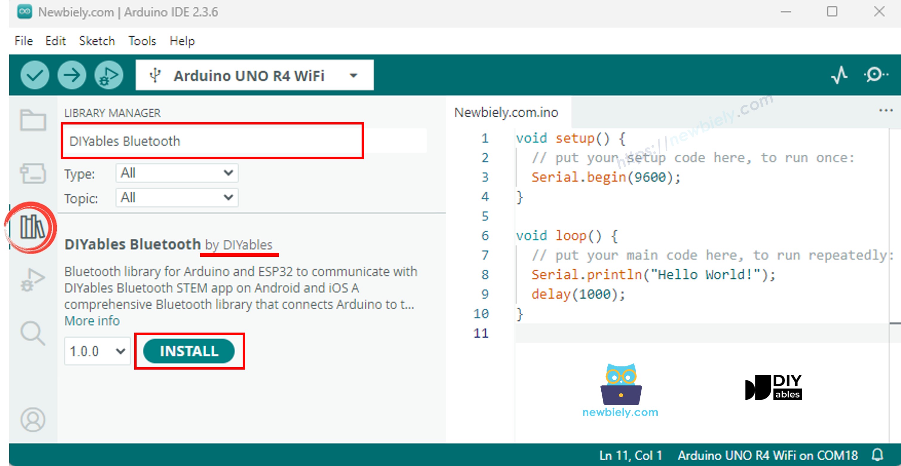
  • Navigate to the Libraries icon on the left bar of the Arduino IDE.
  • Search "DIYables Bluetooth", then find the DIYables Bluetooth library by DIYables
  • Click Install button to install the library.
Arduino UNO R4 DIYables Bluetooth library
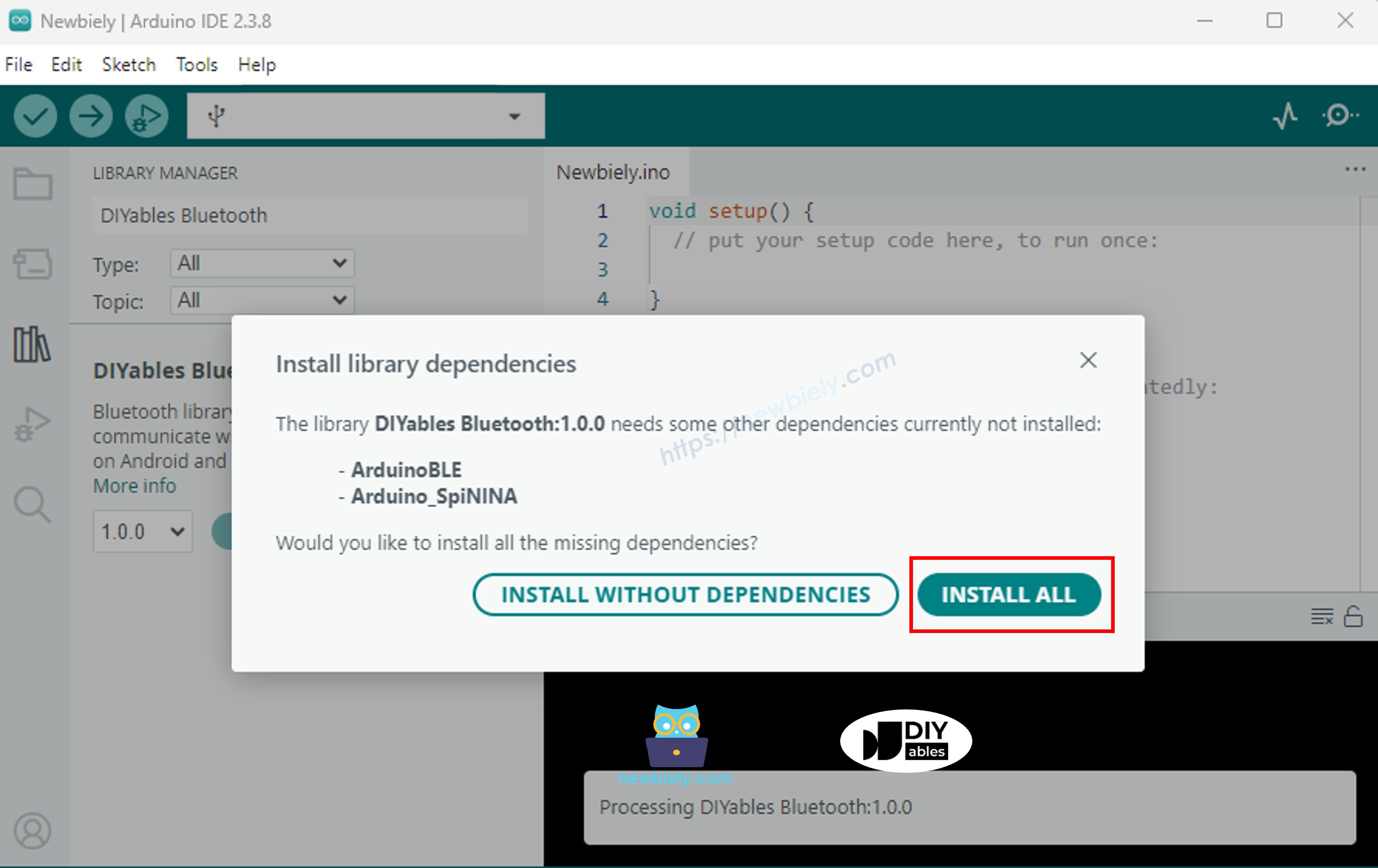
  • You will be asked for installing some other library dependencies
  • Click Install All button to install all library dependencies.
Arduino UNO R4 DIYables Bluetooth dependency

BLE Code

  • On Arduino IDE, Go to File Examples DIYables Bluetooth ArduinoBLE_PinControl example, or copy the above code and paste it to the editor of Arduino IDE
/* * DIYables Bluetooth Library - Bluetooth Pin Control/Monitor Example * Works with DIYables Bluetooth STEM app on Android and iOS * * This example demonstrates the Bluetooth Pin Control/Monitor feature: * - Control digital output pins via Bluetooth * - Monitor digital input pins * - Monitor analog input pins * - Configure pin modes (INPUT/OUTPUT) * * Compatible Boards: * - Arduino UNO R4 WiFi * - Arduino Nano 33 BLE / BLE Sense * - Arduino Nano 33 IoT * - Arduino MKR WiFi 1010 * - Arduino Nano RP2040 Connect * - Any board supporting the ArduinoBLE library * * Setup: * 1. Upload the sketch to your Arduino * 2. Open Serial Monitor to see connection status * 3. Use DIYables Bluetooth App to connect and control pins * * Tutorial: https://diyables.io/bluetooth-app * Author: DIYables */ #include <DIYables_BluetoothServer.h> #include <DIYables_BluetoothPinControl.h> #include <platforms/DIYables_ArduinoBLE.h> // BLE Configuration const char* DEVICE_NAME = "Arduino_Pins"; const char* SERVICE_UUID = "19B10000-E8F2-537E-4F6C-D104768A1214"; const char* TX_UUID = "19B10001-E8F2-537E-4F6C-D104768A1214"; const char* RX_UUID = "19B10002-E8F2-537E-4F6C-D104768A1214"; // Create Bluetooth instances DIYables_ArduinoBLE bluetooth(DEVICE_NAME, SERVICE_UUID, TX_UUID, RX_UUID); DIYables_BluetoothServer bluetoothServer(bluetooth); // Create Pin Control/Monitor app instance DIYables_BluetoothPinControl bluetoothPins; // Pin configuration const int LED_PIN = 13; const int OUTPUT_PIN_1 = 12; const int OUTPUT_PIN_2 = 11; const int INPUT_PIN_1 = 7; const int INPUT_PIN_2 = 6; const int ANALOG_PIN_1 = A0; const int ANALOG_PIN_2 = A1; void setup() { Serial.begin(9600); while (!Serial); Serial.println("DIYables Bluetooth - Pin Control/Monitor Example"); // Initialize pins pinMode(LED_PIN, OUTPUT); pinMode(OUTPUT_PIN_1, OUTPUT); pinMode(OUTPUT_PIN_2, OUTPUT); pinMode(INPUT_PIN_1, INPUT_PULLUP); pinMode(INPUT_PIN_2, INPUT_PULLUP); // Initialize Bluetooth server with platform-specific implementation bluetoothServer.begin(); // Add digital pins app to server bluetoothServer.addApp(&bluetoothPins); // Configure which pins are accessible via Bluetooth with custom names bluetoothPins.enablePin(LED_PIN, BT_PIN_OUTPUT, "LED"); bluetoothPins.enablePin(OUTPUT_PIN_1, BT_PIN_OUTPUT, "Out1"); bluetoothPins.enablePin(OUTPUT_PIN_2, BT_PIN_OUTPUT, "Out2"); bluetoothPins.enablePin(INPUT_PIN_1, BT_PIN_INPUT, "Btn1"); bluetoothPins.enablePin(INPUT_PIN_2, BT_PIN_INPUT, "Btn2"); bluetoothPins.enablePin(ANALOG_PIN_1, BT_PIN_INPUT, "A0"); bluetoothPins.enablePin(ANALOG_PIN_2, BT_PIN_INPUT, "A1"); // Set up connection event callbacks bluetoothServer.setOnConnected([]() { Serial.println("Bluetooth connected!"); }); bluetoothServer.setOnDisconnected([]() { Serial.println("Bluetooth disconnected!"); }); // Set up callback for pin write commands bluetoothPins.onPinWrite([](int pin, int state) { digitalWrite(pin, state); Serial.print("Pin "); Serial.print(pin); Serial.print(" set to "); Serial.println(state ? "HIGH" : "LOW"); }); // Set up callback for pin read commands bluetoothPins.onPinRead([](int pin) -> int { // Read analog pins with analogRead, digital pins with digitalRead int state; if (pin == ANALOG_PIN_1 || pin == ANALOG_PIN_2) { state = analogRead(pin); Serial.print("Analog pin "); Serial.print(pin); Serial.print(" read: "); Serial.println(state); } else { state = digitalRead(pin); Serial.print("Digital pin "); Serial.print(pin); Serial.print(" read: "); Serial.println(state ? "HIGH" : "LOW"); } return state; }); // Set up callback for pin mode changes bluetoothPins.onPinModeChange([](int pin, int mode) { pinMode(pin, mode == BT_PIN_OUTPUT ? OUTPUT : INPUT_PULLUP); Serial.print("Pin "); Serial.print(pin); Serial.print(" mode changed to "); Serial.println(mode == BT_PIN_OUTPUT ? "OUTPUT" : "INPUT"); }); Serial.println("Waiting for Bluetooth connection..."); Serial.print("Enabled pins: "); Serial.println(bluetoothPins.getEnabledPinCount()); } void loop() { // Handle Bluetooth server communications bluetoothServer.loop(); // Optional: Monitor input pins and send updates static unsigned long lastInputCheck = 0; static int lastInputState1 = HIGH; static int lastInputState2 = HIGH; static int lastAnalogState1 = 0; static int lastAnalogState2 = 0; if (millis() - lastInputCheck >= 100) { lastInputCheck = millis(); // Check digital input pin 1 int currentState1 = digitalRead(INPUT_PIN_1); if (currentState1 != lastInputState1) { lastInputState1 = currentState1; bluetoothPins.updatePinState(INPUT_PIN_1, currentState1); Serial.print("Input pin "); Serial.print(INPUT_PIN_1); Serial.print(" changed to "); Serial.println(currentState1 ? "HIGH" : "LOW"); } // Check digital input pin 2 int currentState2 = digitalRead(INPUT_PIN_2); if (currentState2 != lastInputState2) { lastInputState2 = currentState2; bluetoothPins.updatePinState(INPUT_PIN_2, currentState2); Serial.print("Input pin "); Serial.print(INPUT_PIN_2); Serial.print(" changed to "); Serial.println(currentState2 ? "HIGH" : "LOW"); } // Check analog input 1 (send update if changed by more than 10) int currentAnalog1 = analogRead(ANALOG_PIN_1); if (abs(currentAnalog1 - lastAnalogState1) > 10) { lastAnalogState1 = currentAnalog1; bluetoothPins.updatePinState(ANALOG_PIN_1, currentAnalog1); Serial.print("Analog pin "); Serial.print(ANALOG_PIN_1); Serial.print(" changed to "); Serial.println(currentAnalog1); } // Check analog input 2 (send update if changed by more than 10) int currentAnalog2 = analogRead(ANALOG_PIN_2); if (abs(currentAnalog2 - lastAnalogState2) > 10) { lastAnalogState2 = currentAnalog2; bluetoothPins.updatePinState(ANALOG_PIN_2, currentAnalog2); Serial.print("Analog pin "); Serial.print(ANALOG_PIN_2); Serial.print(" changed to "); Serial.println(currentAnalog2); } } delay(10); }
  • Click Upload button on Arduino IDE to upload code to Arduino UNO R4 WiFi
  • Open the Serial Monitor
  • Check out the result on Serial Monitor. It looks like the below:
COM6
Send
DIYables Bluetooth - Pin Control/Monitor Example Waiting for Bluetooth connection... Enabled pins: 7
Autoscroll Show timestamp
Clear output
9600 baud  
Newline  

Mobile App

  • Install the DIYables Bluetooth App on your smartphone: Android | iOS

Note: The DIYables Bluetooth App supports both BLE and Classic Bluetooth on Android, and BLE on iOS. Since the Arduino UNO R4 WiFi uses BLE, the app works on both Android and iOS. No manual pairing is needed for BLE — just scan and connect.

  • Open the DIYables Bluetooth App
  • When opening the app for the first time, it will ask for permissions. Please grant the following:
    • Nearby Devices permission (Android 12+) / Bluetooth permission (iOS) - required to scan and connect to Bluetooth devices
    • Location permission (Android 11 and below only) - required by older Android versions to scan for BLE devices
  • Make sure Bluetooth is turned on on your phone
  • On the home screen, tap the Connect button. The app will scan for BLE devices.
DIYables Bluetooth App - Home Screen with Scan Button
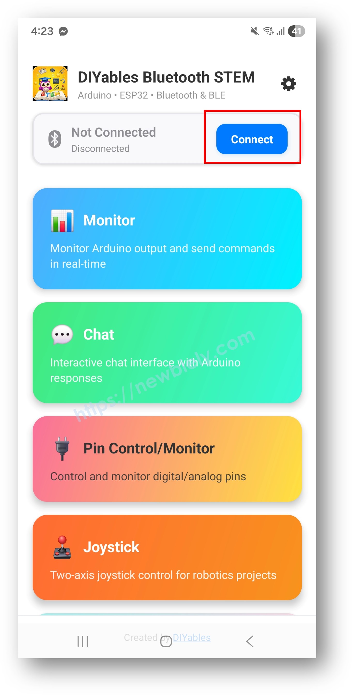
  • Find and tap "Arduino_Pins" in the scan results to connect.
  • Once connected, the app automatically goes back to the home screen. Select the Digital Pins app from the app menu.
DIYables Bluetooth App - Home Screen with Digital Pins App

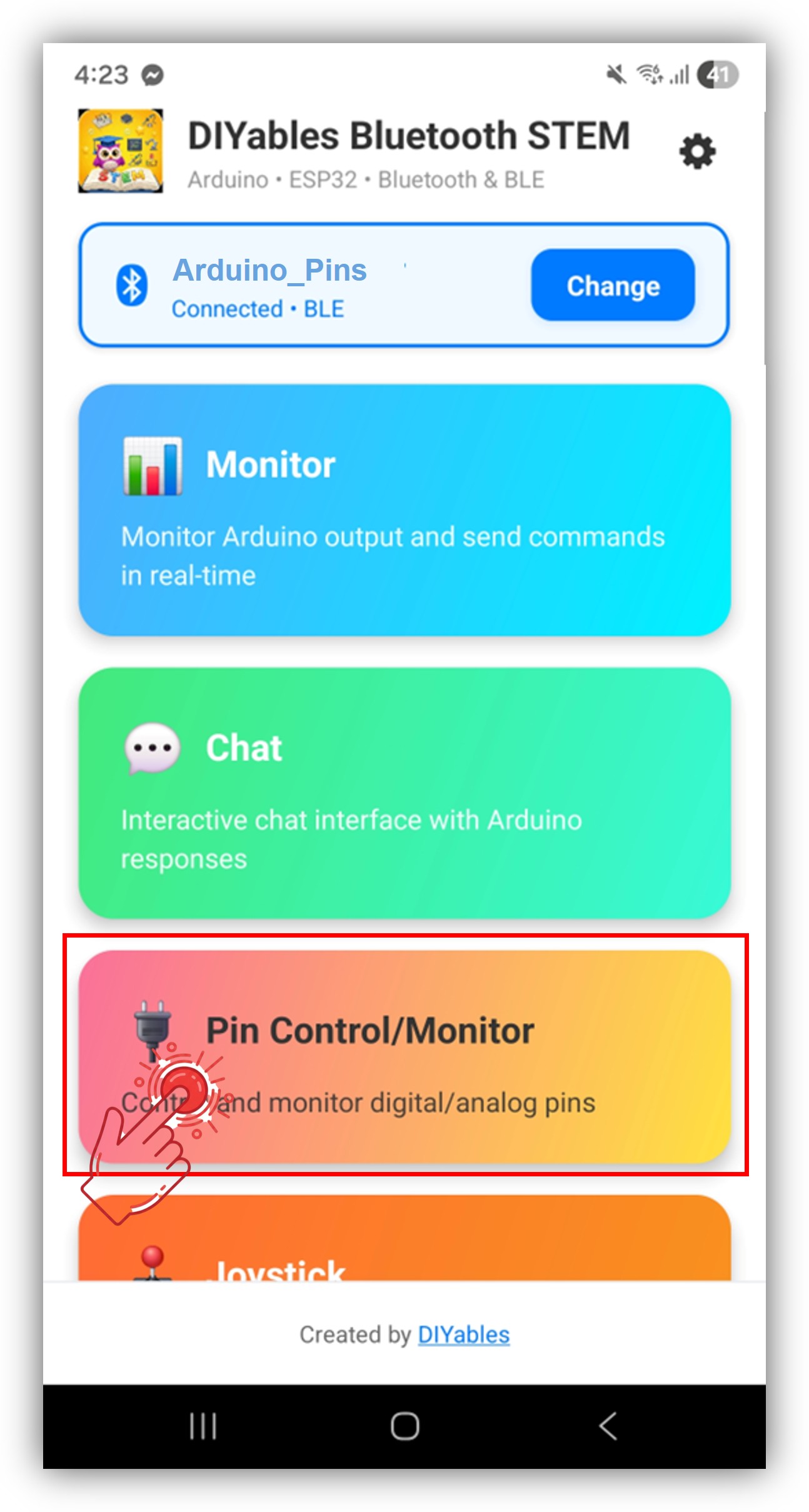
Note: You can tap the settings icon on the home screen to hide/show apps on the home screen. For more details, see the DIYables Bluetooth App User Manual.

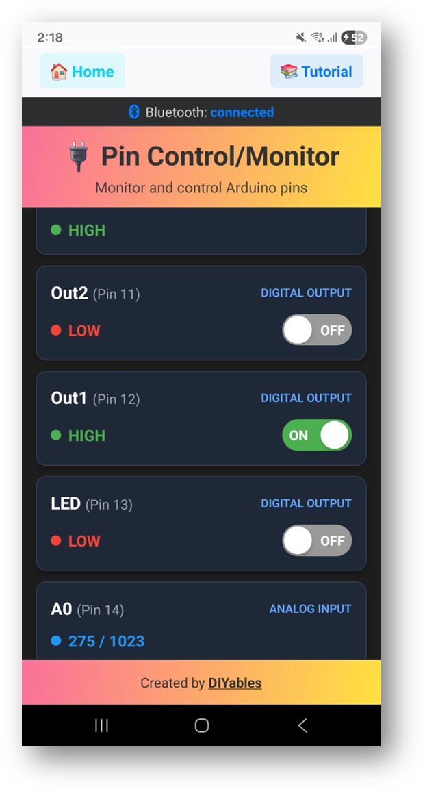
  • You will see the list of enabled pins with their names and current states
  • Tap output pins to toggle HIGH/LOW, and watch input pin values update
DIYables Bluetooth App - Digital Pins Screen

Now look back at the Serial Monitor on Arduino IDE. You will see:

COM6
Send
Bluetooth connected! Pin 13 set to HIGH Pin 13 set to LOW Digital pin 7 read: HIGH
Autoscroll Show timestamp
Clear output
9600 baud  
Newline  

Creative Customization - Adapt the Code to Your Project

Enable Pins

// Enable pins with mode and friendly name bluetoothPins.enablePin(13, BT_PIN_OUTPUT, "LED"); bluetoothPins.enablePin(12, BT_PIN_OUTPUT, "Relay"); bluetoothPins.enablePin(7, BT_PIN_INPUT, "Button"); bluetoothPins.enablePin(A0, BT_PIN_INPUT, "Sensor"); // Check enabled pin count int count = bluetoothPins.getEnabledPinCount();

Handle Pin Write/Read/Mode

bluetoothPins.onPinWrite([](int pin, int state) { digitalWrite(pin, state); Serial.print("Pin "); Serial.print(pin); Serial.println(state ? " ? HIGH" : " ? LOW"); }); bluetoothPins.onPinRead([](int pin) -> int { if (pin >= A0) { return analogRead(pin); } return digitalRead(pin); }); bluetoothPins.onPinModeChange([](int pin, int mode) { pinMode(pin, mode == BT_PIN_OUTPUT ? OUTPUT : INPUT_PULLUP); });

Push State Changes

// Notify the app when a pin state changes bluetoothPins.updatePinState(7, digitalRead(7)); bluetoothPins.updatePinState(A0, analogRead(A0));

Programming Examples

Relay Control with Button Monitor

const int RELAY_PIN = 12; const int BUTTON_PIN = 7; void setup() { pinMode(RELAY_PIN, OUTPUT); pinMode(BUTTON_PIN, INPUT_PULLUP); bluetoothPins.enablePin(RELAY_PIN, BT_PIN_OUTPUT, "Relay"); bluetoothPins.enablePin(BUTTON_PIN, BT_PIN_INPUT, "Button"); bluetoothPins.onPinWrite([](int pin, int state) { digitalWrite(pin, state); }); } void loop() { bluetoothServer.loop(); // Monitor button and push changes static int lastState = HIGH; int state = digitalRead(BUTTON_PIN); if (state != lastState) { lastState = state; bluetoothPins.updatePinState(BUTTON_PIN, state); } delay(10); }

Multi-LED Controller

const int LED_PINS[] = {8, 9, 10, 11, 12, 13}; const char* LED_NAMES[] = {"Red", "Green", "Blue", "Yellow", "White", "Built-in"}; const int NUM_LEDS = 6; void setup() { for (int i = 0; i < NUM_LEDS; i++) { pinMode(LED_PINS[i], OUTPUT); bluetoothPins.enablePin(LED_PINS[i], BT_PIN_OUTPUT, LED_NAMES[i]); } bluetoothPins.onPinWrite([](int pin, int state) { digitalWrite(pin, state); }); }

Troubleshooting

Common Issues

1. Cannot find the device in the app

  • Make sure the Arduino UNO R4 WiFi is powered on and the sketch is uploaded
  • Ensure your phone's Bluetooth is enabled
  • On Android 11 and below, also enable Location services

2. Pin toggle not working

  • Verify the pin is enabled with BT_PIN_OUTPUT mode
  • Check that onPinWrite callback is set up
  • Verify wiring connections

3. Input pins not updating

  • Ensure updatePinState() is called when pin state changes
  • Check polling frequency in the loop

4. Analog values not showing

  • Use analogRead() in the onPinRead callback for analog pins
  • Analog pins return 0-1023 values

5. Connection drops frequently

  • Move closer to the Arduino (reduce distance)
  • Ensure stable USB power supply

6. Upload fails or board not recognized

  • Install the latest Arduino UNO R4 board package via Board Manager
  • Try a different USB cable or port

Project Ideas

  • Multi-relay control panel
  • Button and switch monitor
  • LED lighting controller
  • Home automation switch panel
  • Sensor input dashboard

Next Steps

After mastering the Bluetooth Digital Pins example, try:

  1. Bluetooth Slider - For analog value control
  2. Bluetooth Monitor - For text-based status feedback
  3. Bluetooth Table - For structured pin status display
  4. Multiple Bluetooth Apps - Combining pin control with other apps

Support

For additional help:

※ OUR MESSAGES

  • As freelancers, We are AVAILABLE for HIRE. See how to outsource your project to us
  • Please feel free to share the link of this tutorial. However, Please do not use our content on any other websites. We invested a lot of effort and time to create the content, please respect our work!